Table of Contents
Advertisement
Quick Links
Advertisement
Table of Contents

Subscribe to Our Youtube Channel
Related Manuals for Power Measurement ION 8000 Series


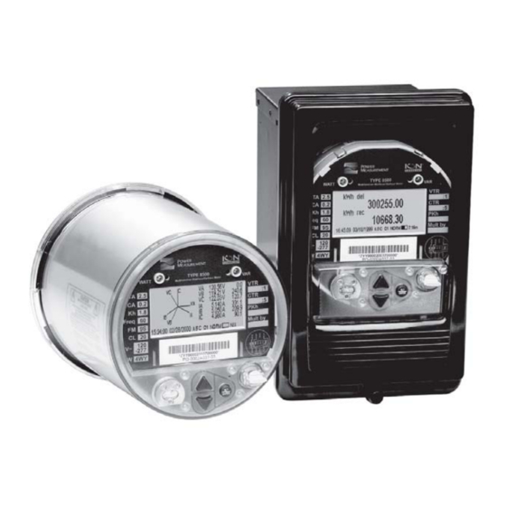
Summary of Contents for Power Measurement ION 8000 Series
- Page 3 This symbol directs the user’s attention to important installation, operating and maintenance instructions. Retrofit Considerations Retrofit and maintenance of the ION 8000 series meter should only be performed by qualified, competent personnel that have appropriate training and experience with high voltage and current devices. The meter must be installed in accordance with all Local and National Electrical Codes.
- Page 4 The Ringer Equivalence Number (REN) for the ION 8000 series optional internal modem is 0.6. Connection to the ION 8000 series internal modem should be made via an FCC Part 68 compliant telephone cord (not supplied). The ION 8000 series cannot be used on a public coin phone service or party line services.
-
Page 5: Table Of Contents
“Replacing the Display Cover (Switchboard Meter)” on page 25 “Replacing the Power Cable (Switchboard Meter)” on page 26 RMICAN Model ION 8000 series socket and switchboard meters can be Industry Canada certified for revenue metering in Canada. Different security options are available, including a factory-sealed version. - Page 6 Before You Begin Familiarize yourself with the steps in this guide and read the safety precautions presented on the “Retrofit Considerations” page. ANGER Ensure the meter has been unpowered for at least 10 minutes prior to assembly. This ensures the meter capacitors contain no residual charge. The disconnected meter retains all its configuration settings.
-
Page 7: Accessing The Socket Meter's Pc Boards
Accessing the Socket Meter’s PC Boards Ensure the meter has been unpowered for at least 10 minutes prior to disassembly. This ensures the meter capacitors contain no residual charge. The disconnected meter retains all its configuration settings. In each retrofit scenario, you must first remove the plastic cover and the shield of the socket meter to access the circuit boards. - Page 8 Access the meter’s PCBs Remove the two screws from the shield and lift the shield off the meter. Disconnect the ground cable and remove the four case side screws.
- Page 9 Remove the side case cover and expose the meter cards.
-
Page 10: Replacing The I/O Card
Replacing the I/O Card Remove the meter’s cover and shield by following the steps outlined in “Accessing the Socket Meter’s PC Boards” on page 7. Remove display board and expose the I/O card. Disconnect all wire plugs at the front end of the I/O card by lifting locking tabs with a fine point tool. -
Page 11: Replacing The Communications Card
Replacing the Communications Card Remove the meter’s cover and shield by following the steps outlined in “Accessing the Socket Meter’s PC Boards” on page 7. Remove display board by gently prying tabs back, pulling straight up on the display board. Attempting to remove the Display unit at an angle will damage its connector on the CPU. -
Page 12: Replacing The Power Supply Cards
Replacing the Power Supply Cards Remove the meter’s cover and shield by following the steps outlined in “Accessing the Socket Meter’s PC Boards” on page 7. Remove the display board and slide out the I/O card (if applicable) and the communications board, exposing the two power supply cards. Disconnect and slide the top power supply card out slightly to clear its header pins. - Page 13 Slide out the power supply pair of boards. Insert, as a pair, the new bottom power supply (connect to side socket) and the top power supply (connect to the CPU board). Re-insert the communications board, the I/O card (if applicable) and the display board.
-
Page 14: Replacing The Display
Replacing the Display Remove the meter’s cover and shield by following the steps outlined in “Accessing the Socket Meter’s PC Boards” on page 7. Remove display board by carefully prying tabs back and pulling straight up. Angling the display board will damage the connector on the CPU. Insert new display, ensuring proper orientation. -
Page 15: Replacing The Plastic Cover
Replacing the Plastic Cover Remove the meter’s cover by following the three steps outlined in “Remove the plastic cover” on page 7. Remove the shield as outlined in “Access the meter’s PCBs” on page 8. Insert new cover by aligning the rim slots and press down, twisting clockwise. -
Page 16: Accessing The Switchboard Meter's Pc Boards
Accessing the Switchboard Meter’s PC Boards Ensure the meter has been unpowered for at least 10 minutes prior to disassembly. This ensures the meter capacitors contain no residual charge. The disconnected meter retains all its configuration settings. In each retrofit scenario, you must first remove the meter from its switchboard casing to access the circuit boards. - Page 17 Slide metal brackets a & b in the direction and final position shown. Slide all teeth from the front of the switchboard into the open position.
- Page 18 Press the top of the meter down and pull out of switchboard. Remove the meter from its switchboard frame Mark the position of the six wires at the bottom of the assembly and unscrew. Terminal tabs are copper; avoid stripping.
- Page 19 Disconnect white connector. Remove the four screws holding the meter to the cage and remove cage.
- Page 20 Remove the two screws and release the bracket from the base of the meter. 10. Remove the two screws from the side of the meter and pull out side panel to expose the meter's boards.
-
Page 21: Replacing The Battery (Switchboard Meter)
Replacing the Battery (Switchboard Meter) Follow the steps outlined in “Remove the meter from its switchboard casing” on page 16 to access the meter. Disconnect battery wires and remove battery from socket. Replace battery. Return the meter into the switchgear case, reversing the steps outlined in “Remove the meter from its switchboard casing”... -
Page 22: Replacing The Case Jaws (Switchboard Meter)
Replacing the Case Jaws (Switchboard Meter) Follow the steps outlined in “Remove the meter from its switchboard casing” on page 16 to access the meter. Remove the two screws, one on each side of the case and the two screws from the back of the case. -
Page 23: Replacing The Communications Board (Switchboard Meter)
Replacing the communications board (Switchboard Meter) Follow the steps outlined in “Accessing the Switchboard Meter’s PC Boards” on page 16 to access the meter. Disconnect all wires from the front of the communications board as well as the ground wire. Slide communications board out and replace, re-connecting all wires. -
Page 24: Replacing The I/O Card (Switchboard Meter)
Replacing the I/O Card (Switchboard Meter) Follow the steps outlined in “Accessing the Switchboard Meter’s PC Boards” on page 16 to access the meter. Disconnect all wires from the front of the I/O card. Slide I/O card out and replace, re-connecting all wires. Re-assemble meter and cage following the reverse order of steps outlined in “Remove the meter from its switchboard frame”... -
Page 25: Replacing The Display Cover (Switchboard Meter)
Replacing the Display Cover (Switchboard Meter) Release the screw at the front bottom of the display cover and lift. To install new cover, align the hinge at the top back of the cover and secure with screw. -
Page 26: Replacing The Power Cable (Switchboard Meter)
Replacing the Power Cable (Switchboard Meter) Follow the steps outlined in “Remove the meter from its switchboard casing” on page 16 to access the meter. Carefully cut the zap straps holding the cables at the back of the case. Remove the four cable socket screws from the inside of the case. - Page 27 Remove the metal shield covering the wires from the back of the case. Remove the assembly of cables by pushing out the white connector through the inside of the case. Use a 1/4” socket to unlock inner tabs by simultaneously turning and pushing overtop. Replace connector ensuring the orientation shown below.
- Page 28 Re-insert the wire shield at the back of the case and secure cables with zap straps provided through the slots of the case. Return the meter into the switchgear case, reversing the steps you followed in “Accessing the Switchboard Meter’s PC Boards” on page 16. AUTION When replacing shield, ensure wires are not pinched in screw standoffs.
- Page 32 For further assistance please contact us at: Worldwide Headquarters 2195 Keating Cross Road Saanichton, BC Canada V8M 2A5 Tel: 1-250-652-7101 Fax: 1-250-652-0411 Email: support@pwrm.com www.pwrm.com © 2004 Power Measurement Printed in Canada MRP: 70000-0202-00 Revision Date: Oct 4, 2004...
Need help?
Do you have a question about the ION 8000 Series and is the answer not in the manual?
Questions and answers