Table of Contents
Advertisement
Quick Links
Advertisement
Table of Contents

Related Manuals for Associated Research HYAMP III 3140


Summary of Contents for Associated Research HYAMP III 3140
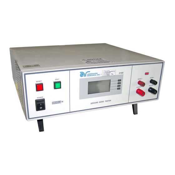
- Page 1 OPERATION AND SERVICE MANUAL HYAMP ® MODELS 3140 and 3160 GROUND BOND TESTERS SERIAL NUMBER Model © Associated Research, Inc., 2015 13860 West Laurel Drive 3140,3160 Lake Forest, Illinois 60045-4546 U.S.A. Item 38554 Ver 3.10 Printed April 27, 2016...
-
Page 3: Declaration Of Conformity
DECLARATION OF CONFORMITY Manufacturer: Associated Research, Inc. Address: 13860 W. Laurel Dr. Lake Forest, IL 60045 ® Product Name: HYAMP III Ground Bond Tester Model Number: 3140, 3160 Conforms to the following Standards: Safety: UL 61010-1:2012, UL 61010-2-030:2012 CAN/CSA-C22.2 NO. 61010-1-12 CAN/CSA-C22.2 NO. -
Page 5: Table Of Contents
TABLE OF CONTENTS 1. INTRODUCTION ....................1 1.1. Warranty Policies ..................1 1.2. Safety Symbols ....................3 1.2.1. Product Marking Symbols ..............3 1.2.2. Caution and Warning Symbols ............3 1.3. Glossary of Terms ..................3 1.4. Safety ......................5 1.4.1. - Page 6 4.3.1. Test Setup Soft Keys ................ 33 4.3.2. Test Parameters ................33 4.3.3. Default Parameters ................34 4.3.4. Setting Up a Test ................35 5. OPERATING INSTRUCTIONS ............... 36 5.1. Instrument Connections ................36 5.1.1. Test Leads ..................36 5.1.2. Adapter Box Connections (Adapter box is sold separately) ..38 5.1.3.
-
Page 7: Introduction
5-Year Program All Associated Research instruments include the opportunity to extend the standard warranty for up to a period of 5 years. Returning instruments to Associated Research for their annual calibration and inspection will extend the instrument's warranty for an additional year. - Page 8 Elimination of any connections in the earth grounding system or bypassing any safety systems will void this warranty. This warranty does not cover accessories not of Associated Research, Inc. manufacture. Parts used must be parts that are recommended by Associated Research, Inc. as an acceptable specified part. Use of non-authorized parts in the repair of this instrument will void the warranty.
-
Page 9: Safety Symbols
1.2. Safety Symbols 1.2.1. Product Marking Symbols Product will be marked with this symbol when it is necessary to refer to the operation and service manual in order to prevent injury or equipment damage. Product will be marked with this symbol when hazardous voltages may be present. - Page 10 Dielectric: An insulating material that is positioned between two conductive materials in such a way that a charge or voltage may appear across the two conductive materials. Direct Current, DC: Current that flows in one direction only. The source of direct current is said to be polarized and has one terminal that is always at a higher potential than the other.
-
Page 11: Safety
Any external cleaning failure indication. should be done with a clean, dry or slightly damp cloth. Schematics, when provided, are for reference only. Refer servicing and certification to an Associated Research, Inc. authorized service center. ASSOCIATED RESEARCH, INC. (PHONE: 1 (847) 367-4077... -
Page 12: Test Station
Service Interval Associated Research, Inc. will not be held liable for injuries suffered if the instrument is not properly maintained and safety checked annually. See section 1.1. Warranty Policies for more information. 1.4.2. Test Station Location Select an area away from the mainstream of activity where employees do not walk while performing their normal duties. -
Page 13: Test Operator
1.4.3. Test Operator This instrument generates voltages and currents that can cause harmful or fatal electric shock and must only be operated by a skilled worker trained in its use. The operator should understand the electrical fundamentals of voltage, current, and resistance. DO NOT TOUCH THE DEVICE UNDER TEST, TEST LEADS, ALLIGATOR CLIP, OR CLIP INSULATOR ONCE THE TEST HAS BEEN STARTED. - Page 14 instrument may cause heart-related problems. Please have the test operator consult a physician for recommendations.
-
Page 15: Key Features And Benefits
1.5. Key Features and Benefits: HYAMP III Provides the operator with an easy-to-use THE FIRST MANUAL interface, eliminating the need to decipher cryptic GROUND BOND abbreviations. The graphic display makes testing INSTRUMENT WITH AN safer, easier and more reliable than ever before. ENHANCED GRAPHIC LCD Limit user access so that only authorized SECURITY ACCESS... -
Page 16: Getting Started
2. GETTING STARTED Introduction This section contains information for the unpacking, inspection, preparation and storage of your Associated Research, Inc., product. 2.1. Unpacking and Inspection 2.1.1. Packaging Your instrument was shipped in a custom foam insulated container. If the shipping carton is damaged, inspect the contents for visible damage such as dents, scratches or a broken display. - Page 17 DESCRIPTION AR PART NUMBER AR PART NUMBER DESCRIPTION AR PART NUMBER AR PART NUMBER HYAMP III Instrument 3140 3160 Cable ASSY High 38489 Current with Kelvin 38429 Current with Kelvin Current Output Cable ASSY High 38490 Return with Kelvin 38457 Return with Kelvin Current Return Fuse 38503, 10 Amp, Slow Blow...
-
Page 18: Installation
3160 Carton Contents 2.2. Installation 2.2.1. Work Area Locate a suitable testing area and be sure you have read all safety instructions for the operation of the instrument and suggestions on the test area setup in section 1.4. Safety. Make sure the work area you choose has a three-prong grounded outlet capable of supplying the necessary input current to the power source. -
Page 19: Basic Connections
Do not replace the power supply cord with an improperly rated cord. For North American: A UL listed and CSA labeled power cord must be used with the instrument in the United States and Canada. The power cord must include a NEMA5-15 style male plug, SVT or SJT cord sets, and be rated for at least 125VAC, 10A, number 16 gauge (or 125VAC, 15A, number 14 gauge) wire or larger, and the length of the cord does not exceed 2 m must be used. - Page 20 This equipment is intended for indoor use only. The equipment has been evaluated according to Installation Category II and Pollution Degree 2 as specified in IEC 664. This instrument may be operated in environments with the following limits: Temperature…....41° - 104° F (5° - 40°C) Relative humidity…...
-
Page 21: Specifications And Controls
3. SPECIFICATIONS AND CONTROLS 3.1. 3140 HYAMP III Functional Specifications INPUT Voltage 115/230 VAC ± 10%, user selectable Frequency 50/60 Hz ± 5% Fuse 10 Amp, slow-blow 250 V AC TEST MODE Output Rating Current: 1.00 – 40.00 Amps AC Resolution: 0.01 Amp/step Regulation:... - Page 22 Resolution: 0.1 seconds Accuracy: ± (0.1% of reading + 0.05 seconds) GENERAL Remote Control And Signal The following input and output signals are provided Output through two 9 pin D type connectors; 1. Remote control: Test, Reset, Interlock, and Withstand Processing. 2.
-
Page 23: 3160 Specifications
3.2. 3160 HYAMP III Functional Specifications INPUT Voltage 115/230 VAC ± 10%, user selectable Frequency 50/60 Hz ± 5% Fuse 15.0 Amp, slow-blow 250 V AC TEST MODE Output Rating Current: 1.00 – 60.00 Amps AC Resolution: 0.01 Amp Regulation: ±... - Page 24 GENERAL Remote Control And The following input and output signals are provided Signal Output through two 9 pin D type connectors; 1. Remote control: Test, Reset, Interlock, and Withstand Processing. 2. Remote recall of memory program #1, #2 and #3. 3.
-
Page 25: Instrument Controls
3.3. Instrument Controls 3.3.1. Front Panel Controls for 3140 1. RESET BUTTON: Momentary contact switch used to reset the instrument. If a failure condition occurs during a test, you will need to reset the system to shut off the alarm and signal the system that you are aware of a failure condition. The reset button must be pressed before you can proceed to the next test or change any of the set-up parameters. - Page 26 7. SENSE- JACK: Connector used to attach the Return test lead or test fixture to the instrument. This connector provides a negative Kelvin voltage sensing for the instrument. 8. POWER SWITCH: Rocker style power switch with international ON ( | ) and OFF (0) markings.
-
Page 27: Rear Panel Controls For 3140
5. CURRENT OUTPUT JACK: Connector used to attach the Current test lead, adapter box, or test fixture to the instrument. 6. SENSE+ JACK: Connector used to attach the Current test lead or test fixture to the instrument. This connector provides a positive Kelvin voltage sensing for the instrument. -
Page 28: Rear Panel Controls For 3160
3. INPUT POWER SWITCH: Line voltage selection is set by the position of the switch. In the left position it is set for 115 volt operation, in the right position it is set for 230 volt operation. 4. CHASSIS GROUND (EARTH) TERMINAL: This terminal should be connected to a good earth ground before operation. - Page 29 4. REMOTE SIGNAL INPUT: 9-Pin D subminiature male connector for remote control of TEST, RESET, and INTERLOCK functions, as well as remote program memory selection and withstand processing input. 5. REMOTE SIGNAL OUTPUT: 9-Pin D subminiature female connector for monitoring PASS, FAIL, PROCESSING, and RESET output relay signals. 6.
-
Page 30: Programming Instructions
4. PROGRAMMING INSTRUCTIONS 4.1. Power Up The HYAMP III automatically defaults to the Perform Tests screen upon power up. The Perform Tests screen will appear as follows: The Perform Tests screen is the main operational screen of instrument. From this screen, all test parameters are monitored while the test is being performed. -
Page 31: Results, Tests And System Selections
The Main Menu will now be displayed. From the Main Menu screen, three software controls may be accessed: Menu, Memory and Step. Pressing the “Exit” soft key at any time will return you to the Perform Tests screen. Menu Pressing the “Menu” soft key from the Main Menu will display the Results, Test and System selections. -
Page 32: System Setup
Results Pressing the “Results” soft key from this menu will allow you to review the test results of the last test performed. An example of a Results screen is shown below. Test Pressing the “Test” soft key from this menu will allow you to access the Parameter Review screen. -
Page 33: System Setup Soft Keys
You can control your I/O. If you attempt to start a test from the Associated Research, Inc. TEST button on the front panel when the instrument using basic PLC PLC Remote function is turned ON, a pop- inputs and outputs. - Page 34 completed. To continue the test sequence, press the TEST button to execute the next connected test step. Each time the TEST button is pressed the next connected test step will execute. If you press the RESET button before completing all connected test steps, it will return you to the original starting test step.
- Page 35 When P/F is selected, it is not possible to see the test results directly at the end of the test. In order to review the test results refer to section 4.2.3. Reviewing Test Results. When Last is selected, the results of the last test step performed will be displayed on the Perform Tests screen.
- Page 36 The Hipot Start parameter is only used when connecting the HYAMP III with an Associated Research Hipot tester. If G→W is selected, the Hipot test will run after the HYAMP III has completed its test. If G + W is selected, the Hipot test will run at the same time as the HYAMP III.
- Page 37 Within the Set Date parameter are four fields, date format (mdy / dmy), month, day, and year. Use the “>” soft key to select the field within the date you want to edit. Use the “+” soft key to change the numeric value. Once you change the value it is automatically stored.
-
Page 38: Default System Parameters
4.2.3. Default System Parameters Setup System PLC Remote Single Step Alarm Contrast Results Last Lock Mem Lock Hipot Start G→W Date Format mdy (month, day, year) Cal Alert Alert Date Cal Date + 11 months 4.2.4. Memory, Step, and Default System Parameter Restore Restoring the instrument’s System parameters will overwrite all memories and steps with ACW default parameters! Press the two bottom soft keys and power the instrument at the same time, then press... -
Page 39: Test Setup Soft Keys
4.3.1. Test Setup Soft Keys Directional soft keys ∧,∨, > The “∧,∨, > ” soft keys are used to scroll the cursor to the different system parameters. +/- keys The “+” and “-“ soft keys are used to increase or decrease numerical values or toggle settings ON and OFF. -
Page 40: Default Parameters
Offset The Offset function may be used to compensate for test lead and test fixture resistance during the test. Using the up and down arrow keys, scroll the cursor to the Offset parameter and press the “Edit” soft key. You may now manually or automatically set an Offset value. -
Page 41: Setting Up A Test
4.3.4. Setting Up a Test From the Test Parameters Review screen scroll the cursor using the “∧” and “∨” soft keys to the Current parameter. Press the “Edit” soft key. Increase or decrease the Current parameter using the up and down arrow keys. Press the “Enter” soft key to accept the parameters or press the “Esc”... -
Page 42: Operating Instructions
5. OPERATING INSTRUCTIONS 5.1. Instrument Connections 5.1.1. Test Leads The test leads provided are designed specifically for use with this instrument. The red High Current lead will mate with the red Current jack. The black Return lead will mate with the black Return jack. The test lead ratings are as follows: 3140 TEST LEAD RATINGS 3160 TEST LEAD RATINGS... - Page 43 Connect the Return lead (38490 Heavy gauge wire, black markers) to the Return receptacle on the 3140 HYAMP III, then connect the Kelvin lead (smaller gauge wire captured in the same sleeve) to the SENSE- receptacle. Next, connect the other end of the lead to chassis ground.
-
Page 44: Adapter Box Connections (Adapter Box Is Sold Separately)
5.1.2. Adapter Box Connections (Optional, for use with 3140 only) The adapter box provides an easy way to connect a DUT to a 3140 HYAMP III that is terminated in a two or three-prong line cord. The following diagram shows how to connect the adapter box to the HYAMP III and to the device under test. -
Page 45: Performing A Test
5.2. Performing a Test 1. From the Main Menu, select the memory and step you wish to perform then press the “Exit” soft key to return to the Perform Tests screen. 2. Attach the appropriate load or DUT to the instrument. Refer to section 5.1. Instrument Connections for instrument connections. -
Page 46: Error Messages
5.5. Error Messages While performing tests a number of messages will be displayed to indicate the test state or test results. These messages are displayed in the status area of the screen located on the first line at the top of the LCD. These messages are also used on other screens where test results are displayed. -
Page 47: Connection Of Remote I/O
6. CONNECTION OF REMOTE I/O Two 9 pin D-type connectors mounted on the rear panel provide REMOTE-INPUT- OUTPUT control and information. These connectors mate with a standard 9 pin D- type subminiature connector provided by the user. The output mates to a male (plug) connector while the input mates to a female (receptacle) connector. -
Page 48: Signal Inputs Of Remote I/O And Memory Access
The Hipot Start parameters main purpose is to control the sequential timing between HYAMP III and a connected Associated Research Hipot. The parameter controls if the Hipot will run after the HYAMP III has completed its test, G→W, or if the Hipot will run at the same time as the HYAMP III, G + W. - Page 49 The HYAMP III remote connector enables remote operation of the TEST, RESET, and REMOTE INTERLOCK functions, and allows the operator to select Memory Location 1, 2, and 3. When the PLC Remote mode is on, the HYAMP III will respond to simple switch or relay contacts closures.
- Page 50 Remote Interlock HYAMP III is equipped with a Remote Interlock feature. Remote Interlock utilizes a set of closed contacts to enable the instrument’s output. If the Remote Interlock contacts are open the output of the instrument will be disabled. Remote Interlock could also be referred to as a remote system lockout, utilizing “fail when open”...
- Page 51 If the Hipot start signal is set to G+W then a small “W-T” indicator will appear in the upper right of the display. PLC Remote Pop-up message If you attempt to start a test from the front panel TEST button and the PLC remote function is turned “ON”, a pop-up message will be displayed.
-
Page 52: Hyamp Iii Connected To Hypot Iii
6.3. HYAMP III Connected to Hypot III 6.3.1. 3140 HYAMP III Connected to Hypot III The following illustration and should be used to configure the 3140 HYAMP III for integrated operation with HYPOT III: Both front and rear connections may be used to connect the adapter box and interconnect. -
Page 53: 3160 Hyamp Iii Connected To Hypot Iii
When Hypot III is connected to HYAMP III, the Hypot III should have PLC remote turned on. In this configuration, you will only be able to start and reset the HYAMP III from the HYAMP III. It is possible to reset or abort the Hipot from both instruments. 3160 HYAMP III Connected to HYPOT III The following illustration and should be used to configure the 3160 HYAMP III for integrated operation with HYPOT III:... - Page 55 The Hipot Start parameter is only used when connecting the HYAMP III with an Associated Research Hypot III. The parameter determines if the Hipot will run after the HYAMP III has completed its test, G→W, or if the Hipot will run at the same time as the HYAMP III, G + W.
-
Page 56: Options
7. OPTIONS Introduction This section contains a list and descriptions of available factory installed options at the time of this printing. The list of options contains an option code number that can be referenced on the data plate on the rear panel of the unit. Option Label On the rear panel of the instrument, you will find a label that contains the option code. -
Page 57: Instrument Verification
8. INSTRUMENT VERIFICATION Verification is the process by which an instrument’s failure detectors are proven to be functioning properly by performing basic tests in open and short circuit conditions. Verifying the failure detection circuitry of the electrical safety tester is required by safety agencies such as CSA, UL, and TÜV. - Page 58 Ground Bond Verification From the Verification screen, press the TEST button to begin the verification process. At the end of the Verification process, a message will appear indicating the outcome of the process. If the instrument passes the Verification (test failure, indicating the fail detectors are working properly) the RESET button will illuminate, the alarm will sound and the following message will appear: If the instrument fails the Verification (test pass, indicating the fail detectors are not...
-
Page 59: Calibration Procedure
Associated Research, Inc. offers a standard one-year manufacturer’s warranty. This warranty can be extended an additional four years provided that the instrument is returned each year to Associated Research, Inc. for its annual recertification. In order to be eligible for the extended warranty instruments must be returned to Associated Research, Inc. -
Page 60: Calibration Of Parameters
9.2.1. Calibration of Parameters From the Calibration screen, use the “∨ “ soft key to scroll the cursor to the parameter you wish to calibrate. Once the cursor is pointing to the parameter you wish to calibrate, press the “Select” soft key. A calibration prompt screen will now appear. The following is a list of the calibration parameters and an example of the prompt screen with the details that will be displayed for each parameter (screen shown at left). -
Page 61: Calibration Of Ground Bond Ac Current For 3160
9.2.3. Calibration of Ground Bond AC Current for 3160 9.2.4. Calibration of Ground Bond AC Voltage for 3140 ____________________________________________________________________________... -
Page 62: Calibration Of Ground Bond Ac Voltage For 3160
9.2.5. Calibration of Ground Bond AC Voltage for 3160 Remove the red high current lead from its binding post and place it on to the Sense+ binding post. - Page 63 ____________________________________________________________________________...
-
Page 64: Replacement Parts List
10. REPLACEMENT PARTS LIST Rev. C 03/21/2014 ECO 5696 3140 PART REFERENCE QTY. DESCRIPTION NUMBER DESIGNATOR Supplied Accessories 38503 Fuse, 10 Amp slow-blow 250VAC Cable HC Current 2Wire MC 40A 38489 38490 Cable HC Return 2Wire MC 40A 38075 Interlock Connector 38482 Adapter Box, 3140 Only (optional) 33189... - Page 65 Rev B, 03/21/2014 ECO 5696 3160 PART REFERENCE DESCRIPTION PART REFERENCE DESCRIPTION NUMBE DESIGNATOR NUMBE DESIGNATOR Supplied Accessories 38430 Fuse, 15 Amp, slow-blow 250VAC Cable ASSY High Current Output 38429 38457 Cable ASSY High Current Return 38075 Interlock Connector 38071 Cable Input Cordset USA Panel Components 38443...
- Page 67 Index Adapter Box ................... 20, 21, 22, 40, 48, 60 Arc ........................... 3, 37 Benefits .......................... 9 Breakdown ......................... 3, 4 Calibration ....................12, 31, 32, 55 Calibration Alert Alert Date ......................31, 32 Cal Alert ....................27, 31, 32, 34 Cal Date .......................
- Page 68 Test Parameters ................9, 17, 19, 25, 27, 35 PLC ......................27, 28, 34, 45 Power ........................4, 6, 13 Power Factor ......................... 4 Programming ....................... 25 Rear Panel Controls ..................13, 22, 23 Receptacle ......................22, 43 Regulation ......................16, 18 Remote ....
Need help?
Do you have a question about the HYAMP III 3140 and is the answer not in the manual?
Questions and answers