Table of Contents
Advertisement
©2002 Lennox Industries Inc.
Dallas, Texas
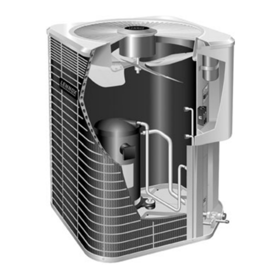
HSXA12 Outdoor Unit
HSXA12 outdoor units use R410A which is an ozone
friendly HFC refrigerant. This unit must be installed with a
matching indoor coil and line set as outlined in the Lennox
Engineering Handbook. HSXA12 outdoor units are de-
signed for use in expansion valve (TXV) and fixed orifice
systems. Refer to the Lennox Engineering Handbook for
expansion valve kits which must be ordered separately. A
filter dryer approved for use with R410A has been shipped
with the unit. This component must be installed prior to op-
erating the unit. Failure to install the provided filter dryer
will void the warranty.
Shipping and Packing List
1 − Assembled HSXA12 outdoor unit
1 − Liquid line filter drier (approved for use with R410A
systems)
1 − Fixed orifice refrigerant metering device
Check equipment for shipping damage. If you find any
damage, immediately contact the last carrier.
WARNING
Improper installation, adjustment, alteration, service
or maintenance can cause property damage, person-
al injury or loss of life. Installation and service must
be performed by a qualified installer or service
agency.
IMPORTANT
This unit must be matched with an indoor coil as
specified in Lennox' Engineering Handbook. Coils
previously charged with R22 must be flushed.
04/04
*2P0404*
INSTALLATION
INSTRUCTIONS
HSXA12 Series Units
CONDENSING UNITS
504,540M
04/04
Supersedes 12/03
Table of Contents
. . . . . . . . . . . . . . . . . . . . . . . . . . . . . . . .
. . . . . . . . . . . . . . . . . . . . . . . . . . . . . . . . .
. . . . . . . . . . . . . . . . . . . . . . . . . . . . . . . . . . . . . .
. . . . . . . . . . . . . . . . . . . . . . . . . . . . . . . .
. . . . . . . . . . . . . . . . . . . . . . . . . . . . . . . . . .
. . . . . . . . . . . . . . . . . . . . . . . . . . . . . . . . . . .
. . . . . . . . . . . . . . . . . . . . . . . . . . . . . . . . . . . . . .
. . . . . . . . . . . . . . . . . . . . . . . . . . . . . . . . . . . . .
. . . . . . . . . . . . . . . . . . . . . . . . . . . . . . . . . .
RETAIN THESE INSTRUCTIONS
FOR FUTURE REFERENCE
General Information
These instructions are intended as a general guide and do
not supersede national or local codes in any way. Consult
authorities having jurisdiction before installation.
This product and/or the indoor unit it is matched with
may contain fiberglass wool.
Disturbing the insulation during installation, mainte-
nance, or repair will expose you to fiberglass wool
dust. Breathing this may cause lung cancer. (Fiber-
glass wool is known to the State of California to
cause cancer.)
Fiberglass wool may also cause respiratory, skin,
and eye irritation.
To reduce exposure to this substance or for further
information, consult material safety data sheets
available from address shown below, or contact your
supervisor.
Lennox Industries Inc.
P.O. Box 799900
Dallas, TX 75379−9900
Page 1
. . . . . . . . . . . . . . . . . . . . . . . . . . .
. . . . . . . . . . . . . . . . . . . . . . .
. . . . . . . . . . . . . . . . . . . . . . . . . . . . .
. . . . . . . . . . . . . . . . . . . . . . . . . . . . . .
. . . . . . . . . . .
. . . . . . . . . . . . . . . . . . . .
. . . . . . . . . . . . . . . . . . . . . . . . . . . .
. . . . . . . . . . . . . . . . . . . . . . . . . . . . .
. . . . . . . . . . . . . . . . . . . . . . . . . .
. . . . . . . . . . . . . . . . . . . . . . . . .
WARNING
504,540M
*P504540M*
Litho U.S.A.
1
1
1
2
3
3
5
5
11
11
12
13
13
14
14
18
18
18
19
Advertisement
Table of Contents

Related Manuals for Lennox HSXA12-018


Summary of Contents for Lennox HSXA12-018
-
Page 1: Table Of Contents
........matching indoor coil and line set as outlined in the Lennox Charging . -
Page 2: Unit Dimensions
CONNECTION ELECTRICAL INLETS 2-3/4 (70) 2 (51) OPTIONAL UNIT Side View Side View (19) STAND-OFF KIT (4) (Field Installed) Model No. 24-1/4 24-1/4 HSXA12-018 HSXA12-018 HSXA12-024 HSXA12-030 32-1/4 24-1/4 HSXA12-036 HSXA12-036 HSXA12-042 HSXA12-048 28−1/4 28−1/4 HSXA12 060 HSXA12-060 Page 2... -
Page 3: Setting The Unit
Roof Mounting Setting the Unit Install unit at a minimum of 4 inches above the surface of the roof. Care must be taken to ensure weight of unit is CAUTION properly distributed over roof joists and rafters. Either red- wood or steel supports are recommended. In order to avoid injury, take proper precaution when lifting heavy objects. - Page 4 Thermostat Designations Thermostat Indoor Unit NOTE − see unit wiring diagram for power supply connections. power Outdoor Unit heat Y1 Outdoor Unit cooling indoor blower C Outdoor Unit common NOTE − If the indoor unit is not equipped with blower relay. It must be field−provided and installed (P−8−3251 or equivalent). Figure 3 Typical Field Wiring Diagram *May be optional...
-
Page 5: Refrigerant Piping
(sweat connections) to the indoor coil line set isolation must be observed. (flare or sweat connections). Use Lennox L15 (sweat, non- flare) series line sets as shown in table 1 or use field-fabri- Following are some points to consider when placing and cated refrigerant lines. - Page 6 Refrigerant Line Sets How To Install Vertical Runs (new construction shown) NOTE - Similar installation practices should be used if line set is to be installed on exterior of outside wall. IMPORTANT - Refrigerant Outside Wall Vapor Line Liquid Line lines must not contact wall.
- Page 7 Refrigerant Line Sets: Installing Horizontal Runs To hang line set from joist or rafter, use either metal strapping material Wire Tie or anchored heavy nylon wire ties. (around vapor line only) 8 feet Floor Joist or Roof Rafter Tape or Wire Tie 8 feet Strapping Material (around vapor line only) Metal Sleeve...
- Page 8 Refrigerant Line Sets: Transition From Vertical To Horizontal Automotive Anchored Heavy Muffler-Type Nylon Wire Tie Hanger Wall Wall Stud Stud Strap Liquid Line Strap Liquid Line To Vapor Line To Vapor Line Liquid Line Vapor Line Metal Vapor Line Wrapped in Metal Sleeve Liquid Line...
- Page 9 Take care to empty all existing traps. Polyol silver alloy for copper−to−brass or copper−to−steel braz- ester (POE) oils are used in Lennox units charged ing) which are rated for use with R410A refrigerant. with R410A refrigerant. Residual mineral oil can act Wrap a wet cloth around the valve body and the copper as an insulator, preventing proper heat transfer.
- Page 10 clean recovery cylinder and the recovery machine 2 − Remove the existing outdoor unit. Set the new R410A unit and follow the brazing connection procedure according to the instructions provided with the recov- which begins on the previous page to make line set ery machine.
-
Page 11: Refrigerant Metering Device
Expansion valves equipped with Chatleff type fittings are lines and indoor coil before removing the recovery ma- available from Lennox. Refer to the Engineering Handbook chine, gauges and R22 refrigerant drum. Reinstall for expansion valves for use with specific match−ups. -
Page 12: Service Valves
Service Valves Service Valve (Valve Closed) The liquid line and vapor line service valves (figures 11 and stem cap 12) and gauge ports are used for leak testing, evacuating, service charging and checking charge. See table 3 for torque re- port quirements. -
Page 13: Leak Testing
2 − With both manifold valves closed, connect the cylinder Ball Valve (Valve Open) of R410A refrigerant. Open the valve on the R410A cyl- Use Adjustable Wrench inder (vapor only). To open: rotate Stem Counter-clockwise 90°. To close: rotate Stem Clockwise 90°. 3 −... -
Page 14: Start−Up
3 − Connect the vacuum pump (with vacuum gauge) to the Start−Up center port of the manifold gauge set. 4 − Open both manifold valves and start the vacuum pump. IMPORTANT 5 − Evacuate the line set and indoor unit to an absolute pressure of 23,000 microns (29.01 inches of mercu- If unit is equipped with a crankcase heater, it should ry). - Page 15 The compressor is charged with sufficient polyol ester 4 − When the heating demand has been satisfied, switch oil for line set lengths up to 50 feet (15.2 m). If oil must the thermostat to cooling mode with a set point of 68_F be added to the compressor in the field, Copeland has (20_C).
- Page 16 Table 5 R410A Temperature/Pressure Chart Temperature Pressure Temperature Pressure Temperature Pressure Temperature Pressure °F Psig °F Psig °F Psig °F Psig 100.8 178.5 290.8 445.9 102.9 181.6 295.1 451.8 105.0 184.3 299.4 457.6 107.1 187.7 303.8 463.5 109.2 190.9 308.2 469.5 111.4 194.1...
- Page 17 Approach Method and frigerant from the system to increase the approach temperature. Normal Operating Pressures Be aware of the R410A refrigerant cylinder. It will be TXV Systems – Outdoor Temp. > 65_F (18_C) rose−colored. Refrigerant should be added through the The following procedure is intended as a general guide and vapor valve in the liquid state.
-
Page 18: System Operation
Failure to install the filter drier will void 5 − Check for correct voltage at unit (blower operating). the warranty. A replacement filter drier is available as 6 − Check amp−draw on blower motor from Lennox. Unit nameplate_________ Actual ____________. Maintenance Optional Accessories Refer to the Engineering Handbook for optional accesso- ries that may apply to this unit. -
Page 19: Hsxa12 Check Points
HSXA12 Check Points Start−up and Performance Check List Job Name Date Job No. Job Location City State Installer City State Unit Model No. Serial No. Service Technician Nameplate Voltage Compressor Outdoor Fan Rated Load Ampacity Maximum Fuse or Circuit Breaker Electrical Connections Tight? Indoor Filter Clean? Supply Voltage (Unit Off)
Need help?
Do you have a question about the HSXA12-018 and is the answer not in the manual?
Questions and answers