Table of Contents
Advertisement
SERVICE
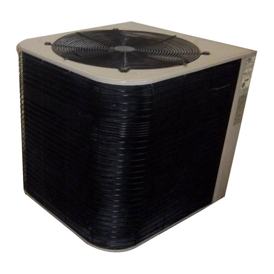
The HS26 is a high efficiency residential split−system con
densing unit which features a scroll compressor. Early
model HS26 units (−261,−311,−411, and −461) are available
in sizes ranging from 2 through 3−1/2 tons. Late model
HS26 units (−018, −024, −030, −036, −042, −048 and −060)
are available in sizes ranging from 1−1/2 through 5 tons.
The series is designed for use with an expansion valve in
the indoor unit.This manual is divided into sections which
discuss the major components, refrigerant system, charg
ing procedure, maintenance and operation sequence. In
formation in this manual covers both early and late model
HS26 units.
All specifications in this manual are subject to change.
Model No.
Face area (sq.ft.)
outer / inner
Outdoor
Tube diameter (in.)
Coil
No. of Rows
Fins per inch
Diameter (in.)
No. of Blades
Condenser
Motor hp
Fan
Cfm
RPM
Watts
HCFC−22 (charge furnished)
Liquid line connection
Suction line connection
*Refrigerant charge sufficient for 25 ft. (7.6 m) length of refrigerant lines.
Model No.
Line voltage data − 60hz./1 phase
Rated load amps
Compressor
Power factor
Locked rotor amps
Full load amps
Condenser
Fan Motor
Locked rotor amps
Max fuse or c.b. size (amps)
*Minimum circuit ampacity
*Refer to National Electrical Code Manual to determine wire, fuse and disconnect size requirements.
NOTE − Extremes of operating range are plus 10% and minus 5% of line voltage
UNIT
INFORMATION
Corp. 9622−L12
Revised 04−2002
HS26 SERIES UNITS
Late Model
HS26 shown
SPECIFICATIONS (Early Model)
HS26−261
HS26−311
11.8/5.4
15.9/5.5
3/8
3/8
1.36
1.36
20
20
24
24
3
3
1/6
1/6
3150
3150
820
820
210
210
7lbs. 11oz.
8lbs. 1oz.
3/8
3/8
3/4
3/4
ELECTRICAL DATA (Early Model)
HS26−261
HS26−311
208/230V
208/230V
11.6
13.5
.96
.96
62.5
76.0
1.1
1.1
2.0
2.0
25
30
15.6
18.0
Page 1
HS26
EARLY/LATE
MODEL SERIES
Litho U.S.A.
HS26−411
HS26−461
15.9/15.3
21.6/20.8
3/8
3/8
2.0
2.0
20
20
24
24
3
3
1/6
1/6
3000
3230
820
820
230
205
9lbs. 0oz.
11lbs. 3oz.
3/8
3/8
3/4
1 1/8
HS26−411
HS26−461
208/230V
208/230V
18.0
20
.96
.97
90.5
107
1.1
1.1
2.0
2.0
40
45
23.6
26.1
1996 Lennox Industries Inc.
Advertisement
Table of Contents

Related Manuals for Lennox HS26 Series


Summary of Contents for Lennox HS26 Series
- Page 1 Corp. 9622−L12 MODEL SERIES Revised 04−2002 Litho U.S.A. HS26 SERIES UNITS The HS26 is a high efficiency residential split−system con densing unit which features a scroll compressor. Early model HS26 units (−261,−311,−411, and −461) are available in sizes ranging from 2 through 3−1/2 tons. Late model HS26 units (−018, −024, −030, −036, −042, −048 and −060)
- Page 2 SPECIFICATIONS (Late Model) Model No. HS26 018 HS26 024 HS26 030 HS26 036 HS26 042 HS26 048 HS26 060 Outer coil 11.9 (1.11) 11.9 (1.11) 16.0 (1.59) 16.0 (1.59) 16.0 (1.59) 18.2 (1.69) 21.6 (2.01) Net face area Net face area sq.
- Page 3 All major components (indoor blower and coil) must be top of the compressor (figure1). The discharge pressure matched according to Lennox recommendations for the forcing down on the top scroll helps seal off the upper and compressor to be covered under warranty. Refer to the lower edges (tips) of the scrolls (figure 3 ).
- Page 4 HOW A SCROLL WORKS MOVEMENT OF ORBIT SUCTION SUCTION INTERMEDIATE PRESSURE CRESCENT SHAPED GAS POCKET ORBITING SCROLL SUCTION POCKET FLANKS SEALED BY STATIONARY SCROLL CENTRIFUGAL FORCE SUCTION SUCTION HIGH DISCHARGE PRESSURE POCKET FIGURE4 III−UNIT COMPONENTS CAUTION A−Transformer The contactor coil, time delay and temperature sensor Some HS26 units use single−pole contactors.
- Page 5 D−TOC Timed Off Control (Early and Late Models) Some early model HS26 units are equipped with a Lennox− built TD1−1 time delay located in the control box (figure 5). Some early and all late model HS26 units are equipped with The time delay is electrically connected between thermostat a TOC, timed off control.The TOC is located in the control...
- Page 6 HIGH PRESSURE SWITCH FIGURE 6 E−Compressor Table 1 (Early Models) Tables1 and 2 show the specifications for compressors HS 26 Phase Oil fl.oz. Unit used in HS26 series units. −261 208/230 62.5 11.6 F−Compressor High Temperature Limit −311 208/230 76.0 13.5 (Early Models) −411...
- Page 7 PRONG inside of the thermostat tube. Thermostat tube should be clean and free of debris. 4 Using Lennox kit 93G8601, dip end of thermostat into plastic bottle labeled Silicone Thermal Grease G.E. #G641" and coat end of thermostat. Care THERMAL...
- Page 8 A−Plumbing 54B64 or 12P95) Field refrigerant piping consists of liquid and suction lines from the outdoor unit (sweat connections). Use Lennox STEM CAP L10 or L15 series line sets as shown in table 6 or 7 for field− fabricated refrigerant lines. Refer to the piping section of IMPORTANT the Lennox Service Unit Information Manual (SUI−803−L9)
- Page 9 A full service non backseating suction line service valve is vice port cap is supplied to seal off the port. used on all early HS26 series units (except 461). Different manufacturers of valves may be used. All suction line service The liquid line service valve is a front and back seating valves function the same way, differences are in construction.
- Page 10 C−Service Valves (Late Models) DANGER The liquid line and suction line service valves and gauge Do not attempt to backseat this valve. Attempts to ports are accessible by removing the compressor access backseat this valve will cause snap ring to explode cover.
- Page 11 To Open Liquid or Suction Line Service Valve: V−CHARGING 1− Remove stem cap with an adjustable wrench. The unit is factory−charged with the amount of R 22 refrig erant indicated on the unit rating plate. This charge is 2− Using service wrench and 5/16" hex head extension based on a matching indoor coil and outdoor coil with a 25 back the stem out counterclockwise until the valve stem foot (7.6m) line set.
- Page 12 1− Attach gauge manifold and connect vacuum pump 5− Close nitrogen drum valve, disconnect drum from (with vacuum gauge) to center port of gauge man manifold center port and release nitrogen pressure ifold. With both gauge manifold service valves open, from system.
- Page 13 TABLE 10 (Late Models) NORMAL OPERATING PRESSURES HS26−018 HS26−024 HS26−030 HS26−036 HS26−042 HS26−048 HS26−060 OUTDOOR Liq.+ Suct.+ Liq.+ Suct.+ Liq.+ Suct.+ Liq.+ Suct.+ Liq.+ Suct.+ Liq.+ Suct.+ Liq.+ Suct.+ TEMP. (_F) 10 psig 5 psig 10 psig 5 psig 10 psig 5 psig 10 psig 5 psig...
- Page 14 VI−MAINTENANCE B−Indoor Coil 1− Clean coil if necessary. WARNING 2− Check connecting lines and coil for oil leaks. Electric shock hazard. Can cause injury 3−Check condensate line and clean if necessary. or death. Before attempting to perform C−Indoor Unit any service or maintenance, turn the electrical power to unit OFF at discon 1−...
- Page 15 VII−DIAGRAMS / OPERATING SEQUENCE A−Unit Diagram HS26−261/461−1P (Early Models) UNIT DIAGRAM Operation Sequence 1− WARNING−Early HS26 units use single− pole contactors. Capacitor terminal COM," orange condenser fan wire and red R" compressor wire are all con nected to L2 at all times. Remove all power at disconnect before servicing.
- Page 16 B−Unit Diagram HS26−018/060−2P (Late Models) Operation Sequence 1− Cooling demand energizes thermostat terminal Y. Voltage from terminal Y passes through low pressure switch and the timed off control (TOC), which energizes K1 compressor contactor coil (provided 5 minute delay is satisfied). 2−...
- Page 17 C−Unit Diagram HS26−018/060−3 & 4−P (Late Models) Operation Sequence 1− Cooling demand energizes thermostat terminal Y. Voltage from terminal Y passes through low pressure switch and the timed off control (TOC), which energizes K1 compressor contactor coil (provided 5 minute delay is satisfied).
- Page 18 C−Unit Diagram HS26−036/060−1Y, −048/−060−1G Three−phase (Late Models) Operation Sequence 1− Cooling demand energizes thermostat terminal Y. Voltage from terminal Y passes through low pressure switch and timed off control (T.O.C.), which energizes K1 compressor contactor coil (provided 5 minute delay is satisfied.) 2−...
Need help?
Do you have a question about the HS26 Series and is the answer not in the manual?
Questions and answers
How to find the age of my air conditioner unit. Thank you. Model HS26-411-1P, Serial 5894E70479.