Table of Contents
Advertisement
SERVICE
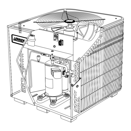
The HS25 is a high efficiency residential split–system
condensing unit which features a scroll compressor. It
operates much like a standard condensing unit, but the
HS25's scroll compressor is unique in the way that it
compresses refrigerant. Several models are available in
sizes ranging from 1–1/2 through 5 tons. The series is de-
signed for use with an expansion valve in the indoor unit.
This manual is divided into sections which discuss the
major components, refrigerant system, charging pro-
cedure, maintenance and operation sequence.
All specifications in this manual are subject to change.
SCROLL COMPRESSOR
DISCHARGE
SUCTION
UNIT
INFORMATION
Corp. 9327-L3
HS25 SERIES UNITS
I–APPLICATION
All major components (indoor blower/coil) must be
matched according to Lennox recommendations for
the compressor to be covered under warranty. Refer to
the Engineering Handbook for approved system
matchups. A misapplied system will cause erratic op-
eration and can result in early compressor failure.
II–SCROLL COMPRESSOR
The scroll compressor design is simple, efficient and
requires few moving parts. A cutaway diagram of the
scroll compressor is shown on the cover. The scrolls
are located in the top of the compressor can and the
motor is located just below. The oil level is immediate-
ly below the motor.
The scroll is a simple compression concept centered
around the unique spiral shape of the scroll and its in-
herent properties. Figure 1 shows the basic scroll form.
Two identical scrolls are mated together forming con-
centric spiral shapes (figure 2). One scroll remains sta-
tionary, while the other is allowed to orbit (figure 3).
Note that the orbiting scroll does not rotate or turn but
merely orbits the stationary scroll.
Page 1
HS25
Litho U.S.A.
Î Î Î Î
1993 Lennox Industries Inc.
Advertisement
Table of Contents

Related Manuals for Lennox HS25–211


Summary of Contents for Lennox HS25–211
- Page 1 SCROLL COMPRESSOR DISCHARGE I–APPLICATION All major components (indoor blower/coil) must be matched according to Lennox recommendations for the compressor to be covered under warranty. Refer to the Engineering Handbook for approved system SUCTION matchups. A misapplied system will cause erratic op- eration and can result in early compressor failure.
- Page 2 SPECIFICATIONS HS25–211 Model No. HS25–261 HS25–311 HS25–411 Face area (sq.ft.) - - -/11.8 5.4/11.8 5.5/15.9 5.5/15.9 inner / outer Outdoor Tube diameter (in.) Coil 1.48 1.36 1.36 No. of Rows Fins per inch Diameter (in.) No. of Blades Motor hp Condenser 2600 2450...
- Page 3 If the compressor is replaced, conventional Lennox cleanup practices must be used. Due to its efficiency, the scroll compressor is capable of drawing a much deeper vacuum than reciprocating ORBITING SCROLL compressors.
- Page 4 III–UNIT COMPONENTS C–TD1–1 Time Delay A–Transformer Each HS25 is equipped with a Lennox built TD1–1 time delay located in the control box (figure 4). The time The contactor coil, time delay and temperature sen- delay is electrically connected between thermostat ter- sor are all energized by 24VAC supplied by the indoor minal Y and the compressor contactor.
- Page 5 Thermostat tube should be clean and free of debris. 4- Using Lennox kit 93G8601, dip end of thermostat into plastic bottle la- beled “Silicone Thermal Grease G.E. #G641” and coat end of thermo- THERMAL GREASE stat.
- Page 6 Field refrigerant piping consists of liquid and suction FIGURE 7 lines from the outdoor unit (sweat connections). Use Lennox L10 series line sets as shown in table 3 or field 1 – Liquid Line Service Valve fabricated refrigerant lines. Refer to the piping section...
- Page 7 To Access Service Port: SUCTION LINE SERVICE VALVE (VALVE OPEN) 1– Remove the stem cap. Use a service wrench INSERT HEX WRENCH SNAP RING HERE (PART #49A71 AND (part #18P66, 54B64 or 12P95) to make sure the ser- KNIFE EDGE SERVICE WRENCH) SEAL vice valve is backseated.
- Page 8 *If line set is greater than 20 ft. (6.09m) add this amount. If line set CAUTION is less than 20 feet (6.09m) subtract this amount Units are designed for line sets up to 50ft. Consult Lennox Danger of Equipment Damage. Avoid deep vacu- Refrigerant Piping Manual for line sets over 50ft.
- Page 9 2– Adjust blower cooling speed. Check static pressure Model (Ambient) Temperature drop over coil to determine correct blower CFM. Re- HS25–211 fer to Lennox Engineering Handbook. HS25–261 3– Belt Drive Blowers - Check condition/tension. HS25–311 4– Check all wiring for loose connections.
- Page 10 VII–DIAGRAMS / OPERATING SEQUENCE A–Unit Diagram UNIT DIAGRAM B–Operation Sequence 1– WARNING–HS25 units using single–pole contactors: Capacitor terminal “COM,” orange condenser fan wire and red “R” compressor wire are all connected to L2 at all times. Remove all power at discon- nect before servicing.
Need help?
Do you have a question about the HS25–211 and is the answer not in the manual?
Questions and answers