Lennox 13ACX−018 Unit Information
13acx series
Hide thumbs
Also See for 13ACX−018:
- Specifications (2 pages) ,
- Installation instructions manual (25 pages) ,
- Installation instructions manual (24 pages)
Table of Contents
Advertisement
Service Literature
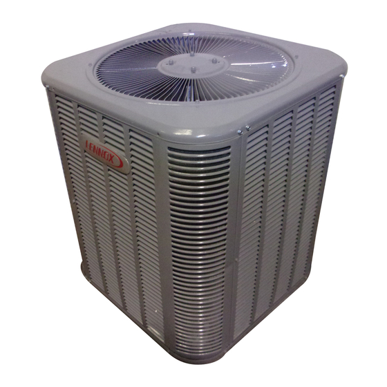
The 13ACX is a high efficiency residential split−system con-
densing unit, which features a scroll compressor and de-
signed for R−410A refrigerant. 13ACX units are available in
sizes ranging from 1−1/2 through 5 tons. The series is de-
signed for use with an expansion valve in the indoor unit.
This manual is divided into sections which discuss the major
components, refrigerant system, charging procedure, main-
tenance and operation sequence.
Information contained in this manual is intended for use by
qualified service technicians only. All specifications are sub-
ject to change.
IMPORTANT
Operating pressures of this R−410A unit are higher
than pressures in R−22 units. Always use service
equipment rated for R−410A.
WARNING
Improper installation, adjustment, alteration, service
or maintenance can cause property damage, person-
al injury or loss of life. Installation and service must
be performed by a qualified installer or service
agency.
WARNING
Warranty will be voided if covered equipment is re-
moved from original installation site. Warranty will
not cover damage or defect resulting from:
Flood, wind, lightning, or installation and operation in
a corrosive atmosphere (chlorine, fluorine, salt, re-
cycled waste water, urine, fertilizers, or other damag-
ing chemicals).
Corp. 0612−L2
Revised 06−2007
13ACX SERIES UNITS
General
Specifications / Electrical Data
I Application
II Unit Components
III Refrigeration System
IV Charging
VI Maintenance
VII Wiring and Sequence of Operation
Page 1
13ACX
TABLE OF CONTENTS
. . . . . . . . . . . . . . . . . . . . . . . . . . .
. . . . . . . .
. . . . . . . . . . . . . . . . . . . . . . . .
. . . . . . . . . . . . . . . . . .
. . . . . . . . . . . . . .
. . . . . . . . . . . . . . . . . . . . . . . .
. . . . . . . . . . . . . . . . . . . . .
©2006 Lennox Industries Inc.
Page 1
Page 2
Page 3
Page 3
Page 6
Page 7
Page 13
.
Page 14
Advertisement
Table of Contents

Related Manuals for Lennox 13ACX−018


Summary of Contents for Lennox 13ACX−018
- Page 1 ..... Page 13 cycled waste water, urine, fertilizers, or other damag- ing chemicals). VII Wiring and Sequence of Operation Page 14 ©2006 Lennox Industries Inc. Page 1...
- Page 2 SPECIFICATIONS General Model No. 13ACX−018 13ACX−024 13ACX−030 13ACX−036 13ACX−042 13ACX−048 13ACX−060 Data −2 units Nominal Tonnage (kW) 1.5 (5.3) 2 (7.0) 2.5 (8.8) 3 (10.6) 3.5 (12.3) 4 (14.1) 5 (17.6) Connections Liquid line o.d. − in. (mm) 3/8 (9.5) 3/8 (9.5) 3/8 (9.5) 3/8 (9.5)
- Page 3 3 -1/2, 4 and 5 ton capacities. All major components (indoor (C12) blower and coil) must be matched according to Lennox rec- ommendations for the compressor to be covered under war- ranty. Refer to the Engineering Handbook for approved sys-...
- Page 4 ORBITING SCROLL from the stationary scroll. The liquid is worked toward the center TIPS SEALED BY DISCHARGE PRESSURE of the scroll and is discharged. If the compressor is replaced, FIGURE 5 conventional Lennox cleanup practices must be used. Page 4...
- Page 5 SUCTION SUCTION INTERMEDIATE PRESSURE ORBITING SCROLL CRESCENT SHAPED GAS POCKET STATIONARY SCROLL SUCTION POCKET FLANKS SEALED BY CENTRIFUGAL SUCTION SUCTION FORCE MOVEMENT OF ORBIT DISCHARGE HIGH PRESSURE GAS POCKET FIGURE 6 C − Condenser Fan Motor All units use single−phase PSC fan motors which require a run capacitor.
- Page 6 Field refrigerant piping consists of liquid and suction lines service port from the condensing unit (sweat connections) to the indoor evaporator coil (sweat connections). Use Lennox L15 insert hex (sweat) series line sets as shown in table 1. wrench here...
- Page 7 IV − CHARGING Using an Electronic Leak Detector 1 − Connect a cylinder of R−410A to the center port of the manifold gauge set. Connect manifold gauge to service WARNING valve port. R−410A refrigerant can be harmful if it is inhaled. 2 −...
- Page 8 5 − Evacuate the line set and indoor unit to an absolute 7 − Shut off the nitrogen cylinder and remove the manifold pressure of 23,000 microns (29.01 inches of mercury). gauge hose from the cylinder. Open the manifold gauge During the early stages of evacuation, it is desirable to valves to release the nitrogen from the line set and in- close the manifold gauge valve at least once to deter-...
- Page 9 Pre−Charge Maintenance Checks TABLE 2 Normal Operating Pressures (TXV) Use this table to perform maintenance checks; it is not a procedure for charging the system. Minor variations in these pressures may be due to differences in IMPORTANT installations. Significant deviations could mean that the system is not properly charged or that a problem exists with some component in the system.
- Page 10 Determining Charge Method START: Determine how refrigerant is metered WHEN TO CHARGE? Warm weather best Which Can charge in colder weather metering CHARGE METHOD? Determine by: device? Metering device type Outdoor ambient temperature REQUIREMENTS: Sufficient heat load in structure 40ºF 65ºF 39ºF 64ºF...
- Page 11 Superheat RFC Charge 1.. Confirm proper airflow across coil using figure START: Measure outdoor ambient temperature 2.. Check liquid and vapor line pressures and ABOVE compare unit pressures with Normal Operating USE WEIGH-IN METHOD Pressures listed in table 2. Outdoor Weigh-in or remove refriger- (Note: Table 2 is a general guide.
- Page 12 Approach TXV Charge 1.. Confirm proper airflow across coil using figure START: Measure outdoor ambient temperature 2.. Check liquid and vapor line pressures and ABOVE compare unit pressures with Normal Operat- USE WEIGH-IN METHOD DO NOT CHARGE UNIT ing Pressures listed in table 2 on page 9. Outdoor (Table 2 is a general guide.
- Page 13 5.Check for correct voltage at unit (unit operating). V − MAINTENANCE 6.Check amp−draw outdoor fan motor. WARNING Unit nameplate _________ Actual ____________ . NOTE − If owner reports insufficient cooling, the unit should Electric shock hazard. Can cause injury be gauged and refrigerant charge checked. See refrigerant or death.
- Page 14 VI − WIRING DIAGRAMS AND SEQUENCE OF OPERATION 13ACX NOTE− The thermostat used may be electromechanical or electronic. NOTE− Transformer in indoor unit supplies power (24 VAC) to the thermostat and outdoor unit controls. COOLING: 1− Cooling demand initiates at Y1 in the thermostat. 2−...
Need help?
Do you have a question about the 13ACX−018 and is the answer not in the manual?
Questions and answers