Table of Contents
Advertisement
Quick Links
Download this manual
See also:
Service & Parts Manual
BIELA14 Series
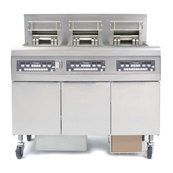
Gen II LOV
Service Manual
This manual is updated as new information and models are released. Visit our website for the latest manual.
This equipment chapter is to be installed in the Fryer Section of the Equipment Manual.
FOR YOUR SAFETY
Do Not Store or use gasoline or other
flammable vapors and liquids in the vicinity
of this or any other appliance.
*8196446*
Part Number: FRY_SM_8196446 02/2016
Original Instructions
™
Electric Fryer
Advertisement
Table of Contents
Troubleshooting

Related Manuals for Frymaster Gen II LOV


Summary of Contents for Frymaster Gen II LOV
- Page 1 BIELA14 Series ™ Gen II LOV Electric Fryer Service Manual This manual is updated as new information and models are released. Visit our website for the latest manual. This equipment chapter is to be installed in the Fryer Section of the Equipment Manual.
- Page 2 EQUIPMENT OTHER THAN AN UNMODIFIED NEW OR RECYCLED PART PURCHASED DIRECTLY FROM FRYMASTER DEAN, OR ANY OF ITS FACTORY AUTHORIZED SERVICERS, AND/OR THE PART BEING USED IS MODIFIED FROM ITS ORIGINAL CONFIGURATION, THIS WARRANTY WILL BE VOID. FURTHER, FRYMASTER ...
- Page 3 Adequate means must be provided to limit the movement of this appliance without depending on or transmitting stress to the electrical conduit. A restraint kit is provided with the fryer. If the restraint kit is missing contact your local KES. DANGER This fryer has a power cord (three‐phase) for each frypot and a single five‐wire cord for the entire system. Prior to movement, testing, maintenance and any repair on your Frymaster fryer; disconnect ALL electrical power cords from the electrical power supply . DANGER Keep all items out of drains. Closing actuators may cause damage or injury. ...
- Page 4 3. If any parts, except fuses and filter O-rings, become defective during the first two years after installation date, Frymaster will also pay straight-time labor costs up to two hours to replace the part, plus up to 100 miles/160 km of travel (50 miles/80 km each way).
-
Page 5: Electrical Power Specifications
no fryer will be warranted under the ten-year program for which a proper start-up form has not been received. This warranty also does not cover: transportation or travel over 100 miles/160 km (50 miles/80 km each way), or travel over two hours;... -
Page 6: Table Of Contents
BIELA14 SERIES GEN II LOV™ ELECTRIC FRYERS SERVICE TABLE OF CONTENTS CAUTIONARY STATEMENTS ............................i WARRANTY STATEMENT ............................ii ELECTRICAL POWER SPECIFICATIONS ....................... iii CHAPTER 1: Service Procedures General ................................1-1 Replacing a Computer ............................1-1 Replacing Component Box Components .......................1-1 Replacing a High-Limit Thermostat ......................1-3 Replacing a Temperature Probe ........................1-3... -
Page 7: Chapter 1: Service Procedures
BIELA14 SERIES GEN II LOV™ ELECTRIC FRYERS CHAPTER 1: SERVICE PROCEDURES 1.1 General Before performing any maintenance on your Frymaster fryer, disconnect the fryer from the electrical power supply. WARNING To ensure the safe and efficient operation of the fryer and hood, the electrical plug for the 120-volt line, which powers the hood, must be fully engaged and locked in its pin and sleeve socket. - Page 8 3. Remove the two screws from the upper corners of the computer and allow the computer to swing down. 4. Unplug the wiring harnesses and disconnect the grounding wires from the terminals on the back of the computer. Remove the computer assembly by lifting it from the hinge slots in the control panel frame.
-
Page 9: Replacing A High-Limit Thermostat
1.4 Replacing a High-Limit Thermostat 1. Remove the filter pan and lid from the unit. Drain the frypots into an McDonald’s Shortening Disposal Unit (MSDU) or other appropriate METAL container using the computer “drain to pan option” or using the MIB board in manual mode. DANGER DO NOT drain more than one full frypot or two split frypots into the MSDU at one time. - Page 10 4. Locate the red (or yellow) and white wires of the temperature probe to be replaced. Note where the leads are connected prior to removing them from the connector. Unplug the 12-pin connector C-6 and using a pin-pusher push the pins of the temperature probe out of the connector. 5.
-
Page 11: Replacing A Heating Element
Replacing a Heating Element 1. Perform steps 1-5 of section 1.5, Replacing a Temperature Probe. 2. Disconnect the wire harness containing the probe wiring, where the temperature probe is attached to the element being replaced. Using a pin pusher, disconnect the probe wires from the 12-pin connector. - Page 12 Index Marker marks Position 1 Full vat element wire routing Pull the element wires through the bushings on either side of the frypot and down the back. Element wires should be routed to the right of the ATO temperature probe on the back wall of the frypot.
-
Page 13: Replacing Contactor Box Components
8. Reconnect the element connector ensuring that the latches lock. 9. Insert the temperature probe leads into the 12-pin wiring harness connector (see illustration below). For full-vat units or the right half of a dual-vat unit, the red lead goes into position 3 and the white into position 4. -
Page 14: Replacing A Frypot
4. The contactors and relays are held on by threaded pin studs so that only removal of the nut is required to replace the component. 5. After performing necessary service, reverse steps 1-4 to return the fryer to operation. Left and right views of mechanical contactor box components. Sometimes it is necessary to remove the entire contactor box to repair. - Page 15 3. Slide the metal bezel up to release the bottom tabs, then slide the bezel down to disengage the upper tabs. 4. Remove the two screws from the upper corners of the computers and allow them to swing down (see illustration and photo on page 1-1). 5.
-
Page 16: Built-In Filtration System Service Procedures
23. Position the element tube assembly in the frypot and reinstall the machine screws and nuts removed in step 19. 24. Reconnect the oil return flexlines to the frypot, and replace aluminum tape, if necessary, to secure heater strips to the flexlines. 25. -
Page 17: Replacing The Filter Motor, Filter Pump And Related Components
Solidified shortening in the pan or filter Sediment Particle lines, or Attempting to filter unheated oil or shortening (cold oil is more viscous, Oil Flow overloading the pump motor and causing it to overheat). If the motor runs but the pump does not return oil, there is a blockage in the pump. - Page 18 Once replaced, reconnect the power. When replacing a filter relay in the left component box, ensure the 24VDC relay (8074482) is used. Similar Frymaster fryers use a 24VAC relay, which can lead to confusion. The 24VDC is used in the LOV™ fryer. 1-12...
-
Page 19: Ato (Automatic Top-Off) Service Procedures
1.10 ATO (Automatic Top-off) Service Procedures The automatic top-off system is activated when the oil level falls below a sensor in the rear of the frypot. The signal is sent to the ATO board to engage the return actuator to the frypot and turn on the ATO pump. The pump draws oil from the JIB (Jug In Box) through the rear return manifold into the rear of the frypot. - Page 20 Problem Probable Causes Corrective Action Ensure JIB has oil. Clean crumbs from opening surrounding sensor. Check to see that fryer is heating. Fryer temperature must be at setpoint. Check Empty JIB. probe resistance. If probe is bad, replace the probe. Crumb build up around sensor.
- Page 21 1.10.2 ATO (Automatic Top-Off) Board Pin Positions and Harnesses Wire Connector From/To Harness # Function Voltage Color RTI Add Solenoid 24VAC Black 24VAC Ret ATO Pump Relay 24VAC Black 24VAC Ret JIB Reset Switch 16VDC JIB Low Reset Black 8074671 RTI Add Solenoid 24VAC 24VAC...
-
Page 22: Replacing The Ato Board, Lon Gateway, Ato Pump Relay Or Transformer
1.10.3 Replacing the ATO board, LON Gateway, ATO pump relay or Transformers Disconnect the fryer from the electrical power supply. Locate the ATO box (see Figure 1 on page 12), behind the JIB (Jug In Box). Remove the cover to expose the transformers, relay and LON gateway (if installed) (see Figure 2). - Page 23 Buttons and LED’s Manual – This button is used to toggle between auto and manual filtration mode. A corresponding LED is lit when in Manual mode. When pressed, a message will be sent to all vats, indicating the mode has changed. The following buttons are inoperable in auto mode: Select - This button is used to scroll through available vats, choosing one to be manually filtered.
-
Page 24: Mib Display Diagnostics
1.11.2 MIB (Manual Interface Board) Troubleshooting Problem Probable Causes Corrective Action Ensure filter pan is fully inserted into fryer. Filter pan out of position. If the MIB board displays a “P” the pan is Oil level too low. not fully engaged into the pan switch. Ensure MIB board is not in Ensure the oil level is above the top oil manual mode. - Page 25 Problem Probable Causes Corrective Action Ensure the CAN bus system is terminated at BOTH ENDS (on the M3000 connector J6 and on the ATO board connector J10) with a resistor equipped 6-pin connector. With the computer OFF, press TEMP button and ensure the AIF version appears.
- Page 26 1.11.3 MIB (Manual Interface Board) Pin Positions and Harnesses Connector From/To Harness # Pin # Function Voltage Wire Color Ground Black CAN Lo CAN Hi White M3000 J7 8074546 Ground Black CAN Lo CAN Hi White AIF J4 8074547 5VDC+ 5VDC Black 24VDC...
- Page 27 1.11.4 MIB (Manual Interface Board) Display Diagnostics DISPLAY EXPLANATION Drain Vat # (The vat number is followed by Drain valve on vat # is open an “L” to indicate left side of a split vat or an “r” to indicate the right side of a split vat or a full vat.) Vat # (The vat number is followed by Drain valve on vat # is closed...
-
Page 28: Replacing The Mib Board
1.11.5 MIB (Manual Interface Board) Display Characters A – Auto Mode – Auto Filtration enabled. E – Drain or return valve is not in desired state. The display will alternate between E and the corresponding vat number. Ensure the actuator is plugged in and an error does not exist. –... -
Page 29: Rti Service Issues
1.12 RTI Service Issues 1.12.1 RTI MIB Tests The LOV™ fryer will ONLY operate with RTI systems that have the new RTI updated three-pole float switch. If the float switch is the older two-pole switch, call RTI. These float switches are polarity specific which may short to ground and damage an MIB board. -
Page 30: Rti Lov Wiring
1.12.2 RTI LOV™ Wiring 1.12.3 Frymaster LOV™ Fryer and RTI Bulk Oil System Plumbing Schematic 1-24... -
Page 31: Rti Lov Quick Reference
1.12.4 RTI LOV™ TEST QUICK REFERENCE DISPOSE TO WASTE, REFILL VAT FROM BULK: 1. Hold down “Filter” button until computer beeps twice. 2. Scroll down to “Dispose” using “Info" button then press “” button. 3. “Dispose? Yes/No” is displayed.* 4. Press “” to dispose of oil in pot. 5. - Page 32 8. “Filling” is displayed during fill. 9. Release button to stop filling. 10. “Continue Filling? Yes/No” is displayed. 11. Press “” to exit. FILL JUG FROM BULK:* 1. When “Orange” indicator light is on, the top-off jug is empty. 2. To refill jug press and hold the orange reset button above the jug until the jug is full. 3.
-
Page 33: Aif (Automatic Intermittent Filtration) Service Procedures
1.13 AIF (Automatic Intermittent) Filtration Service Procedures The AIF (Automatic Intermittent Filtration) board controls the actuators that open and close the drain and return valve. The AIF boards are located inside a protective housing under each frypot (see Figure 13). Figure 13 1.13.1 AIF Troubleshooting Problem... - Page 34 1.13.2 AIF (Auto Intermittent Filtration) Actuator Board Pin Positions and Harnesses Wire Connector From/To Harness PN Function Voltage Color Ret + (Open) 24VDC Black Ret – (Closed) 24VDC FV Return Actuator Ret Position Purple Ground White Ground White FV AIF RTD FV - Temp Ground White...
-
Page 35: Replacing An Aif Board
1.13.3 Replacing an AIF (Automatic Intermittent Filtration) board Disconnect the fryer from the electrical power supply. Locate the AIF board to be replaced under a frypot. Mark and unplug the harnesses. The AIF board assembly is held in place with one screw in the front of the assembly (see Figure 14). -
Page 36: M3000 Computer Service Procedures
1.13.5 Replacing a Rotary Actuator Disconnect the fryer from the electrical power supply. Locate the actuator to be replaced and mark and unplug the actuator. The actuators are held in place by two allen screws. Loosen the allen screws. It may be necessary to remove a gas line to the burner when removing a drain actuator. - Page 37 Problem Probable Causes Corrective Action M3000 display shows Press 1234 to enter setup and set energy type Wrong energy type selected in setup. ENERGY for electric. MISCONFIGURED M3000 display shows EXCEPTION Press 1234 to enter setup and reconfigure the An error has occurred. ERROR with the computer.
- Page 38 Problem Probable Causes Corrective Action A. Problem with the temperature A. This indicates a problem within the measuring circuitry including the probe. temperature measuring circuitry. Check B. Damaged computer wiring harness or resistance of probe, if faulty replace M3000 display shows connector.
- Page 39 Problem Probable Causes Corrective Action A filter error has occurred due to dirty or clogged filter pad or paper, clogged filter M3000 display shows pump, filter pump thermal overload, Follow the steps in the flowchart in section IS VAT FULL? improperly installed filter pan components, 1.14.5.
-
Page 40: Service Required Errors
1.14.3 Service Required Errors A SERVICE REQUIRED error alternating with YES displays on the computer. After YES is pressed the alarm is silenced. The computer displays an error message from the list below three times with the location of the error. Then the computer displays SYSTEM ERROR FIXED? YES/NO. If yes is chosen, enter code 1111. -
Page 41: Error Log Codes
1.14.4 Error Log Codes Refer to page 1-39, level 2 program for access to the E-log. The ten most recent errors are listed from A-J, with A being the most recent error. Code ERROR MESSAGE EXPLANATION REMOVE DISCARD (Right) A product cook is started on the right side of a split vat or in a full vat that has a different setpoint other than the current vat temperature. -
Page 42: Tech Mode
1.14.5 Tech Mode Tech mode allows technicians to reset all passwords set in levels one and two and change when the fryer calls for a filter pad change. The default is 25 hours. simultaneously for TEN seconds until three chirps sound and TECH 1. -
Page 43: M3000 Filter Error Flowchart
1.14.6 M3000 Filter Error Flowchart MESSAGE NORMAL DISPLAYED OPERATION RESUMES Call an Authorized Repair Technician SIXTH CONSECUTIVE FILTER ERROR TECH Fryer returns to ENTERS cook mode for 15 CODE minutes. Change filter pad and ensure filter pan is Fryer returns to pulled out for a cook mode for 4 minimum of 30... -
Page 44: M3000 Menu Summary Tree
1.14.7 M3000 Menu Summary Tree Reflected below are the major programming sections in the M3000 and the order in which submenu headings will be found under the sections in the Installation and Operation Manual. See section 4.10.2 Adding New Menu Items See section 4.10.3 Storing Menu Items in Product Buttons See section 4.10.4... -
Page 45: M3000 Board Pin Positions And Harnesses
1.14.8 M3000 Board Pin Positions and Harnesses Connector From/To Harness PN Function Voltage Wire Color SD Card 12VAC In 12VAC Ground 12VAC In 12VAC FV Heat Demand V Relay 12VDC DV Heat Demand R/H B/L 12VDC Black Analog Ground L/H B/L 12VDC 8074199 Interface... -
Page 46: Loading And Updating Software Procedures
1.15 Loading and Updating Software Procedures Updating the software takes approximately 30 minutes. The software only needs to be loaded in ONE computer and it will update all the computers and boards in the system. To update the software, follow these steps carefully: 1. -
Page 47: Data Network Flowchart
1.16 BIELA14 Series LOV™ Data Network Flowchart 1-41... -
Page 48: Interface Board Diagnostic Chart
1.17 Interface Board Diagnostic Chart The following diagram and charts provide ten quick system checks that can be performed using only a multimeter. Diagnostic LED Legend CMP indicates power from 12V transformer indicates power from 24V transformer (RH) indicates output (closed) from right latch relay (LH) indicates output (closed) from left latch relay... -
Page 49: Probe Resistance Chart
1.18 Probe Resistance Chart Probe Resistance Chart For use with fryers manufactured with Minco Thermistor probes only. OHMS OHMS OHMS OHMS OHMS 1059 1204 1350 1493 1634 1070 1216 1361 1503 1644 1080 1226 1371 1514 1654 1091 1237 1381 1524 1664 1101... - Page 50 FRYMASTER 8700 LINE AVENUE, SHREVEPORT, LA 71106‐6800 318‐865‐1711 800‐551‐8633 844‐724‐CARE (2273) WWW.FRYMASTER.COM EMAIL: SERVICE@FRYMASTER.COM *8196446* Every new piece of Manitowoc Foodservice equipment comes with KitchenCare™ and you choose the level of service that meets your operational needs from one restaurant to multiple locations. StarCare – Warranty & lifetime service, certified OEM parts, global parts inventory, performance audited ExtraCare –...
Need help?
Do you have a question about the Gen II LOV and is the answer not in the manual?
Questions and answers