Miele CS 1112 Operating And Installation Instructions
Ceramic hobs
Hide thumbs
Also See for CS 1112:
- Operating and installation instructions (52 pages) ,
- User manual (45 pages) ,
- Operating and installation manual (52 pages)
Table of Contents

Related Manuals for Miele CS 1112


Summary of Contents for Miele CS 1112
- Page 1 Operating and installation instructions Ceramic hobs To avoid the risk of accidents or damage to the appliance it is essential to read these instructions before it is installed and used for the first time. en-GB M.-Nr. 07 138 350...
-
Page 2: Table Of Contents
Contents Warning and Safety instructions................ 4 Caring for the environment ................ 13 Guide to the appliance .................. 14 Hob........................14 CS 1112...................... 14 CS 1122...................... 15 CS 1134...................... 16 Indicators....................... 16 Cooking zones....................... 17 Using for the first time .................. 18 Cleaning the hob for the first time................. - Page 3 Contents Installation notes .................... 35 Building-in dimensions .................. 36 CS 1112......................... 36 CS 1122......................... 37 CS 1134......................... 38 Building-in several CombiSets ................ 39 Installation...................... 41 Electrical connection .................. 45 Wiring diagram CS 1134 ..................47 After sales service, data plate, guarantee ............ 48...
-
Page 4: Warning And Safety Instructions
They contain important notes on installation, safety, use and maintenance. Miele cannot be held liable for damage caused by non-compliance with these instructions. Keep these instructions in a safe place and ensure that new users... - Page 5 Warning and Safety instructions Correct application This hob is intended for domestic use and use in other similar en- vironments. This hob is not intended for outdoor use. It is intended for domestic use only to cook food and keep it warm.
- Page 6 Warning and Safety instructions Safety with children Children under 8 years of age must be kept away from the hob unless they are constantly supervised. Children 8 years and older may only use the hob unsupervised if they have been shown how to use it in a safe way and can recognise and understand the consequences of incorrect operation.
- Page 7 Unauthorised installation, maintenance and repairs can cause considerable danger for the user. Installation, maintenance and re- pairs must only be carried out by a Miele authorised technician. Do not use a damaged appliance. It could be dangerous. Check the hob for visible signs of damage.
- Page 8 Warning and Safety instructions Miele can only guarantee the safety of the appliance when genu- ine original Miele replacement parts are used. Faulty components must only be replaced by Miele spare parts. The hob is not intended for use with an external timer switch or a remote control system.
- Page 9 Warning and Safety instructions Correct use The hob gets hot when in use and remains hot for a while after be- ing switched off. There is a danger of burning until the residual heat indicators go out. Due to the high temperatures radiated, objects left near the hob when it is in use could catch fire.
- Page 10 Warning and Safety instructions You could burn yourself on the hot hob. Protect your hands with heat-resistant pot holders or gloves when handling hot pots and pans. Do not let them get wet or damp, as this causes heat to trans- fer through the material more quickly with the risk of scalding or burning yourself.
- Page 11 Warning and Safety instructions Aluminium pans or pans with an aluminium base can cause metal- lic, shiny marks to appear on the ceramic surface. These marks can be removed using a ceramic and stainless steel hob cleaner (see "Cleaning and care"). ...
- Page 12 Warning and Safety instructions Cleaning and care Do not use a steam cleaning appliance to clean this hob. The steam could reach electrical components and cause a short cir- cuit.
-
Page 13: Caring For The Environment
/ recycling centre for electrical and electronic ap- pliances, or contact your dealer or Miele for advice. You are also respons- ible by law for deleting any personal data that may be stored on the appli- ance being disposed of. Please ensure... -
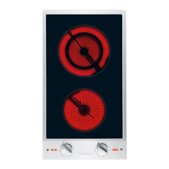
Page 14: Guide To The Appliance
Guide to the appliance CS 1112 a Double circle zone b Single circle zone c Cooking zone symbols d Indicators Cooking zone controls f Front g Back... - Page 15 Guide to the appliance CS 1122 a Extended zone b Single circle zone c Cooking zone symbols d Indicators Cooking zone controls f Front g Back...
-
Page 16: Indicators
Guide to the appliance CS 1134 ac Double circle zone bd Single circle zone e Cooking zone symbols f Indicators Cooking zone controls g Front left h Back left i Back right j Front right Indicators k In-operation indicator l Outer zone switched on m Residual heat indicator... -
Page 17: Cooking Zones
Guide to the appliance Cooking zones Cooking CS 1112 CS 1122 zone Ø in cm Ø in cm Rating in Watts Rating in Watts for 230 V for 230 V 14.5 1200 14.5 1200 10.0 / 18.0 700 / 1800 18.0 / 1500 / 18.0 x 26.5... -
Page 18: Using For The First Time
Using for the first time Please stick the extra data plate for Switching on the hob for the the appliance supplied with this doc- first time umentation in the space provided in The metal components have a protect- the "After sales service, data plate, ive coating which when heated for the guarantee"... -
Page 19: How The Cooking Zones Work
How the cooking zones work Single circle cooking zones have one Single circle zone heating element, whilst double circle cooking zones and extended zones have two. Depending on model, the heating elements may be separated by an isolating ring. Each cooking zone has overheating protection (a temperature limiter), which stops the ceramic surface from becom- ing too hot (see "Overheating protec-... -
Page 20: Pans
Pans Most suitable: Pans with a thick base – Often the maximum diameter quoted which is very slightly concave when by manufacturers refers to the dia- cold. When heated, the base flattens to meter of the top rim of the pot or rest evenly on the hob, optimising the pan. -
Page 21: Tips On Saving Energy
Tips on saving energy – Check that the diameter of the pan base is wide enough for the cooking zone so that heat is not lost unneces- sarily. – Use a pan lid whenever possible to minimize heat loss. – Select a smaller pan when cooking small quantities. -
Page 22: Settings
Settings Setting range Melting butter, chocolate, etc. Dissolving gelatine Making yoghurt Thickening sauces containing egg yolk and butter Warming small quantities of liquid Keeping food warm that sticks easily Cooking rice Warming liquid and semi-solid food 3–5 Thickening custard and sauces, e.g. hollandaise Making porridge Cooking omelettes, lightly fried eggs Steaming fruit... -
Page 23: Operation
Operation Cooking zone controls Switching off Turn the cooking zone controls with a The hobs have different types of con- trols: stop point anti-clockwise to 0. Turn the cooking zone controls – Controls with the symbol have a stop point. -
Page 24: Switching On An Extended Zone/Outer Ring
Operation Switching on an extended zone/outer ring Double circle and extended zones have a second heating element that can be switched on. Activating Turn the control clockwise past "12" to the symbol. Turn the control anti-clockwise to the setting you want. Deactivating ... -
Page 25: Safety Features
Safety features Overheating protection Each zone is equipped with overheating protection (internal temperature limiter). This switches the cooking zone heating off automatically before it overheats. As soon as the cooking zone has cooled down, the heating automatically switches back on again. The overheating mechanism can be triggered by: –... -
Page 26: Cleaning And Care
Cleaning and care Allow the CombiSet to cool down Danger of burning. before cleaning. The cooking zones must be switched off. The hob must have cooled down. The CombiSet and accessories should be cleaned after each use. Danger of injury. -
Page 27: Ceramic Surface
Wipe all coarse soiling off using a damp cloth. Stubborn soiling may need to be removed with a shielded scraper blade. Then clean the hob with Miele ceramic and stainless steel hob cleaner (see "Optional accessories") or a suitable proprietary ceramic hob cleaning agent applied with kitchen paper or a clean cloth. -
Page 28: Stainless Steel Frame/Control Panel
Cleaning and care Stainless steel frame/control panel Clean the frame and the control panel with a solution of warm water and a little washing-up liquid applied with a soft sponge. You can also use a ceramic and stain- less steel cleaning agent. We recom- mend also using a stainless steel condi- tioning agent to help prevent resoiling (see "Optional accessories). -
Page 29: Problem Solving Guide
Danger of injury. Installation, maintenance and repairs may only be carried out by a suitably qualified and competent person. Repairs and other work by unqualified persons could be dangerous. Miele can- not be held liable for unauthorised work. Do not attempt to open the casing of the CombiSet yourself. -
Page 30: Optional Accessories
These products can be ordered through the Miele Webshop. Removes heavy soiling, limescale de- posits and aluminium residues These can also be ordered from Miele (see end of this booklet for contact de- Stainless steel conditioning tails) or from your Miele dealer. -
Page 31: Safety Instructions For Installation
Safety instructions for installation Fit the wall units and cooker hood before fitting the CombiSet to avoid dam- aging it. The veneer or laminate coatings of worktops (or adjacent kitchen units) must be treated with 100 °C heat-resistant adhesive which will not dissolve or distort. -
Page 32: Safety Distances
Safety distances Safety distance above the CombiSet A minimum safety distance must be maintained between the CombiSet and the cooker hood above it. See the cooker hood manufacturer's operating and installation instructions for details. If the manufacturer's instructions are not available for the cooker hood a min- imum safety distance of at least 760 mm must be maintained, or if any flammable objects (e.g. - Page 33 CS 1212 / CS 1212-1 CS 1221 / CS 1221-1 CS 1234 / CS 1234-1 CS 1223 CS 1222 Recommended 50 mm CS 1112 CS 1122 CS 1134 CS 1326 CS 1327 CS 1411 100 mm CS 1012 / CS 1012-1...
- Page 34 Safety distances Safety distance when installing the appliance near a wall with additional niche cladding A minimum safety distance must be maintained between the worktop cut-out and any niche cladding to protect it from heat damage. If the niche cladding is made from a combustible material (e.g. wood) a minimum safety distance ...
-
Page 35: Installation Notes
Installation notes Seal between the CombiSet Tiled worktop and the worktop Grout lines and the hatched area un- derneath the CombiSet frame must be smooth and even. If they are not the Do not use sealant between the CombiSet will not sit flush with the CombiSet and the worktop. -
Page 36: Building-In Dimensions
Building-in dimensions CS 1112 a Spring clamps b Front c Casing depth d Casing depth including mains connection box with mains connection cable, L = 2000 mm... - Page 37 Building-in dimensions CS 1122 a Spring clamps b Front c Casing depth d Casing depth including mains connection box with mains connection cable, L = 2000 mm...
- Page 38 Building-in dimensions CS 1134 a Spring clamps b Front c Casing depth d Casing depth including mains connection box with mains connection cable, L = 2000 mm...
-
Page 39: Building-In Several Combisets
Building-in several CombiSets Example: 3 CombiSets a Spring clamps b Spacer bars c Gaps between spacer bars and worktop d Cover strips e CombiSet width minus 8 mm f CombiSet width g CombiSet width minus 8 mm h Worktop cut-out... - Page 40 Building-in several CombiSets Calculating the worktop cut-out The frames of the CombiSets overlap the worktop at the outside right and left by 8 mm on each side. Add up the widths of the CombiSets and subtract 16 mm from this figure. Example: 288 mm + 288 mm + 380 mm = 956 mm - 16 mm = 940 mm The CombiSets are 288 mm, 380 mm or 576 mm wide depending on model (see...
-
Page 41: Installation
Installation Preparing the worktop Make the worktop cut-out as shown in "Building-in dimensions" or as cal- culated (see Building-in several CombiSets). Observe the safety dis- tances (see "Safety distances"). Wooden worktops Seal the cut surfaces with a suitable sealant to avoid swelling caused by moisture. - Page 42 Installation Natural stone worktops You will need heavy duty double-side tape (not supplied) to secure the spring clamps and spacer bars. Apply silicone to the side and lower edges of the spring clamps and the spacer bars . Then fill gap between spacer bar ...
- Page 43 Installation Building in several CombiSets Installation with a downdraft extractor Push the built-in CombiSet to the side until the holes in the spacer bar Please refer to the separate "Downdraft can be seen. extractor with CombiSet" instruction manual for details about installing a downdraft extractor with a CombiSet appliance.
- Page 44 Installation Connecting the CombiSet Connect the CombiSet(s) to the mains. Check that each CombiSet works. Removing the CombiSet If the CombiSet cannot be accessed from below, you will need a special tool to remove it. If the CombiSet can be accessed from below, push it out from below.
-
Page 45: Electrical Connection
Electrical connection CS 1112 / CS 1122 Danger of injury. Miele cannot be held liable for unau- All electrical work should be carried out by a suitably qualified and competent thorised installation, maintenance and repair work as this can be dan-... - Page 46 Electrical connection Connection Disconnecting from the mains AC 230 V, 50 Hz Danger of electric shock. The connection data is quoted on the After disconnection, ensure the ap- data plate. It must match the household pliance cannot be switched back on supply.
-
Page 47: Wiring Diagram Cs 1134
If the mains cable needs to be replaced it must be replaced with a special con- nection cable, type H 05 VV-F (PVC-in- (L3) sulated), available from Miele. 200 - 240 V~ The connection data is quoted on the 200 - 240 V~ data plate. -
Page 48: After Sales Service, Data Plate, Guarantee
N.B. A call-out charge will be applied to service visits where the problem could have been resolved as described in these instructions. When contacting your Dealer or Miele, please quote the model and serial number of your appliance. Data plate Space in which to stick the extra data plate supplied with the appliance. -
Page 49: Product Data Sheets
Information for domestic electric hobs In acc. with regulation (EU) No. 66/2014 MIELE Model name / identifier CS 1112 Number of cooking zones and/or areas For circular cooking zones: diameter of useful sur- 1. = Ø 145 mm face area/cooking zone 2. - Page 50 Product data sheets Information for domestic electric hobs In acc. with regulation (EU) No. 66/2014 MIELE Model name / identifier CS 1134 Number of cooking zones and/or areas For circular cooking zones: diameter of useful sur- 1. = Ø 100 / Ø 180 mm face area/cooking zone 2.
- Page 51 Tel: +971 4 3044 999 Tel: (01) 461 07 10, Fax: (01) 461 07 97 Fax: +971 4 3418 852 E-Mail: info@miele.ie, Internet: www.miele.ie 800-MIELE (64353) Manufacturer: Miele & Cie. KG E-Mail: info@miele.ae Internet: www.miele.ae Carl-Miele-Straße 29, 33332 Gütersloh, Germany...
- Page 52 CS 1112 / CS 1122 / CS 1134 en-GB M.-Nr. 07 138 350 / 11...
Need help?
Do you have a question about the CS 1112 and is the answer not in the manual?
Questions and answers