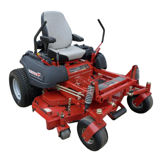
Ferris IS3000Z series Operator's Manual
Zero-turn riding mower
Hide thumbs
Also See for IS3000Z series:
- Operator's manual (19 pages) ,
- Operator's manual with setup instructions (44 pages) ,
- Operator's manual (39 pages)
Table of Contents
Advertisement
Advertisement
Table of Contents
Troubleshooting

Related Manuals for Ferris IS3000Z series


Summary of Contents for Ferris IS3000Z series
- Page 1 OPERATOR’S MANUAL IS3000Z Series Zero-Turn Riding Mower Serial No. 3631 & above Model Number: IS3000ZFKAV2561 3000ZFKAV2561CE IS3000ZXK27/61 IS3000ZLKAV2661 Ferris Industries 23462 5375 North Main Street Revision 01 Munnsville, NY 13409 Rev. 11/2004 800-933-6175 TP 100-7169-01-3Z-F...
-
Page 3: Table Of Contents
Table of Contents Safety Rules & Information ........2 Troubleshooting, Adjustments & Service ..22 Troubleshooting the Tractor........22 Identification Numbers ........5 Troubleshooting the Mower ........23 Safety Decals & Icons.........6 Seat Adjustment............24 Safety Interlock System........7 Ground Speed Control Lever Adjustment .....24 Features & Controls ..........8 Speed Balancing Adjustment........24 Control Functions............8 Neutral Adjustment ..........25... -
Page 4: Safety Rules & Information
Safety Rules & Information Read these safety rules and follow them closely. Failure to obey these rules could result in loss of control of unit, severe personal injury or death to you, or bystanders, or damage to property or equipment. This mowing deck is capable of amputating hands and feet and throwing objects. - Page 5 Safety Rules & Information 23. Use care when approaching blind corners, shrubs, Do Not trees or other objects that may obscure vision. 1. Avoid starting, stopping, or turning on a slope. If 24. To reduce fire hazard, keep unit free of grass, leaves tires lose traction (i.e.
- Page 6 Safety Rules & Information SERVICE AND MAINTENANCE 10. Let engine cool before storing and do not store near flame. To avoid personal injury or property damage, use 11. Stop and inspect the equipment if you strike an extreme care in handling gasoline. Gasoline is object.
-
Page 7: Identification Numbers
Identification Numbers Identification Numbers Identification Tag FERRIS FERRIS INDUSTRIES, INC. UNNSVILLE, NY 13409 ADE IN THE USA All Models SERIAL NO. ODEL NO. Model No.: XXXXXXXXXX Engine RPM: XXXX 200X LpA: XX dB(A) CE Models Vibration @ Wheels: Vibration @ Seat:... -
Page 8: Safety Decals & Icons
Safety Decals SAFETY DECALS This unit has been designed and manufactured to pro- All DANGER, WARNING, CAUTION and instructional vide you with the safety and reliability you would expect messages on your rider and mower should be carefully from an industry leader in outdoor power equipment read and obeyed. -
Page 9: Safety Interlock System
Safety Icons & Interlock System SAFETY ICONS SAFETY INTERLOCK Warning: Read Operator’s Manual. SYSTEM Read and understand the Operator’s Manual before using this machine. This unit is equipped with safety interlock switches. These safety systems are present for your safety, do not Danger: Thrown Objects. -
Page 10: Features & Controls
Features & Controls CONTROL FUNCTIONS The information below briefly describes the function of individual controls. Starting, stopping, driving, and mowing require the combined use of several controls applied in specific sequences. To learn what combination and sequence of controls to use for various tasks see the OPERATION section. Ground Speed Levers Seat Adjustment Lever The seat can be adjusted forward and back. - Page 11 Features & Controls Parking Brake Fuel Shut Off Valve Turning the handle to the desired position determines which tank will be supplying fuel. With the handle point- DISENGAGE Releases the parking brake. ing LEFT, it will draw fuel from the left-hand tank. With the handle pointing RIGHT, it will draw fuel from the ENGAGE Locks the parking brake.
-
Page 12: Operation
Operation GENERAL OPERATING SAFETY CHECKS BEFORE STARTING Before first time operation: • Check that crankcase is filled to full mark on dipstick. See the engine Operator’s Manual for instructions • Be sure to read all information in the Safety and and oil recommendations. -
Page 13: Starting The Engine
Operation WARNING MOWING 1. Engage the parking brake. Make sure the PTO If you do not understand how a specific control switch is disengaged, the motion control handles are functions, or have not yet thoroughly read the locked in the NEUTRAL position and the operator is FEATURES &... -
Page 14: Zero Turn Driving Practice
Operation ZERO TURN Smooth Travel DRIVING PRACTICE The lever controls of the Zero Turn rider are The lever controls of the Zero Turn rider are responsive, responsive . and learning to gain a smooth and efficient control of the The BEST method of rider’s forward, reverse, and turning movements will take handling the ground some practice. -
Page 15: Advanced Driving
Operation Practice Turning Around a Corner Practice Turning In Place While traveling forward allow one handle to gradually To turn in place, “Zero Turn,” gradually move one ground return back toward neutral. Repeat several times. speed control lever forward from neutral and one lever back from neutral simultaneously. -
Page 16: Attaching A Trailer
Operation ATTACHING A TRAILER The maximum weight of a towed trailer should be less than 300 lbs (138kg). Secure the trailer with an appro- priately sized clevis pin (A, Figure 9) and clip (B). Excessive towed loads can cause loss of traction and loss of control on slopes. -
Page 17: Storage
Operation STORAGE WARNING Temporary Storage (30 Days Or Less) Never store the unit, with gasoline in engine or fuel tank, in a heated shelter or in enclosed, Remember, the fuel tank will still contain some gasoline, poorly ventilated enclosures. Gasoline fumes may so never store the unit indoors or in any other area reach an open flame, spark or pilot light (such as where fuel vapor could travel to any ignition source. -
Page 18: Regular Maintenance
Regular Maintenance MAINTENANCE SCHEDULE & PROCEDURES The following schedule should be followed for normal care of your rider and mower. You will need to keep a record of your operating time. Determining operating time is easily accomplished by observing the elapsed time recorded by the hour meter. -
Page 19: Checking/Adding Fuel
Regular Maintenance CHECKING / ADDING FUEL WARNING To add fuel: Gasoline is highly flammable and must be handled with care. Never fill the tank when the 1. Remove the fuel cap (see A, Figure 2). engine is still hot from recent operation. Do not 2. -
Page 20: Check Engine Coolant Level
Regular Maintenance CHECK ENGINE COOLANT LEVEL WARNING The engine coolant level and quality should be checked PRESSURIZED SYSTEM before each use, when the engine is cool and off. Hot coolant can cause serious burns. Never open The cooling system is a closed type. Never open the the radiator cap. -
Page 21: Lubrication
Figure 15. Control Handle Pivots & Seat Pivots to apply grease to moving parts when grease fittings are not installed. Not all greases are compatible. Ferris Red Grease (P/N 22285) is recommended, automotive-type high- temperature, lithium grease may be used when this is not available. -
Page 22: Battery Maintenance
Regular Maintenance BATTERY MAINTENANCE WARNING Checking the Battery Fluid Be careful when handling the battery. Avoid spilling electrolyte. Keep flames and sparks away 1. Raise the seat plate to access battery. from the battery. 2. Remove the battery filler cap (A, Figure 19). Fluid When removing or installing battery cables, must be even with the split ring full mark. -
Page 23: Servicing The Mower Blades
Regular Maintenance SERVICING THE MOWER BLADES 1. Blades should be sharp and free of nicks and dents. If not, sharpen blades as described in following steps. 2. To remove blade for sharpening, use a 1” wrench on the flats of the spindle shaft while removing the blade mounting bolt with a 15/16”... -
Page 24: Troubleshooting Adjustments & Service
Troubleshooting Adjustments & Service TROUBLESHOOTING WARNING While normal care and regular maintenance will extend To avoid serious injury, perform maintenance on the life of your equipment, prolonged or constant use the tractor or mower only when the engine is may eventually require that service be performed to stopped and the parking brake engaged. -
Page 25: Troubleshooting The Mower
Troubleshooting, Adjustment & Service Rider Troubleshooting Continued. PROBLEM CAUSE REMEDY Engine runs, but rider will 1. Hydraulic release valve(s) 1. Turn valve(s) clockwise to close. not drive. in “open” position. 2. Belt is broken. 2. See Drive Belt Replacement. 3. Drive belt slips. 3. -
Page 26: Seat Adjustment
Troubleshooting, Adjustment & Service SEAT ADJUSTMENT See Figure 23. The seat can be adjusted forward and Seat Adjustment back. Move the lever forward, position the seat as Lever desired, and release the lever to lock the seat into posi- tion. GROUND SPEED CONTROL LEVER ADJUSTMENT The control levers can be adjusted in three ways. -
Page 27: Neutral Adjustment
Troubleshooting, Adjustment & Service NEUTRAL ADJUSTMENT If the tractor “creeps” while the ground speed control levers are locked in NEUTRAL, than it may be neces- sary to adjust the linkage rod. NOTE: Perform this adjustment on a hard, level surface such as a concrete floor. -
Page 28: Parking Brake Adjustment
Troubleshooting, Adjustment & Service PARKING BRAKE ADJUSTMENT FRONT 1. Disengage the PTO, stop the engine, block the front wheels, remove the ignition key, and engage the parking brake. 2" - 2-1/8" (5,0 - 5,4cm) 2. Locate the upper brake spring (A, Figure 28). 3. -
Page 29: Front Suspension Adjustment
Troubleshooting, Adjustment & Service FRONT SUSPENSION ADJUSTMENT INCREASE INCREASE DECREASE DECREASE The shock assembly can be adjusted to vary the amount of pre-load applied to the springs. This allows the oper- ator to customize the ride according to operator’s weight and/or operating conditions. -
Page 30: Pto Clutch Adjustment
Troubleshooting, Adjustment & Service Figure 33. Adjust PTO Clutch Window Adjustment Nut C. .016”-.018” (0,40-0,45mm) Feeler Gauge Figure 32. PTO Clutch Adjustment Adjustment Window (Qty. 3, one shown) Adjustment Nut PTO CLUTCH ADJUSTMENT WARNING Check the PTO clutch adjustment after the initial 25 hour To avoid serious injury, perform adjustments only break-in period and then after every 100 hours of opera- with engine stopped, key removed and tractor on... -
Page 31: Cutting Height Adjustment
Troubleshooting, Adjustment & Service CUTTING HEIGHT ADJUSTMENT WARNING Before checking mower, shut off PTO and engine. Allow all moving parts to stop. Remove ignition key, then disconnect the spark plug wire and fasten it away from the spark plug. The cutting height adjustment pin (A, Figure 34) controls the mower cutting height. -
Page 32: Deck Lift Rod Timing Adjustment
Troubleshooting, Adjustment & Service DECK LIFT ROD TIMING Inner Rod ADJUSTMENT 1. Park machine on a flat, level surface. Disengage the PTO, stop the engine and engage the parking brake. Rear tires must be inflated to 15 psi (1,03 bar); front tires to 25 psi (1,72 bar). -
Page 33: Deck Leveling Adjustment
Troubleshooting, Adjustment & Service DECK LEVELING ADJUSTMENT NOTE: Before adjusting the deck level, the deck lift rod timing must be checked and/or adjusted. 1. Park machine on a flat, level surface. Disengage the PTO, stop the engine and engage the parking brake. Rear tires must be inflated to 15 psi (1,03 bar);... -
Page 34: Hydraulic Pump Drive Belt Replacement
Troubleshooting, Adjustment & Service HYDRAULIC PUMP DRIVE BELT REPLACEMENT FRONT 1. Park the tractor on a smooth, level surface such as a concrete floor. Disengage the PTO, engage the parking brake, turn off the engine, and remove the ignition key. 2. -
Page 35: Mower Belt Replacement
Troubleshooting, Adjustment & Service MOWER BELT REPLACEMENT To avoid damaging belts, DO NOT PRY BELTS OVER PULLEYS. 1. Park the tractor on a smooth, level surface such as a concrete floor. Disengage the PTO, engage the parking brake, turn off the engine, and remove the ignition key. -
Page 36: Battery Service
Troubleshooting, Adjustment & Service BATTERY SERVICE 6. Charge the battery until fully charged (until the spe- cific gravity of the electrolyte is 1.250 or higher and the electrolyte temperature is at least 60° F). The WARNING best method of making certain a battery is fully charged, but not over charged, is to measure the Keep open flames and sparks away from the specific gravity of a cell once per hour. - Page 37 Troubleshooting, Adjustment & Service THIS HOOK-UP FOR NEGATIVE GROUND VEHICLES Starter Starter Switch Switch Jumper Cable Starting Discharged Vehicle Vehicle Battery Battery Jumper Cable To Ground Engine Block MAKE CERTAIN VEHICLES DO NOT TOUCH Figure 45. Jump Starting WARNING WARNING Any procedure other than the preceding could For your personal safety, use extreme care when result in:...
-
Page 38: Specifications
Specifications NOTE: Specifications are correct at time of printing and are subject to change without notice. * Actual sustained equipment horsepower will likely be lower due to operating limitations and environmental factors. ENGINE: CHASSIS: Fuel Tanks Capacity: 11 Gallons (41.6 L) Total 25 HP* Kawasaki Rear Wheels Tire Size: 24 x 12.00 -12... -
Page 39: Lawn Care
Lawn Care & Mowing Information GENERAL INFORMATION • Types of Grass, Climate and Conditions • How and When to Water, Fertilize & Aerate Proper mowing is an important part of maintaining your • How High to Mow the Grass lawn in the best possible condition. A healthy and well •... -
Page 40: Lawn Care & Mowing Information
Lawn Care & Mowing Information HOW HIGH TO Cut less than MOW THE GRASS Often cutting height is a Optimal matter of personal prefer- cutting point ence. Typically, you should at less than mow the grass when it is is 1/3 from top between three and five of grass blade... -
Page 41: When And How Often To Mow
Lawn Care & Mowing Information WHEN AND HOW OFTEN TO MOW The time of day and condition of the grass greatly affect the results you’ll get when mowing. For the best results, follow these guidelines: l Mow when the grass is between three and five inches high. -
Page 42: Mowing Methods
Lawn Care & Mowing Information MOWING METHODS Proper Broadcast Mowing Broadcasting, or side-discharging, disperses fine clip- pings evenly over the entire lawn. Many golf courses use this method. Your mower has a deep dish deck to allow freer circulation of clippings so they are broadcast evenly over the lawn. - Page 43 Lawn Care & Mowing Information TIPS On Dealing With Clippings • Reduce the evaporation of water from your lawn. • Provide a cushioning layer to reduce lawn wear. Clippings are beneficial to your lawn. A common mis- • Moderate soil temperature. conception about clippings is that they automatically •...
- Page 44 Lawn Care & Mowing Information SOLUTIONS FOR COMMON MOWING PROBLEMS Streaking Streaking Streaking is when thin strips of uncut grass are left behind the mower. Streaking is usually caused by operator error or poor blade maintenance. CAUSE SOLUTION Blades are not sharp Sharpen your blades Blades are worn down too far Replace your blades...
- Page 45 Lawn Care & Mowing Information Uneven Cutting Uneven Cutting Uneven cutting is waviness or smooth troughs in the lawn surface. Uneven cutting is usually caused by mower deck damage or misadjustment. CAUSE SOLUTION Deck is not leveled correctly Level the deck correctly Blades are dull or worn Sharpen or replace the blades Blades are damaged...
-
Page 46: Technical Manuals
Common International Symbols PTO Clutch Choke Fast (Throttle) Parking Brake Slow (Throttle) Brake Throttle Mower Cutting Fuel Height Adjustment Headlights Technical Manuals Additional Technical Literature Available Operators Manuals Additional copies of this manual are available, (and as part of our product support commitment, we maintain a stock of printed operators manuals going back many years!) Parts Manuals Fully illustrated parts manuals are also available —... - Page 47 Ferris dealer during the warranty period. Ferris' obligation under this limited warranty is, at Ferris' option, to repair or replace any part or parts of the mower, which, in the judgment of Ferris, are found to be defective and covered by this limited warranty.
- Page 48 OPERATOR’S MANUAL IS3000Z Series Zero-Turn Riding Mower Serial No. 2631 & above Ferris Industries 5375 North Main Street Munnsville, NY 13409 800-933-6175 www.ferrisindustries.com © Copyright 2004 Ferris Industries All Rights Reserved. Printed in USA.
Need help?
Do you have a question about the IS3000Z series and is the answer not in the manual?
Questions and answers
How do I unlock the rear drive wheels
To unlock the rear drive wheels on a Ferris IS3000Z series, you need to activate the hydraulic system by-pass. Locate the hydraulic release valve on the right-hand pump and use it to release the hydraulic pressure, which allows the rear wheels to roll freely.
This answer is automatically generated