Sign In
Upload
Download
Table of Contents
Contents
Add to my manuals
Delete from my manuals
Share
URL of this page:
HTML Link:
Bookmark this page
Add
Manual will be automatically added to "My Manuals"
Print this page
×
Bookmark added
×
Added to my manuals
Manuals
Brands
Ferris Manuals
Lawn Mower
IS700Z series
Dealer setup & adjustment instructions manual
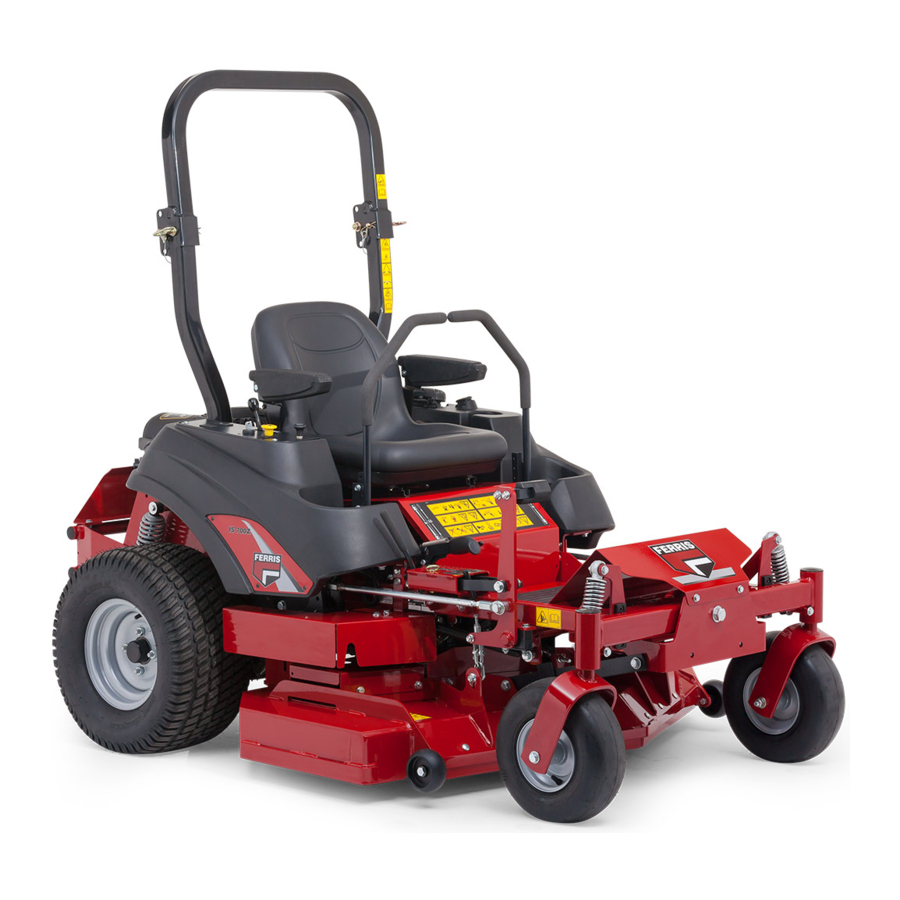
Ferris IS700Z Series Dealer Setup & Adjustment Instructions Manual
Zero-turn rider- 52"/62" mower deck
Hide thumbs
Also See for IS700Z Series
:
Operator's manual
(44 pages)
,
Operator's manual
(48 pages)
1
2
3
4
5
6
7
8
9
10
11
12
13
14
15
16
Table Of Contents
17
page
of
17
Go
/
17
Contents
Table of Contents
Bookmarks
Table of Contents
Quick Setup List
Setup Procedures
Connect the Battery Cables
Install the Seat
Check the Engine Oil Level
Check / Fill Transmission Oil Level
Check Tire Pressures
Deck Lift Rod Timing Adjustment
Deck Leveling Adjustment
Deck Lift Assist Springs
Lubricate the Front Casters
Checking/Adding Fuel
Starting the Engine - Carbureted Models
Functional Tests
Safety Interlock System
Adjustment Procedures
Seat Adjustment
Speed Balancing Adjustment
Ground Speed Control Lever Adjustment
Cutting Height Adjustment
Return-To-Neutral Adjustment
Neutral Lockout Adjustment
Purging the Air from the Hydraulic System
Rear Suspension Adjustment
Parking Brake Adjustment
Advertisement
Quick Links
1
Check the Engine Oil Level
2
Check / Fill Transmission Oil Level
3
Check Tire Pressures
4
Deck Leveling Adjustment
5
Adjustment Procedures
Download this manual
See also:
Operator's Manual
Table of
Contents
Previous
Page
Next
Page
1
2
3
4
5
Advertisement
Table of Contents
Need help?
Do you have a question about the IS700Z Series and is the answer not in the manual?
Ask a question
Questions and answers
Related Manuals for Ferris IS700Z Series
Lawn Mower Ferris IS700Z Series Operator's Manual
Zero-turn riding mower (48 pages)
Lawn Mower Ferris IS700Z series Operator's Manual
Zero-turn riding mower (44 pages)
Lawn Mower Ferris IS700ZB2752 Dealer Setup & Adjustment Instructions Manual
Zero-turn rider- 52"/62" mower deck (17 pages)
Lawn Mower Ferris IS700ZB2761 Dealer Setup & Adjustment Instructions Manual
Zero-turn rider- 52"/62" mower deck (17 pages)
Lawn Mower Ferris IS1500Z Series Operator's Manual
Zero-turn riding mower (52 pages)
Lawn Mower Ferris IS3000Z series Operator's Manual
Zero-turn riding mower (48 pages)
Lawn Mower Ferris IS5100Z Series Operator's Manual
Zero-turn riding mower (32 pages)
Lawn Mower Ferris IS2000Z Diesel Operator's Manual
Is2000z diesel series zero-turn riding mower (56 pages)
Lawn Mower Ferris IS2000Z Series Operator's Manual
Is2000z series zero-turn riding mower (48 pages)
Lawn Mower Ferris IS2100Z Series Operator's Manual
Is2100z series zero-turn riding mower (44 pages)
Lawn Mower Ferris IS500Z Series Operator's Manual
Is500z series zero-turn riding mower (52 pages)
Lawn Mower Ferris IS1500ZX Series Operator's Manual
Is1500z/ is1500zx series zero-turn riding mower (28 pages)
Lawn Mower Ferris IS2500Z Series Operator's Manual
Is2500z series 52/61" cut zero-turn riding mower (60 pages)
Lawn Mower Ferris IS3100Z Series Manual
(24 pages)
Lawn Mower Ferris IS600z series Operator's Manual
Zero-turn (44 pages)
Lawn Mower Ferris ISX800 Series Operator's Manual
Zero-turn riding mower (56 pages)
This manual is also suitable for:
Is700zb2752
Is700zb2761
Table of Contents
Save PDF
Print
Rename the bookmark
Delete bookmark?
Delete from my manuals?
Login
Sign In
OR
Sign in with Facebook
Sign in with Google
Upload manual
Upload from disk
Upload from URL


Need help?
Do you have a question about the IS700Z Series and is the answer not in the manual?
Questions and answers