Rinnai FC510N User Manual
Fan convector heaters
Hide thumbs
Also See for FC510N:
- Installation and operation manual (44 pages) ,
- Installation and operation manual (44 pages)
Advertisement
Table of Contents
- 1 Internal Components
- 2 Product Specifications
- 3 Sequence of Operation
- 4 Installation Instructions
- 5 Maintenance
- 6 Fault Codes
- 7 Wiring Diagram
- 8 Gas Valve Removal
- 9 Board Removal
- 10 Safety Circuit
- 11 Burner Assembly Removal
- 12 Fan Motor Removal
- Download this manual
See also:
Operation & Installation Manual
Advertisement
Table of Contents

Subscribe to Our Youtube Channel
Related Manuals for Rinnai FC510N


Summary of Contents for Rinnai FC510N
- Page 1 Rinnai Fan Convector Heaters Level III Training...
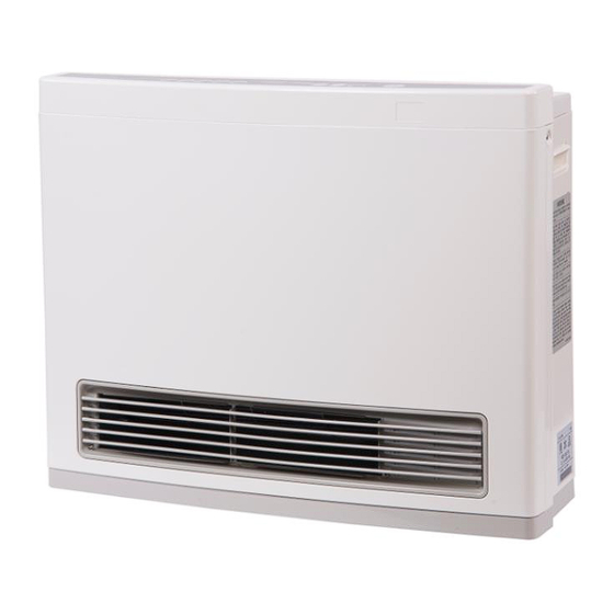
- Page 2 Fan Convector Heaters FC510 (RCE-391A) FC824 (RCE-691TA)
-
Page 3: Internal Components
Internal Components FC510 (RCE-391A) FC824 (RCE-691TA) -
Page 4: Product Specifications
Model Gas Type Gas Inlet Pressure HI/LO Inches W.C. Btu/hr. HIGH Btu/hr. LOW CFM HI/LO (Amps) (mm) FC510N 3.5 – 10.5 inches W.C 1.8 / 0.64 inches W.C. Natural Gas 10,000 5,500 67.8 Low (RCE-391AN) (89 – 267 mm W.C) (47 / 16.3 mm W.C.) - Page 5 Specifications Component/Clearance Specifications FC510 (RCE-391A) FC824 ( RCE-691TA) Gas Connection 1/2" Male NPT 1/2" Male NPT Gas Control Electronic Electronic Burners Ceramic Burner Ceramic Burner Temperature Control Electronic Thermostat Electronic Thermostat Ignition Sdystem Electronic Spark Ignition Electronic Spark Ignition Electrical Connection AC 120V, 60 Hz., 19 Watts AC 120V, 60 Hz., 29 Watts Weight...
- Page 6 Ledger Plate Explanation & Warranty • The letters “RCE” indicates this is a “Rinnai Convection Export” heater. • The numbers “510 & 824” indicate the model number of heater. • The letter “T” indicates duel timers on 824 model, no “T” indicates single timer on 510 model.
-
Page 7: Sequence Of Operation
Sequence of Operation 1. Convection fan starts, drawing air in through Thermocouple 1 Thermocouple 2 the back of the cabinet and across the heat exchanger / burner chamber and out into the space. The PCB verifies fan rotation. Gas Valve 2. - Page 8 Modulating Technology • Variable speed technology – Modulating gas and air based on the heat loss at that moment • With on/off single stage operation, gas usage • The Fan Convector modulating technology has the can be high due to alternating periods between ability to replace only the heat escaping the maximum flame and no flame at all structure by continuously operating at heating levels...
-
Page 9: Installation Instructions
Installation Instructions • Do not install this appliance above 2,000ft. • Do not block the warm air discharge. • Do not allow anyone to sleep directly in front of the appliance. • Do not insert items into the louvers. • Do not place clothing or other flammable material on or near the appliance •... - Page 10 • Rinnai suggests that a dedicated electrical circuit with a 120VAC, 60 hz, 10 amp power source be used. • The flow of combustion and ventilation air shall not be obstructed.
- Page 11 Code Limitations • Check Federal, State and/or local codes in your state before using vent-free products. Some areas of the country do not allow vent-free products. • International Fuel Gas Code Standard 620-6 under “Prohibited Use” states that; “One or more unvented room heaters shall not be used as a sole source of comfort heating in any dwelling unit”.
- Page 12 3. Annual Cleaning – Rinnai recommends that you blow out all compartments inside the unit. In addition, blow out the squirrel cage fan. Care should be taken when blowing out the fan. Keep the air nozzle at least twelve inches...
-
Page 13: Maintenance
Maintenance Cleaning Air Filters: Both air filters should be cleaned frequently during the heating season. 1. Unscrew the black cap (Phillips screw in the center of large filter) securing the air filter. Pull the filter up and away from the unit. 2. - Page 14 Error Codes & Troubleshooting...
-
Page 15: Fault Codes
Fault Codes An error code will flash on the unit’s display when a fault occurs. Refer to the list of error codes below for details on your unit’s fault code. All troubleshooting and repairs should be made by a licensed contractor. ERROR FAULT REMEDY... - Page 16 Fault Codes Check thermistor wiring for damage, loose or broken connections or wires. – Room Temperature Thermistor Measure resistance of thermistor – Replace Sensor – Room Temperature Thermistor Short circuit, replace thermistor – Check thermistor wiring for damage, loose or broken connections or wires –...
-
Page 17: Wiring Diagram
Wiring Diagram... - Page 18 Electrical Components Values Diagnostic Points Components Mark Wire Colors Value Pin # 3 & 4 Blue - Brown 10 - 12 VDC 2,000 - 5,000 Pulses/Min. Blue - Yellow (33 - 84 Hz) 1 & 3 Convection Fan Motor 2K - 10 KΩ 11 - 14 VDC Blue - Red 2 &...
- Page 19 Warnings There are a number of (live) tests that are required when fault finding this product. Extreme care should be used At all times to avoid contact with energized components inside the heater. Only trained and qualified service Technicians should attempt to repair this product. Before checking for resistance readings, disconnect the power Source to the unit and isolate the item from the circuit (unplug it).
- Page 20 Warnings Failure to correctly assemble the components according to the instructions contained within this presentation May result in a gas leak or explosion Inspect all gaskets/packings for signs of damage or corrosion. Gaskets/packings found to contain damage or that Appear questionable MUST BE REPLACED. Failure to replace damage or questionable gaskets may result in gas leak or explosion.
- Page 21 TC1 & TC2 Milli-volt Readings Procedure for measuring TC1 & TC2 Thermocouple Outputs Set voltage meter to read at least 35 milli-volts. Insert meter leads into the output test port holes on the rear of the unit, see below for proper test ports for each thermocouple. FC510 (RCE-391A) Thermocouple Output FC824 (RCE-691TA) Thermocouple Output TC1 (mV) Brown &...
-
Page 22: Gas Valve Removal
Gas Valve Removal Caution: Shut off gas and power supply to the unit before proceeding. 1. Disconnect gas piping to unit at the inlet gas connection shown below. 2. Disconnect the POV gas solenoid valve wiring harness, (red & white wires). 3. -
Page 23: Board Removal
P.C. Board Removal Caution: Disconnect the power and gas from the unit before proceeding. 1. Remove (1) screw from plastic P.C. board casing, front of unit 1/3 the way up the unit. 2. Lift up on the P.C. board casing and pull board out of unit. 3. -
Page 24: Safety Circuit
Safety Circuit Caution: Shut off gas and power supply to the unit before proceeding. 1. Burner sensor mounted on the left hand side of the burner assembly is designed to detect the burner temperature. If combustion conditions cause the burner temperature to drop below a predetermined temperature, the sensor will shut the unit off and flash an error code related to the fault. - Page 25 Igniter & Igniter Module Removal Caution: Shut off gas and power supply to the unit before proceeding. Igniter/electrode: 1. To remove the igniter unplug the black/green wires from the igniter. The green wire has a latch that has to be pushed in, in order to release the connector.
- Page 26 Burner Assembly Removal Next Seven Slides...
-
Page 27: Burner Assembly Removal
Burner Assembly Removal Caution: Shut off gas and power supply to the unit before proceeding. 1. Remove louver assembly by removing (3) screws as shown below. 2. Remove (2) screws from each side of the front cover, then pull cover away from unit. FC510 FC824... - Page 28 Burner Assembly Removal 1. Remove (4) screws on the FC510, (3) on the FC824 ,as shown below. 2. Unplug 15 pin connector from P.C. board. 3. Pull top panel away from unit.
- Page 29 Burner Assembly Removal Caution: Shut off gas and power supply to the unit before proceeding. 1. Disconnect the burner gas line from the gas control valve, (1) screw. Pull retainer clip off burner gas line. Pull gas line loose from the gas control valve. Verify O-ring is intact and in good condition. 2.
- Page 30 Burner Assembly Removal 1. Remove the (4) screws on the rear of the unit. 2. Remove (1) screw from left side of burner housing down next to floor base. 3. Slide the complete burner and fan assembly out of the unit.
- Page 31 Burner Assembly Removal 1. Remove the burner sensor on the left hand side of the burner housing, (3) screws. Pull the burner sensor retainer clip off the tab. 2. Remove the pilot assembly sensor and burner plate located on the right hand side of the burner housing, (4) screws.
- Page 32 Burner Assembly Removal 1. Remove (2) screws from bracket and pull loose from unit. 2. Remove (4) screws for the combustion box cover and remove cover. 3. Remove (2) screws from burner assembly cover and remove cover.
- Page 33 Burner Assembly Removal 1. Remove (3) screws holding burner assembly to heater housing. 2. Slide burner assembly out of the burner chamber from right side of unit. 3. Complete burner assembly after removed from unit. 4. Install new burner assembly in reverse order.
- Page 34 Cleaning Burner Assembly...
- Page 35 Cleaning Burner Caution: Shut off gas/power supply to the unit before proceeding. Wear safety glasses to preform task below. 1. Follow procedure for removing burner assembly, with exception to pulling the burner. The burner does not have to be removed to clean it. 2.
- Page 36 Cleaning ODS Pilot Orifice...
- Page 37 Cleaning ODS Pilot Orifice Caution: Shut off gas/power supply to the unit before proceeding. Wear safety glasses to preform task below. 1. Remove front cover on unit (4) screws. 2. Locate pilot and burner orifice on the right hand side of unit, center of burner housing. 3.
- Page 38 Fan Motor/Squirrel Cage Blower Removal Next Six Slides...
-
Page 39: Fan Motor Removal
Fan Motor Removal Caution: Shut off gas and power supply to the unit before proceeding. 1. Remove louver assembly by removing (3) screws as shown below. 2. Remove (2) screws from each side of the front cover, then pull cover away from unit. FC510 FC824... - Page 40 Fan Motor Removal 1. Remove (1) holding the igniter module in place and (1) screw holding ground wire in place. 2. Remove (2) screws holding partition board in place. 3. Unplug fan motor from P.C. board.
- Page 41 Fan Motor Removal 1. Remove (2) screws on the rear of unit. 2. Remove (2) screws on left side of burner housing. 3. Remove (2) screws on right side of burner housing. 4. Slide fan motor and housing assembly out of the unit.
- Page 42 Fan Motor Removal 1. Remove (4) screws holding fan motor to unit’s housing. 2. Loosen screw on fan motor shaft and pull fan motor loose from unit.
- Page 43 Squirrel Cage Blower Wheel Removal 1. Remove (2) screws on squirrel cage bearing housing assembly, left hand side of unit. Remove bearing housing. 2. Loosen screw on fan motor shaft, right side of unit. Slide blower wheel out of unit from left side of unit.
- Page 44 The End Fan Convection Heater Service Training...
Need help?
Do you have a question about the FC510N and is the answer not in the manual?
Questions and answers