Table of Contents
Advertisement
Quick Links
THIS MANUAL MUST BE READ IN ITS
ENTIRETY BEFORE OPERATING HEATER
Owners Operation and Installation Manual
WARNING: If the information in these instructions are not
followed exactly, a fire or explosion may result causing
property damage, personal injury or loss of life.
Do not store or use gasoline or other flammable vapors
and liquids in the vicinity of this or any other appliance.
• Do not try to light any appliance.
• Do not touch any electrical switch; do not use any phone in
your building.
• Immediately call your gas supplier from a neighbor's phone.
Follow the gas supplier's instructions.
• If you cannot reach your gas supplier, call the fire department.
Installation and service must be performed by a qualified
installer, service agency or the gas supplier.
This appliance is only for use with the type of gas indicated on
the rating plate.
This appliance is not convertible for use with other gases.
INSTALLER: MUST LEAVE THIS MANUAL WITH THE UNIT AFTER INSTALLATION
OWNER: RETAIN THIS MANUAL SAFELY, FOR FUTURE REFERENCE
HOME OWNER / INSTALLER
FOR YOUR SAFETY
FS35ETRN
FS35ETRLC
Gas Radiant Space Heater
WHAT TO DO IF YOU SMELL GAS
Advertisement
Table of Contents

Related Manuals for Rinnai FS35ETRN


Summary of Contents for Rinnai FS35ETRN
- Page 1 HOME OWNER / INSTALLER FOR YOUR SAFETY THIS MANUAL MUST BE READ IN ITS ENTIRETY BEFORE OPERATING HEATER FS35ETRN FS35ETRLC Gas Radiant Space Heater Owners Operation and Installation Manual WARNING: If the information in these instructions are not followed exactly, a fire or explosion may result causing property damage, personal injury or loss of life.
-
Page 2: Limited Warranty
Authorized Rinnai Distributor. Rinnai will not pay labor charges associated with the repair or replacement of the product or any part or component. All repair parts must be genuine Rinnai parts. All repairs or replacements must be performed by an individual or servicing company that has been authorized by Rinnai or its distributor. -
Page 3: Table Of Contents
Trouble shooting ......................20 Error codes ........................21 Exploded diagrams......................22 Spare parts list ....................... 24 Installation notes ......................26 Installation / commissioning checklist ................27 Installer details ....................... 27 CONTACTS 1-800-621-9419 America Corporation www.rinnai.us 103 International Drive Peachtree City Georgia 30269... -
Page 4: Specifications
SPECIFICATIONS Model: FS35ETRBN/US, FS35ETRSN/US (NG) United States FS35ETRBL/US, FS35ETRSL/US (Propane) United States Description: Freestanding radiant/convector, glass-fronted, ceramic log space heater with forced convection and natural draft flue system Gas Control: Electronic control valve Burners: Ember bed, flame and heat burner Warm Air Discharge: Top front louvres Flue:... -
Page 5: Important Points / Usage And Installation Musts
IMPORTANT POINTS / USAGE AND INSTALLATION MUSTS Unpack the heater and check for damage (DO NOT INSTALL DAMAGED HEATER). If the heater is damaged, contact your supplier for advice. Before installing the heater, check the label for the correct gas type (see rating plate, bottom right hand side of pillar). Refer to local gas authority for confirmation of the gas type if you are in doubt. - Page 6 of the control system and any gas control 24 The draft hood on the appliance should which has been under water. be installed in the same atmospheric pressure zone as the combustion air inlet 17 Adequate clearances for accessibility for to the appliance and shall be located so purposes of servicing and proper that the relief opening is accessible for...
-
Page 7: Technical Specifications
38 WARNING: DO NOT OPERATE COMPARTMENTS, BURNERS AND CIRCULATING AIR PASSAGEWAYS APPLIANCE WITH THE FRONT REMOVED, CRACKED OR BROKEN. OF THE APPLIANCE ARE KEPT CLEAN. REPLACEMENT OF THE GLASS SHOULD BE DONE BY A LICENSED 35 The glass window shall be replaced as OR QUALIFIED SERVICE PERSON. -
Page 8: For Your Safety
FOR YOUR SAFETY READ BEFORE OPERATING WARNING: If you do not follow these instructions exactly, a fire or explosion may result causing property damage, personal injury or loss of life. A This appliance is equipped with an a neighbor’s phone. Follow the gas ignition device which automatically suppliers instructions. -
Page 9: Control Panel Layout
CONTROL PANEL LAYOUT For your convenience the controls on your new Flame Fire are situated under the cover on the top right-hand side of the fire and are accessed by simply lifting the lid. All necessary adjustments to the operation of your fire can be made with these controls. OPERATION •... - Page 10 deactivate the LOCK press and hold the you have selected AM or PM as required, button for 3 seconds until the indicator a small indicator on the left hand side of goes off. the Digital Display indicates the AM/PM setting. During normal operation the LOCK may be activated and all controls, other than the Use the buttons again to set the minutes.
- Page 11 again when the power comes back on, but proceed to TIMER 2 - which is programmed in the same way - or three the time will be slow by the duration of the times to return to the clock display. This power failure.
- Page 12 • TO REPLACE REMOTE CONTROL ON BUTTON BATTERY Operates the unit manually. The battery is held in a clip that slides out the bottom of the remote control. The clip is removed by inserting a coin or similar OFF BUTTON into the recess in the back of the remote Stops unit control and sliding downwards.
-
Page 13: Location
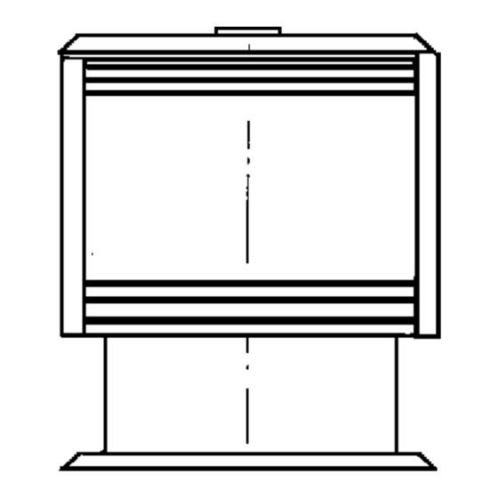
LOCATION When positioning the heater, the main points governing the location are: 5. The heater is not designed to be built 1. Flue connection and proper venting into bookcases or shelves or any 2. Warm air distribution. combustible opening. 3. Adequate air supply. 6. -
Page 14: Venting
VENTING Use only an approved B vent system horizontal at any stage. There must not be more than 2 bends in any system. • Position the heater. Any horizontal section of flue must be • Suspend a plumbline from the ceiling to less than 1/3 the length of vertical flue the centre of the flue socket. -
Page 15: Log Installation
LOG INSTALLATION The logset is packed inside the unit and the packaging must be removed prior to installing the logset in its correct position. • Open both side panels. • Remove fasteners on both sides of the top glass retainer. •... -
Page 16: Testing And Commissioning
TESTING AND COMMISSIONING • TESTING PROCEDURE It is the responsibility of the installer to check that under normal operating Turn gas supply on and plug the unit into conditions of the appliance, all flue the power supply. (Caution 115V) gases are exhausted to the outside atmosphere and that there is no spillage of combustion gases into the •... -
Page 17: Maintenance Instructions
MAINTENANCE INSTRUCTIONS IMPORTANT MAINTENANCE INSTRUCTIONS ANNUAL INSPECTION A heater should not be used if you suspect The unit should be inspected at least once there may be a problem, and a service a year by a qualified service technician agent must be called to investigate the including inspection of the flue system. - Page 18 The heater should be serviced annually only by an authorised person. • GLASS REPLACEMENT CLEANING. (May be performed by the owner) It is best to handle the glass with clean gloves to avoid smearing the glass with finger prints which might show after replacement.
-
Page 19: Pcb Layout
WIRING DIAGRAM Caution: Label all wires prior to disconnection when servicing controls. Wiring errors can cause improper dangerous operation. Verify proper operation after servicing. PCB LAYOUT... -
Page 20: Wiring Diagram-Ladder
WIRING DIAGRAM-LADDER TROUBLE SHOOTING SYMPTOM CAUSE SOLUTION No power present Ensure power cord is plugged in and turned on No gas present Ensure gas supply is turned on Burner will not light power cut Re-ignite after power is restored Air in gas pipe Purge air (installer) Ignition failure Repeat lighting procedure. -
Page 21: Error Codes
ERROR CODES • ERROR CODE MESSAGE The Flame Fire ETR has the ability to check its own operation continuously. If a fault occurs, an Error Message will flash on the Digital Display of the control panel. This assists with diagnosing the fault, and may enable you to overcome a problem without a service call. Please quote the code displayed when enquiring about service. -
Page 22: Exploded Diagrams
EXPLODED DIAGRAMS... -
Page 24: Spare Parts List
SPARE PARTS LIST ITEM NO. QTY. PART NO. DESCRIPTION 7992-1 FLUE SPIGOT ASSY FS NAT USA 7074 HEAT EXCHANGER FRONT ASSY 3+3H 7075 HEAT EXCHANGER REAR ASSY 3H 6624 BURNER EXCHANGER TRANSFER TUBE 6625 BURNER HEAT EXCHANGER BRACKET 7028-5 FLUE SPIGOT DRAUGHT DIVERTER 7926 COMB CHAMB ASSY FS ETR USA PAI 7022V... - Page 25 7508 HEATSHIELD RH FS35ETR 7509 HEATSHIELD LH FS35 7988V REAR PANEL FS35ETR VIPER USA BLACK 7988SP REAR PANEL FS35ETR SP USA SILVER 7472 AIR GUIDE LOWER FS35ETR 7062 HEATSHIELD LOWER RH FS ETR 7060 HEATSHIELD LOWER LH FS 7564 ELECTRODE SLEEVE 7482V TOP PANEL ASSY FS35ETR VIPER BLACK...
-
Page 26: Installation Notes
INSTALLATION NOTES... -
Page 27: Installation / Commissioning Checklist
INSTALLATION / COMMISSIONING CHECKLIST 1. Was a fireplace inspection carried out? (i.e. clearances, combustibles etc.) 2. Was a manufactured flue system installed? 3. Has specified gas pressure been set? 4. Are decorative logs located correctly on pins? 5. Have ember granules been placed and free of dust and powder? 6.Has the appliance been test fired for correct operation (All burners light without delay) - Page 28 Part Number 7917B...
Need help?
Do you have a question about the FS35ETRN and is the answer not in the manual?
Questions and answers