
Related Manuals for Meyer Sound MDM-832


Summary of Contents for Meyer Sound MDM-832
- Page 1 OPERATING INSTRUCTIONS POWER MDM-832 Distribution Module Keep these important operating instructions. Check www.meyersound.com for updates.
- Page 2 Meyer Sound. Compass, Galileo, Callisto, Meyer Sound, and the Meyer Sound wave logo are registered trade- marks of Meyer Sound Laboratories Inc. (Reg. U.S. Pat. & Tm. Off.). All third-party trademarks mentioned herein are the property of their...
-
Page 3: Table Of Contents
AC Power Distribution MDM-832 Voltage Requirements MDM-832 Current Requirements Powering On the MDM-832 Electrical Safety Guidelines Chapter 3: MDM-832 Front and Rear Panels MDM-832 Front Panel MDM-832 Rear Panel Chapter 4: Powering Loudspeakers with the MDM-832 Cable Configurations RMS Network... - Page 4 CONTENTS...
-
Page 5: Chapter 1: Introduction
MDM-832 DISTRIBUTION MODULE Make sure to read these instructions in their entirety before The MDM-832 distribution module routes up to eight chan- configuring an MDM-832. In particular, pay close attention nels of AC power, balanced audio, and RMS™ to multiple to material related to safety issues. -
Page 6: Supported Loudspeakers
Product Safety and Declaration of Conformity information is also available at www.meyersound.com. SUPPORTED LOUDSPEAKERS The MDM-832 is an ideal solution for power and signal dis- tribution to small- and medium-sized AC-powered Meyer Sound loudspeakers with auto-ranging input voltage selec- tion. -
Page 7: Chapter 2: Mdm-832 Power Requirements
AC POWER DISTRIBUTION Ground All components in an audio system (self-powered loud- Figure 1: 120 V AC, 3-Phase Wye System (Two Lines to Each MDM-832) speakers, mixing consoles, and processors) must be prop- erly connected to an AC power distribution system, ensuring... -
Page 8: Mdm-832 Voltage Requirements
It is also used for calcu- neutral line to the AC Input of the MDM-832, as the lating the peak voltage drop in long AC cable runs resulting voltage would be higher than the allowable... -
Page 9: Electrical Safety Guidelines
MDM-832 OPERATING INSTRUCTIONS ELECTRICAL SAFETY GUIDELINES Make sure to observe the following important electrical and safety guidelines. ■ The Meyer Sound MDM-832 requires a grounded outlet. Always use a grounded outlet and plug. Ground Ground ■ Do not use a ground-lifting adapter or cut the AC cable ground pin. - Page 10 CHAPTER 2: MDM-832 POWER REQUIREMENTS...
-
Page 11: Chapter 3: Mdm-832 Front And Rear Panels
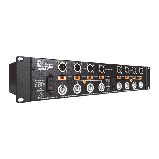
Outputs 1–4; the other breaker switch corresponds to AC audio inputs on the rear panel of the MDM-832. Audio out- Outputs 5–8. puts are available as either XLR 5-pin male connectors or Each set of four MDM-832 outputs is capable of powering XLR 3-pin male connectors. -
Page 12: Mdm-832 Rear Panel
Ground world. Make sure to use the correct power connector for the powerCON 20 AC Looping Output Connector AC power in your area. The MDM-832 operates as intended within an AC voltage range of 100–240 V at 50–60 Hz. - Page 13 The following examples illustrate several common routing tem be properly grounded. For information about supplying applications for the Link switches. power to the MDM-832, see Chapter 2, “MDM-832 Power Requirements.” Routing One Input to Eight Outputs To route one input to eight channel outputs: Audio Inputs ■...
- Page 14 CHAPTER 3: MDM-832 FRONT AND REAR PANELS Routing Two Inputs to Four Outputs Each ■ 2 channel outputs, 5 kOhms input impedance To route two inputs to four channel outputs each: ■ 4 channel outputs, 2500 ohms input impedance ■...
-
Page 15: Chapter 4: Powering Loudspeakers With The Mdm-832
CHAPTER 4: POWERING LOUDSPEAKERS WITH THE MDM-832 NOTE: For information on cable requirements 9. Switch both breakers on the MDM-832 front panel to the for your loudspeaker, refer to its operating ON position. Monitor the front-panel LEDs to verify that instructions. -
Page 16: Cable Configurations
Composite cables carry AC power, balanced audio, and which in turn use loop outputs to distributed AC power, bal- RMS through a single cable. Channels of the MDM-832 are anced audio, and RMS to additional loudspeakers. connected to loudspeakers, which in turn use loop outputs to distributed AC power, balanced audio, and RMS to addi- tional loudspeakers. -
Page 17: Rms Network
RMS network ports of the sec- ond module. To connect the MDM-832 to RMServer, connect an RMS cable to one of the RMS network ports of the MDM-832, then connect the other end to one of the FT-10 ports of RMServer. - Page 18 CHAPTER 4: POWERING LOUDSPEAKERS WITH THE MDM-832...
-
Page 19: Chapter 5: Mdm-832 System Examples
CHAPTER 5: MDM-832 SYSTEM EXAMPLES NOTE: Separate power and signal connections are shown in all system examples. To simplify cable runs, use composite cable to carry both power and signal to each loudspeaker. See Appendix A, “Composite Cable.” (6) MJF-208 AND (2) MJF-212A (115 V, 208 V, OR 230 V) - Page 20 CHAPTER 5: MDM-832 SYSTEM EXAMPLES List of Components Table 1: (6) MJF-208 and (2) MJF-212A Part Number Description Count 09.245.001.01 (UL) or 09.245.001.03 (CE) MDM-832 Distribution Module (5-pin) Composite cable, 30 m 27.033.111.01 or compatible third-party com- posite cable Composite cable, 1.5 m 466.047...
-
Page 21: Leopard And (4) 900-Lfc (208 V, Or 230 V)
MDM-832 OPERATING INSTRUCTIONS (12) LEOPARD AND (4) 900-LFC (208 V, OR 230 V) 1 2 3 4 10 11 12 13 Legend Balanced Audio and RMS Power Galileo Callisto Channels Galileo Callisto 616 LEOPARD 900-LFC... - Page 22 CHAPTER 5: MDM-832 SYSTEM EXAMPLES List of Components Table 2: (12) LEOPARD and (4) 900-LFC Part Number Description Count 09.245.001.01 (UL) or 09.245.001.03 (CE) MDM-832 Distribution Module (5-pin) Composite cable, 30 m 27.033.111.01 or compatible third-party com- Composite cable, 1.5 m...
-
Page 23: Upa-1P (115 V, 208 V, 230 V)
MDM-832 OPERATING INSTRUCTIONS (8) UPA-1P (115 V, 208 V, 230 V) Legend Balanced Audio Power Galileo Callisto Channels Galileo Callisto 616 UPA-1P... - Page 24 CHAPTER 5: MDM-832 SYSTEM EXAMPLES List of Components Table 3: (8) UPA-1P Part Number Description Count 09.245.001.02 (UL) or 09.245.001.04 (CE) MDM-832 Distribution Module (3-pin) Composite cable, 30 m 27.033.111.01 or compatible third-party com- posite cable Composite cable, 1.5 m 466.047...
-
Page 25: Appendix A: Composite Cable
ASSEMBLING COMPOSITE CABLES When connecting loudspeakers to the MDM-832 with composite cable, you must terminate each end of the cable with the correct connectors to supply AC power, balanced audio, and RMS to the loudspeaker. XLR 5-pin connectors can be used with composite cables to carry RMS and balanced audio through a single connector, provided the MDM-832 and connected loudspeakers are configured with XLR 5-pin connectors. - Page 26 Silver CAUTION: When wiring cables for the MDM-832 AC outputs, it is extremely important that each pin in the con- nector be wired correctly, to avoid damage to the loudspeaker. In addition, make sure that audio pins are wired correctly; polarity reversals for audio signals affect system performance. RMS connectors are polarity insensitive.
- Page 27 When wiring AC power cables and distribution systems, it is important to preserve AC line polarity and connect the ground on both ends of the cable. CAUTION: The MDM-832 requires a grounded connection. Always use a grounded outlet and plug.
- Page 28 APPENDIX A: COMPOSITE CABLE...
-
Page 29: Appendix B: Orienting The Mdm-832 Rackmount Brackets
4. Secure the MDM-832 to the rack rails with four 10-32 truss head screws. ■ To mount the module with the rear panel at the front of... - Page 30 APPENDIX B: ORIENTING THE MDM-832 RACKMOUNT BRACKETS...
-
Page 31: Appendix C: Mdm-832 Specifications
Two LED indicators for AC voltage presence AC Outputs Eight powerCON 20 connectors Note: Connect only to Meyer Sound self-powered loudspeakers with auto-ranging input voltage selection. Circuit Breakers Two 15 A breaker switches for enabling AC outputs 1–4 and 5–8... - Page 32 APPENDIX C: MDM-832 SPECIFICATIONS MDM-832 DIMENSIONS 19.00 [483 mm] 3.50 [89 mm] Front view (3-pin output connectors) Front view (5-pin output connectors) 17.00 [432 mm] 8.50 [216 mm] Top view (recessed position) Top view (flush position) MDM-832 Dimensions...
- Page 33 MDM-832 OPERATING INSTRUCTIONS...
- Page 36 Meyer Sound Laboratories Inc. © 2016 2832 San Pablo Avenue Meyer Sound. All rights reserved. Berkeley, CA 94702 MDM-832 Operating Instructions +1 510 486.1166 PN 05.245.005.02 A www.meyersound.com...
Need help?
Do you have a question about the MDM-832 and is the answer not in the manual?
Questions and answers