Table of Contents
Advertisement
Quick Links
Advertisement
Table of Contents

Related Manuals for Planet VF-402-KIT


Summary of Contents for Planet VF-402-KIT
- Page 1 4-Channel Video over Fiber Bundle Kit VF-402-KIT Manual...
- Page 2 Copyright Copyright © 2013 by PLANET Technology Corp. All rights reserved. No part of this publication may be reproduced, transmitted, transcribed, stored in a retrieval system, or translated into any language or computer language, in any form or by any means, electronic, mechanical, magnetic, optical, chemical, manual or otherwise, without the prior written permission of PLANET.
- Page 3 FCC Caution To assure continued compliance. (example-use only shielded interface cables when connecting to computer or peripheral devices). Any changes or modifications not expressly approved by the party responsible for compliance could void the user’s authority to operate the device. This device complies with Part 15 of the FCC Rules.
- Page 4 Do not dispose of WEEE as unsorted municipal waste and have to collect such WEEE separately. Revision User’s Manual for 4-Channel Video over Fiber Bundle Kit (VF-402-T + VF-402-R) Model: VF-402-KIT Rev: 1.1 (January 2013) Part No. EM-VF-402-KIT...
-
Page 5: Table Of Contents
Table of Contents Chapter 1. Product Introduction ................ 6 1.1 Package Contents ................6 1.2 Product Description ................6 1.3 Application ..................9 1.4 Product Features ................10 1.5 Product Specification ................10 1.6 Dimension of Installing ...............12 Chapter 2. Hardware Description ..............13 2.1 Panel Overview ..................13 Chapter 3. -
Page 6: Chapter 1. Product Introduction
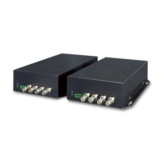
IP-Based surveillance gradually. To help the analog camera deployment in long distances to provide high video transmission quality and reliable signal, PLANET develops the Video over Fiber media converter which successfully integrates the video signal and fiber optic transmission in a compact size mini box. - Page 7 Fiber Optic Communication for VIDEO and SERIAL DATA This Video over Fiber Converter kit consists of a Video Transmitter and a Video Receiver: VF-402-T: 4-channel Video over Fiber Transmitter VF-402-R: 4-channel Video over Fiber Receiver Fiber-optic transmission system This Video over Fiber Converter kit consists of a Video Transmitter, VF-402-T, and a Video Receiver, VF-402-R (Figure 1).
- Page 8 Industrial monitoring systems Industrial level super wide temperature range -25 to 75 Degree C, applicable to lots kinds of environment, also support hot plug, VF-402-KIT, 4 channel video adopts advanced international no compression full digital error correction and gigabit fiber optical transmission technology to fulfill VF-402-KIT without distortion from long- distance in high quality through one fiber.
-
Page 9: Application
/ single fiber link. It is an ideal cost-effective solution for surveillance system that requires high display quality and high performance signal transmission over long distances. The VF-402-KIT can be installed easily and plug and play; that means the operator does not need to configure the pair of the video over fiber transmission in advance. -
Page 10: Product Features
Typical Applications Intelligent Transportation Systems (ITS) Toll Collection Traffic Surveillance Air Traffic Management (ATM) Rail Signaling Perimeter Alarms and Area Monitors Telemedicine and Teleconference Industrial Surveillance Intelligent Building CCTV network 1.4 Product Features 20km long distance data transmission Fiber optic transmission of four video signals on one fiber with RS485 data signals which may be one way with the video or optionally duplex Status indication for power supply, optical signal and video High-Speed synchronous digital transmission technology... - Page 11 Video Digital Bit Width 8/10 bit Differential Gain (DG) <1.3% (Typical Value) Differential Phase (DP) <1.3° (Typical Value) SNR Weighted >63dB (Typical Value) Data Interface Data Channel 4 channel Physical Protocol RS-485 Operation Mode Simplex Data Connector 4 Pin terminal block with screw clamps Data Rate DC-150Kbps Data Distance...
-
Page 12: Dimension Of Installing
Environment Temperature: -25 ~ 75 Degree C Operating Relative Humidity: 0 ~ 95% (non-condensing) Temperature: -40 ~ 85 Degree C Storage Relative Humidity: 5 ~ 95% (non-condensing) 1.6 Dimension of Installing 110mm 47mm POWER 110mm 47mm 102mm 27mm 122mm 133mm 14mm 174mm... -
Page 13: Chapter 2. Hardware Description
Chapter 2. Hardware Description 2.1 Panel Overview ■ Front Panel: ■ Video interface Item Description VIDEO/V1…V4 Video input interface ■ Fiber interface Item Description Fiber interface (Warning: In case of damage to eyesight, Do not FIBER/OPT look directly into interface on electrify state). For Optical transceiver B type, this interface is empty, wiring out from the rear panel. - Page 14 ■ Rear Panel: There is a power interface and power indicator on the rear panel, both PWR is ON when power on. FIBER is fiber interface; the description of each is as follows: POWER ■ Power Supply Power supply… Input AC 90~264V, 50~60HZ Output 5V / 2A...
-
Page 15: Chapter 3. Installation
Chapter 3. Installation This section describes how to install your VF-402-KIT Video over Fiber and make connections to the converter. Please read the following topics and perform the procedures in the order being presented. The hardware installation of PLANET VF-402-KIT Video over Fiber Converter do not need software configuration. To install your VF-402-KIT on a desktop or shelf, simply complete the following steps. -
Page 16: Order For Installation
(7) The relation of the video of optical transmitter and optical receiver is one-to-one, which means V1~V4 of optical transmitter is one-to-one to V1~V4 of optical receiver. 3.3 Order for installation (1) Connect the interface of optical transmitter with camera or speed dome. Then connect the optical fiber and the power supply. -
Page 17: Stand-Alone Installation
3.4 Stand-alone Installation To install a VF-402-T / VF-402-R stand-alone, on a desktop or shelf, simply complete the following steps: Step 1: Turn off the power of the analog camera / monitor to which the VF-402-T / VF-402-R will be attached. Step 2: VF-402-T (Transmitter): Connect coaxial cable from analog camera to Video BNC port of the VF-402-T. -
Page 18: Rack Mounting And Wall Mount
3.5 Rack Mounting and Wall mount Rack Mount: Check device is tightly on the track Wall Mount: Easier to put device on the wall with screws... -
Page 19: Appendix A: Precautions
Appendix A: Precautions (1) Insert fiber rightly into the fiber interface; avoid breaking off fiber because of applying too much force. The rolling diameter shall not be too short (not less than 20CM). (2) Fasten the retaining screw after connecting terminal blocks. (3) Do not remove the dust cap before installation, in order to avoid dirt and other things getting into port, increasing the loss of optical signal and affecting the transmission quality. -
Page 20: Appendix B: Troubleshooting
Appendix B: Troubleshooting Question Answer or Resolution Power supply indicator Check if the power plug is loose and the fuse wire of is OFF chassis. Check if optical output power is normal and in the Abnormal video data range of receiving sensitivity. Incorrect video input synchronization, check if the grounding electrical level is equal, especially the Irregular horizontal...
Need help?
Do you have a question about the VF-402-KIT and is the answer not in the manual?
Questions and answers