Makita DBN500 Technical Information
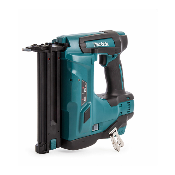
Cordless brad nailer 50mm (2")
Hide thumbs
Also See for DBN500:
- User manual ,
- Instruction manual (73 pages) ,
- Instruction manual (64 pages)
Advertisement
Quick Links
Download this manual
See also:
Instruction Manual
T
ECHNICAL INFORMATION
Models No.
Description
C
ONCEPT AND MAIN APPLICATIONS
DBN500 is cordless brad nailer powered by 18V Li-ion battery.
Compressed air generated by piston work with DC motor pushes down Driver to
shoot Brad nails. The mechanism provides less reaction force and "air nailer like"
shot feeling to the operator.
Other features are as follows:
• Higher durability than competitors' models
• Easy-to-see slim nose tip
• Rocker switch to select Sequential mode / Bump fire mode
S
pecification
Voltage: V
Cell
Battery
Capacity: Ah
Energy capacity: Wh
Charging time (approx.): min.
Max output (W)
Type
Length: mm (
Nail
Nail gauge
Nails per strip
Magazine capacity (pcs)
Shot quantity on a single full battery charge
Quick response (pcs/sec.)
Driving depth adjustment
Anti-dry-fire mechanism
Change of Bump fire mode and sequential mode
Operation
mode
2 mode pattern
LED job light
Weight according to EPTA-Procedure 01/2003: kg (lbs)
*3 One nail is fired first by pushing Contact arm against workpiece, then by pulling Trigger with the Contact arm
kept pushed; nail cannot be fired when the steps are reversed. Another one can be fired by releasing Trigger,
then by repeating the steps; however, cannot be fired if Trigger is not released before repetition of the steps.
*4 Nail is fired first by pulling Trigger then by bumping Contact arm against workpiece with Trigger kept pulled.
As long as Trigger is kept pulled, nails can be fired one after the other continuously every time when Contact arm
is bumped against workpiece.
*5 Nail is fired first by pushing Contact arm against workpiece then by pulling Trigger with Contact arm kept pushed.
Another nail can be fired by releasing then re-pulling Trigger even if Contact arm is kept pushed;
another nail cannot be fired if Trigger is not released.
*6 2.9kg (5.5lbs) without Battery
S
tandard equipment
Battery .................. 1 or 2*
Charger ................. 1*
8
Battery cover......... 1*
9
Safety goggles ...... 1
*8 Battery and charger are not supplied with "Z" model
*9 Supplied with the same quantity of extra Battery
Note: The standard equipment may vary by country
or model variation.
DBN500
Cordless brad nailer 50mm (2")
"
)
Nose adapter ................. 1
8
Hex wrench 3 ................ 1
Plastic carrying case ...... 1
(for some countries only)
H
Length (L)
Width (W)
Height (H)
*1
With Battery BL1830
*2
103mm (4-16") when using Hook
18
Li-ion
1.5, 2.0, 3.0, 4.0, 5.0
24, 27, 54, 72, 90
15, 24, 22, 36, 45 with DC18RC
460
Finish
15, 20, 25, 30, 32, 35, 38, 40, 45, 50
(5/8, 3/4, 1, 1-3/16, 1-1/4, 1-3/8, 1-1/2, 1-5/8, 1-3/4, 2)
18Ga
100
110
1,000*
2
Yes (Tool-less)
Yes
Rocker switch
Auto change mode between
*
Sequential
3
Bump fire
Yes
3.3 (7.3), 3.3 (7.3), 3.5 (7.7), 3.5 (7.7), 3.5 (7.7) *
O
ptional accessories
Finish nails
Fast charger DC18RC
Battery BL1815
Charger DC18SD
Battery BL1815N
Charger DC24SC
Battery BL1820
Four port multi charger DC18SF
Battery BL1830
Automotive charger DC18SE
Battery BL1840
Battery BL1850
OFFICIAL USE
for ASC & Sales Shop
PRODUCT
P 1/ 24
W
L
Dimensions: mm (")
294 (11-5/8)*
1
97 (3-13/16)*
2
318 (12-1/2)
1
*
*
and single fire
4
5
6
Advertisement

Subscribe to Our Youtube Channel
Related Manuals for Makita DBN500


Summary of Contents for Makita DBN500
- Page 1 Cordless brad nailer 50mm (2") ONCEPT AND MAIN APPLICATIONS DBN500 is cordless brad nailer powered by 18V Li-ion battery. Compressed air generated by piston work with DC motor pushes down Driver to shoot Brad nails. The mechanism provides less reaction force and “air nailer like”...
-
Page 2: Necessary Repairing Tools
P 2/ 24 epair CAUTION: Repair the machine in accordance with “Instruction manual” or “Safety instructions”. [1] NECESSARY REPAIRING TOOLS Code No. Description Use for 1R014 1/4” Hex shank bit for M4 disassembling / assembling M4 Hex socket head bolt 1R015 1/4”... - Page 3 P 3/ 24 epair [3] ADHESIVE APPLICATION AND TIGHTENING TORQUE Apply adhesive to the bolts designated with black arrows. See Fig. 2 for the item Nos. and descriptions that should be glued. Note: Their bolts are thread-locker type. First, use L-shaped hex wrench to unscrew them for repair. After that, remove them using Cordless impact driver with 1R014/ 1R015.
- Page 4 P 4/ 24 epair [3] ADHESIVE APPLICATION AND TIGHTENING TORQUE (cont.) Tightening torque Fastening for Description Adhesive to be applied (N.m.) Driver cylinder and Cylinder end M4x16 Hex socket head bolt 2.7 to 4.2 Plate A and Set plate M4x6 Hex socket head bolt 2.7 to 4.2 Arm and Center plate M4x6 Hex socket head bolt...
- Page 5 P 5/ 24 epair [4] DISASSEMBLY/ ASSEMBLY [4]-1. Magazine section DISASSEMBLING (1) Remove Magazine section, and then separate Slide door from Magazine. (Fig. 3) Fig. 3 1. Remove two M4x12 Pan head screws. 2. Remove M4x6 Hex socket head bolt and two M5x20 Hex socket head bolts (Thread-locker type).
- Page 6 P 6/ 24 epair [4] DISASSEMBLY/ ASSEMBLY [4]-1. Magazine section (cont.) DISASSEMBLING (2) Remove Pusher from Slide door. (Fig. 4) Fig. 4 1. Pull Pusher toward Set plate installation side fully, and lift up the center hook of Pusher slightly and carefully without detaching the side hooks of Pusher from Sleeves.
- Page 7 P 7/ 24 epair [4] DISASSEMBLY/ ASSEMBLY [4]-1. Magazine section (cont.) DISASSEMBLING (3) Remove Lock lever from Slide door. (Fig. 5) Fig. 5 1. Push out Pin 3 with 1R268 and a metal hammer. 2. Disassemble Lock lever section. Metal hammer Compression spring 7 1R268...
- Page 8 P 8/ 24 epair [4] DISASSEMBLY/ ASSEMBLY [4]-1. Magazine section (cont.) ASSEMBLING Assemble Pusher section to Slide door. (Fig. 8) Fig. 8 1. Insert two Compression springs 6 into the grooves of Slide door. Slide door 2. Move Pusher so that the center hook of Pusher comes over the groove end of Slide door.
- Page 9 P 9/ 24 epair [4] DISASSEMBLY/ ASSEMBLY [4]-2. Armature DISASSEMBLING Remove Housing R, and then separate Switch unit. (Fig. 9) Fig. 9 1. Remove two M4x12 Pan head screws, ten Bind PT3x36 Tapping screws and Housing R. Bind PT3x16 Tapping screw (10 pcs.) Housing R M4x12 Pan head...
- Page 10 P 10/ 24 epair [4] DISASSEMBLY/ ASSEMBLY [4]-2. Armature (cont.) DISASSEMBLING See Fig. 10 for removing Armature section. Fig. 10 1. Remove an module (Motor housing, Main cylinder, etc.) 2. Pull out Motor housing set from Gear assembly. from Housing L Main cylinder Motor housing Gear assembly...
- Page 11 P 11/ 24 epair [4] DISASSEMBLY/ ASSEMBLY [4]-2. Armature (cont.) DISASSEMBLING See Fig. 11 for the disassembly of Armature section. Fig. 11 1. Remove the end of Torsion springs of Brush holder complete from Carbon brushes and hook them in the notches of metal brush holders, then disconnect Carbon brushes from Commutator by pulling them in the direction of the black arrows.
- Page 12 P 12/ 24 epair [4] DISASSEMBLY/ ASSEMBLY [4]-2. Armature (cont.) ASSEMBLING See Fig. 12 for the assembly of Armature, Yoke unit and Motor housing set. Fig. 12 1. Face the notch of Yoke unit toward Armature gear end side Fan (the component and assemble Armature to Yoke unit.
- Page 13 P 13/ 24 epair [4] DISASSEMBLY/ ASSEMBLY [4]-3. Gear assembly DISASSEMBLING Fig. 13 After removing Motor housing set from Gear assembly as mentioned in page 9, M4x12 Hex socket remove four M4x12 Hex socket head bolts and Gear assembly from Crank case. head bolt (4 pcs.) (Fig.
- Page 14 P 14/ 24 epair [4] DISASSEMBLY/ ASSEMBLY [4]-4. Switch base, Crank, Main cylinder, Cylinder end DISASSEMBLING (1) Remove the module of Driver guide and Magazine, and then remove Motor section and Gear assembly from the module. (Refer to Pages 9, 10 and 13.) (2) Remove Switch base section.
- Page 15 P 15/ 24 epair [4] DISASSEMBLY/ ASSEMBLY [4]-4. Switch base, Crank, Main cylinder, Cylinder end (cont.) DISASSEMBLING Remove an module of Sub arm and Link arm A, and then separate Driver cylinder section, Crank section, Main cylinder section and Cylinder end section. (Fig. 17) Fig.
- Page 16 P 16/ 24 epair [4] DISASSEMBLY/ ASSEMBLY [4]-4. Switch base, Crank, Main cylinder, Cylinder end (cont.) DISASSEMBLING (4) Remove Housing R, and then separate Switch unit. (Fig. 18) Fig. 18 1. Remove four M4x16 Hex socket head screws, 2. Remove M4x8 Pan head screw and Magnet base complete and then separate Main cylinder section from from Crank, and then separate Connecting rod with Piston A Cylinder end section.
- Page 17 P 17/ 24 epair [4] DISASSEMBLY/ ASSEMBLY [4]-5. Valve, Crank, Driver complete, Cushion DISASSEMBLING (1) Remove Motor housing set from Gear assembly. Refer to pages 10 and 11. (2) Remove Driver complete as drawn in Fig. 19. Fig. 19 1. Remove M4x6 Hex socket head bolt, and then separate Arm from Center plate.
- Page 18 P 18/ 24 epair [4] DISASSEMBLY/ ASSEMBLY [4]-6. Adjuster DISASSEMBLING Following the steps mentioned in Fig. 16 of page 14, remove Switch base. And then, remove Adjuster as drawn in Fig. 20. Fig. 20 1. Remove Urethane ring 4, and then 2.
- Page 19 P 19/ 24 epair [4] DISASSEMBLY/ ASSEMBLY Fig. 22 [4]-7. Sub arm, Link arm A Pin 4 Ball bearing 604ZZ Slider DISASSEMBLING Compression Link arm A Remove M4x10 Hex socket head bolt and Plate B, and then separate spring 3 M4x16 Hex socket head bolt on Flat washer 4.
- Page 20 P 20/ 24 epair [4] DISASSEMBLY/ ASSEMBLY [4]-7. Sub arm, Link arm A (cont.) ASSEMBLING (5) Assemble Switch base section and then set Compression spring 11, Rear cushion, Top cap and two M4x10 Hex socket head bolts as drawn in Fig. 26. Fig.
- Page 21 P 21/ 24 epair [4] DISASSEMBLY/ ASSEMBLY [4]-8. Check of Air leakage ASSEMBLING See Fig. 28. Fig. 28 Fill the hole of Driver cylinder for air path using your finger in condition that Driver complete is set in place, and check that you cannot push and pull Driver assembly by hand. If you can move Driver assembly, air leakage occurs somewhere.
-
Page 22: Circuit Diagram
P 22/ 24 ircuit diagram Fig. D-1 Tape Printed circuit board for LED Black Printed circuit board for crank Switch unit angle sensor Connectors Black Brush holder complete Switch Blue Blue Sleeve Sleeve Controller Insulated connector 5.5-SD Black White Yellow Blue Black Terminal... -
Page 23: Wiring Diagram
P 23/ 24 iring diagram Fig. D-2 Wiring view under Switch unit for Trigger Switch unit for Contact arm Lead wires of Switch unit for Contact arm must be routed Ribs J between Ribs J and Rib K. Rib K Ribs H Switch unit for trigger Lead wires from two... - Page 24 P 24/ 24 iring diagram Fig. D-3 Wiring around Switch base section Fix Lead wires of Switch unit for (Contact arm) Fix Lead wires of Switch unit (for Contact arm) into these lead wire holders. into these lead wire holders individually. Switch unit for Contact arm Lead wire holder A...
Need help?
Do you have a question about the DBN500 and is the answer not in the manual?
Questions and answers