Table of Contents
Advertisement
Quick Links
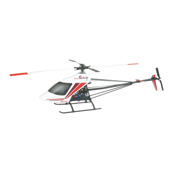
elektro
Skalar
Model helicopter
Order No. 4475 Kit
Order No. 4476 Mechanics Kit
Warning!
The contents of this kit can be assembled to produce a working RC helicopter, but the
model is by no means a harmless plaything. It is a complex flying machine, and if
assembled incorrectly or handled incompetently or carelessly it can cause serious injury
to persons and damage to property.
You alone are responsible for completing the model correctly and operating it safely. The
kit also includes two further information sheets - SHW 3 and SHW 7 - which include
safety notes. They are an essential part of these instructions.
GRAUPNER GmbH & Co. KG D-73230 KIRCHHEIM/TECK GERMANY
No liability for modifications, errors and printing errors.
ID# 57057
12/06
Advertisement
Table of Contents

Related Manuals for GRAUPNER Skalar


Summary of Contents for GRAUPNER Skalar
- Page 1 - SHW 3 and SHW 7 - which include safety notes. They are an essential part of these instructions. GRAUPNER GmbH & Co. KG D-73230 KIRCHHEIM/TECK GERMANY No liability for modifications, errors and printing errors.
- Page 2 1160 to 1365 mm. The elektro Skalar mechanics kit, Order No. 4476, is designed to be installed in any suitable fuselage in the Graupner/Heim system. It contains the main chassis including main rotor head, plus tail rotor and tail rotor gearbox, but excludes the tail boom, skid landing gear, main rotor blades and cabin.
-
Page 3: Warning Notes
Skalar elektro Warning notes • The contents of this kit can be assembled to produce a working helicopter, but the model is by no means a harmless plaything. If assembled incorrectly or handled incompetently or carelessly it can cause serious injury to persons and damage to property. - Page 4 Liability exclusion / Compensation As manufacturers, we at GRAUPNER are not in a position to influence the way you build and set up the model, nor install, operate and maintain the radio control system components.
-
Page 5: Table Of Contents
Skalar elektro Contents • Foreword ....…......• Warning notes ........• Accessories, additional items required ....• 1. Assembling the main mechanics ..... • 2. Installing the radio control system ..... P.19 • 3. Assembling the main rotor head ...... - Page 6 Skalar elektro Accessories Recommended motors and accessories for the elektro Skalar Motor Speed controller Batteries COMPACT 555 18,5V COMPACT CONTROL 80 1 Pcs. LiPo 5/3400, Order No.7648.5 or LiPo 5/4800, Order No.7658.5 Order No. 7726 HELI 2 Pcs. LiPo 3/3400, Order No.7648.3 or LiPo 3/4800, Order No. 7658.3 Order No.
-
Page 7: Assembling The Main Mechanics
In the Graupner/Heim system the fits between shafts and ballraces are maintained on the tight side, in order to avoid the problems described above. However, manufacturing tolerances are inevitable, and occasionally the result is too tight a fit, i.e. - Page 8 Skalar elektro 1.1 Assembling the tail rotor drive unit (bag UM-1A The shaft of the quick-release coupling 4618.57 must not exhibit any axial play in the bearings 4618.6. If the shaft is not a tight enough fit in the bearings, glue it in the ballraces using bearing retainer fluid 603, Order No.
- Page 9 Skalar elektro Slip the top bearing support 4475.11 on the shaft, leaving it loose initially (note correct orien- tation; the opening in this bearing support must face up), then fit a shim washer followed by the gear 4618.105, with the freewheel sleeve 4618.107 inserted. Line up the cross-holes in the shaft and freewheel sleeve, and carefully press the roll-pin 4618.65 through the parts, but only to the...
- Page 10 Skalar elektro 1.3 Preparing the main rotor shaft and bearings (bag UM-1C) Fix the swashplate guide 4618.113 to the dome bearing holder 4448.8 using two M2 x 12 cheesehead screws. Press a ballrace 4450.24 into the dome bearing holder and another into the main rotor shaft bearing holder 4448.12 (grease the bearings).
- Page 11 Skalar elektro 1.4 Assembling the main gearbox (bag SKA-1) Fix the tail rotor drive unit, the layshaft and the main rotor shaft bearing holders between the mechanics side frames 44750.9 and 44750.10 using M3 x 16 socket-head cap screws, but don’t tighten the screws fully at this stage.
- Page 12 Skalar elektro bottom layshaft bearing bracket through 180° horizontally and re-install it. This procedure com- pensates for any slight offset of the brass inserts in the bearing supports; these manufacturing tolerances can never be completely avoided. The meshing clearance between the spur gear and...
- Page 13 Skalar elektro...
- Page 14 Skalar elektro 1.6 Assembling the sub-structure (bag SKA-4) The laser-cut spacer washer set contains three different types: A = two 2.2 mm holes; B = one 2.2 mm hole; C = one 3 mm hole First assemble the three CFRP plates to form the battery tray 4475.100, set the parts exactly at right-angles, and glue them together using cyano.
- Page 15 Skalar elektro The bracket for the receiving system switch is designed to be attached to the right-hand side of the upper partial frame 4475.101, as shown in the drawing. (*) Alternatively the switch plate can be turned through 90° as shown, and installed without the tubular spacers.
- Page 16 Skalar elektro 1.7 Attaching the mechanics to the sub-structure Offer up the circular spigots on the main gearbox (from Stage 1.5) to the sub-structure side frames at the rear, and allow them to snap into place. Fix the parts together using M3 x 16 socket-head cap screws and washers.
- Page 17 Skalar elektro 1.8 Power supply to the drive motor The two flight batteries are wired in series to produce a sum of the two voltages. The diagram shows the basic wiring of the batteries, speed controller and drive motor; the exact procedure is described in the instructions supplied with the speed controller and drive motor.
- Page 18 Skalar elektro 1.10 Collective pitch compensator and swashplate (bag UM-8) The collective pitch compensator 4618.47A is assembled as shown in the drawing. The first step is to fit a circlip on each of the brass pins and glue them in the holes in the collec- tive pitch compensator hub 4618.46 using bearing retainer fluid, with the circlips resting in the...
-
Page 19: Installing The Radio Control System
Skalar elektro 2. Installing the radio control system (bag SKA-9) 2.1 Fitting the servos Fix brass balls to the inside of the output arms on the pitch-axis servo (1) and the roll servos (2) + (3) using M2 x 10 cheesehead screws and M2 nuts, with the nuts on the outside. Apply a drop of thread-lock fluid between screw and ball and also to the nut. - Page 20 Skalar elektro Connect the swashplate servos to the swashplate using the previously prepared pushrods to produce a 120° linkage. 2.2 Installing the remaining radio control system components To attach the gyro inside the RC box we suggest using double-sided foam tape, e.g. Order No.
-
Page 21: Assembling The Main Rotor Head
Skalar elektro 3. Assembling the main rotor head (bag SKA-10) Der Hauptrotorkopf wird entsprechend den Abbildungen zusammengesetzt, alle Kugellager sind zu fetten. 3.1 Preparing the blade holders First attach the two linkage balls to the mixer levers 4448.132A using M2 x 10 screws, then press the ballraces into both sides, not forgetting the brass spacer sleeve between them. - Page 22 Skalar elektro 3.2 Installing the blade holders Press the two O-rings 4607.28 into both sides of the rotor head centre piece 4682.26, then grease the blade pivot shaft 4682.29 and slide it through to the point where it projects by an equal amount on both sides.
- Page 23 Skalar elektro 3.3 Installing the auxiliary rotor Assemble and install the rocker 4618.27 as shown in the drawing. The hole in the pivot pin 4618.28 must line up with the through-hole in the rocker, so that the flybar can be fitted through it later without jamming or binding.
- Page 24 Skalar elektro Roughen the flybar with abrasive paper at the point where the control bridge 4618.37 will be clamped, and screw the control bridge in place, applying thread-lock fluid between flybar and control frame; this prevents the flybar rotating in the control bridge during violent aerobatic manoeuvres.
- Page 25 Skalar elektro 3.4 Installing the main rotor head Fit the main rotor head on the main rotor shaft. Ensure that the hole in the rotor head lines up with the top cross-hole in the main rotor shaft, then fit the special screw 4618.87 and tighten it firmly to retain the rotor head.
-
Page 26: Assembling The Tail Rotor Gearbox
Skalar elektro 4. Assembling the tail rotor gearbox (bag UM-11, 11A) Fit the bevel gear 4618.38 on the tail rotor shaft 1221, as shown in the drawing. Apply thread- lock fluid to the threaded holes in the bevel gear, then tighten the M3 x 3 grubscrews; note that one of the two grubscrews must engage squarely on the machined flat in the tail rotor shaft. - Page 27 Skalar elektro that the tail rotor drive assembly seats itself in the housing with maximum possible gear meshing clearance between the bevel gears, as if under maximum load. Now check that the tail rotor gearbox runs smoothly, with just detectable meshing clearance in the bevel gears.
-
Page 28: Installing The Control Bridge
Skalar elektro 5. Installing the control bridge (bag UM-11B) Press the ballraces 4607.137 into the control ring 4448.62 as far as they will go. Apply a little thread-lock fluid to this assembly (don’t let it run between control ring and control sleeve!) and push it onto the control sleeve (from 4618.61) in such a way that the inner ring of the ballrace... -
Page 29: Assembling The Tail Rotor Head
Skalar elektro 6. Assembling the tail rotor head (bag UM-11C) The tail rotor head is assembled as shown in the drawing; be sure to grease all the bearings. Fit the two O-rings in the hub 4448.22 and check that they rest snugly in the two channels. Oil the rings, and fit the tail rotor head on the tail rotor shaft with the cross-hole in the shaft lined up with the hole in the hub. -
Page 30: Tail Boom
Skalar elektro 7. Tail boom 7.1 Assembling the tail boom struts (bag SKR-1) Press two strut ends 1292.11 into each of the two aluminium tail boom struts 4445.8 and 4475.8 as far as they will go, and set them parallel to each other. Drill 1.5 mm Ø pilot-holes in the struts where the strut ends are located, and fit 2.2 x 6.5 mm self-tapping screws to secure the ends. - Page 31 Skalar elektro The front shaft coupling can now be prepared. Note that it must be possible for the coupling to engage perfectly inside the tail boom without you observing the process or helping with tools - both of which are impossible. For this reason it is important to ensure that the brass coupling sleeve 4618.58 is an easy sliding fit over the coupling yoke 4618.57.
- Page 32 Skalar elektro 7.6 Connecting the tail boom to the mechanics Withdraw the tail rotor from the tail boom to the point where the shaft coupling becomes accessible. Undo the grubscrews in the shaft coupling so that the tail rotor shaft 4451.19 can be pulled out of the coupling.
-
Page 33: Installing The Skid Landing Gear
Skalar elektro cap screws and M3 self-locking nuts. Position the horizontal stabiliser bracket 200 mm forward of the tail rotor bracket, and set the horizontal stabiliser at right-angles to the vertical stabiliser. Tighten the screws firmly. 8. Installing the skid landing gear (bag SR-4) Fit the skid tubes 4447.7 through the skid bars 4447.6 and slide them along until the distance... -
Page 34: Tail Rotor Control System
Skalar elektro 9. Tail rotor control system (bag SKR-5) The tail rotor control system is based on a cantilever carbon fibre pushrod. Screw a ball-link onto one end of each of the M2.5 x 75 mm threaded rods to a depth of about 7 mm. -
Page 35: Cabin
Skalar elektro 10. Cabin (bag SKR-6) 10.1 Installing the front cabin support system Fix the two cabin stand-off pillars to the brackets at the front of the sub-structure by fitting M3 x 12 socket-head cap screws from the rear. 10.2 Attaching the cabin Press two rubber grommets 3515.3 into the holes in the former 4475.17, and secure them with a... -
Page 36: Main Rotor Blades
Skalar elektro 11. Main rotor blades This model should be operated using GRP or CRP main rotor blades to obtain an optimal effi- ciency. Nevertheless it is possible to use wood blades (by your own resposibility). These have to be prepared as decribed in the next section 11.1. If you use GRP/CRP blades you can skip this section. -
Page 37: Setting Up
Skalar elektro 12. Setting up 12.1 Setting up the cyclic control system The basic settings for the roll-axis and pitch-axis control systems should already be correct if you have installed the linkages exactly as described in the instructions. Since the instructions include the lever lengths (correct linkage holes), the final setting up is carried out using the electronic facilities provided by your transmitter. - Page 38 Skalar elektro 12.4 Further adjustments If you have made up all the linkages exactly as described in the previous sections, no changes to the mechanical arrangements will be necessary. The following adjustments can all be carried out at the transmitter: 1.
-
Page 39: Final Checks Before The First Flight
Skalar elektro 8. Gyro adjustment Gyro systems damp out unwanted rotational movements around the vertical (yaw) axis of the model helicopter. They do this by detecting the unwanted motion and injecting a compensatory signal into the tail rotor control system, and in order to achieve this effect the gyro electronics are connected between the tail rotor servo and the receiver. -
Page 40: Adjustments During The First Flight Blade Tracking
Skalar elektro 15. Adjustments during the first flight Blade tracking „Blade tracking“ refers to the height of the two rotor blades when they are spinning. The adjustment procedure aims at fine-tuning the pitch of the main rotor blades to exactly the same value, so that the blades rotate at the same level. -
Page 41: General Safety Measures
Skalar elektro 16. General safety measures • Take out adequate third-party insurance cover. • If at all possible join the local model flying club. At the flying site: Never fly your model above spectators. • Do not fly models close to buildings or vehicles. - Page 42 Skalar elektro 17. Some basic terms used in model helicopter flying The term „rotary wing machine“ indicates that the helicopter’s lift is derived from rotating „wings“ which take the form of rotor blades. As a result, a helicopter does not require a minimum forward speed in order to fly, i.e.
- Page 43 Skalar elektro this prevents the rotor plane tilting excessively in forward flight. In model helicopters a single hinge shared by both blades has proved an effective solution to the problem. Auto-rotation This term refers to a helicopter flying without motor power. The rotational speed of the main rotor can be kept high by setting both blades to negative pitch, and the airflow through the rotor as it descends then keeps the blades turning.
- Page 44 Skalar elektro Notes...
-
Page 45: Replacement Parts
Best.-Nr. 4475 elektro Skalar Summary of replacement parts Date of issue 12/06 GRAUPNER GmbH & Co. KG D-73230 KIRCHHEIM/TECK GERMANY... - Page 46 Skalar elektro Main gearbox...
- Page 47 Skalar elektro Graupner Description Dimensions No. off Order No. [mm] reqd./pack 1291.10 Pushrod 2,5Øx75 lg 3 / 4 4448.8 Dome bearing holder 4448.11B Lower layshaft bearing holder, bored 4448.12 Main rotor shaft bearing holder 4448.14 Main rotor shaft bearing holder 4450.7...
- Page 48 Skalar elektro Sub-structure...
- Page 49 Skalar elektro Graupner Description Dimensions No. off Order No. [mm] reqd./pack 1291.21A Skid brackets, plastic 6 / 4 4448.34 Front structure side frame 2 / 1 4448.101 RC Box 4450.17 Long spacer 2 / 1 4450.18 Rear bulkhead, plastic 4450.34A Spacer sleeve 4475.100...
- Page 50 Skalar elektro Motor...
- Page 51 Skalar elektro Graupner Description Dimensions No. off Order No. [mm] reqd./pack 4475.05 Aluminium motor mount 4475.06 Motor pinion holder, consisting of: Follower disk, aluminium Split taper collet, steel Ø 8mm Ø 8mm Washer M8x1 Hexagon nut 4475.07 Pinion, Delrin 28 Z. / Mod. 1 1 4475.08...
- Page 52 Skalar elektro Main rotor...
- Page 53 Skalar elektro Graupner Description Dimensions No. off Order No. [mm] reqd./pack 1252.11 Blade holder 1254.13 Axial bearing 4448.37 Control bridge, 3-part 4448.132 Mixer lever set, cons. of: 4444.132A Mixer lever 7/3x3 Ballrace 5/3x4 Brass sleeve, 5/3x0,6 Brass spacer washer, M2x10...
- Page 54 Skalar elektro Tail rotor...
- Page 55 Skalar elektro Graupner Description Dimensions Graupner Order No. [mm] Order No. 1220 Thrust bearing set, consisting of: Flanged washer Plain washer Ball cage 1221 Tail rotor shaft, hardened and ground 1291.23 Spacer sleeve 10/8,5x 2 1291.26 Shakeproof washer 1 / 5 4448.22...
- Page 56 Skalar elektro Tail boom...
- Page 57 Skalar elektro Graupner Description Dimensions No. off Order No. [mm] reqd./pack 1292.5 Tail boom bracket 1292.6 Tail boom strut bracket 4475.107 Tail rotor gearbox bracket 1292.10A Shaft bush, plastic with Teflon guide 2 / 2 1292.11 Tail boom strut end 8 / 4 4445.8...
- Page 58 Skalar elektro Cabin, stabilisers, landing gear...
- Page 59 4467.90 Spiral tubing 1521.52 Cable tie 10 / 5 1521.55 Cable tie 1587 Velcro cable tie 4 / 5 Elektro Skalar manual, German Elektro Skalar manual, English Elektro Skalar manual, French Accessories: Graupner Description Dimensions No. off Order No. [mm] reqd./pack...
Need help?
Do you have a question about the Skalar and is the answer not in the manual?
Questions and answers