Advertisement
OWNER'S
MANUAL
Model No.
16117119
ELLIPTICAL
• Assembly
• Operation
• Exercise
• Parts
• Warranty
CAUTION:
You must read and
understand this
owner's manual
before operating
unit.
RETAIN FOR
FUTURE REFERENCE
MAURICE PINCOFFS CANADA INC. 6050 DON MURIE STREET, NIAGARA FALLS, ONTARIO L2E 6X8
PDF created with pdfFactory trial version
Elliptical
www.softwarelabs.com
Advertisement
Table of Contents

Related Manuals for BodyBreak 16117119


Summary of Contents for BodyBreak 16117119
- Page 1 OWNER’S MANUAL Model No. Elliptical 16117119 ELLIPTICAL • Assembly • Operation • Exercise • Parts • Warranty CAUTION: You must read and understand this owner’s manual before operating unit. RETAIN FOR FUTURE REFERENCE MAURICE PINCOFFS CANADA INC. 6050 DON MURIE STREET, NIAGARA FALLS, ONTARIO L2E 6X8 PDF created with pdfFactory trial version www.softwarelabs.com...
-
Page 2: Table Of Contents
Manufacture’s One-Year Limited Warranty Your Body Break Magnetic Elliptical is warranted for one year from the date of purchase against defects in material when used for the purpose intended, under normal conditions and provided it receives proper care. Any part found defective or missing will be sent at no cost when returned in accordance with the terms of this warranty. -
Page 3: Safety Precautions
SAFETY PRECAUTIONS Thank you for purchasing our product. Even though we go to great efforts to ensure the quality of each product we produce, occasional errors and /or omissions do occur. In any event should you find this product to have either a defective or a missing part please contact us for a replacement. -
Page 4: Pre-Assembly Check List
PRE-ASSEMBLY CHECK LIST 8(L/R)/7 10/78 3L/R 9L/R 6/72 34L/R KEY NO Description Quantity Main frame Front stabilizer Rear stabilizer rail Pedal bar R / L Foot pedal tube R / L 6/72 U bracket w/pivot shaft R / L Lower handlebar right Lower handlebar left 9L/R Upper handlebar R / L... -
Page 5: Hardware Packing List
HARDWARE PACKING LIST Description Specification Drawings Allen head bolt M8x25mm Spring washer Φ32xΦ8.4x2.0t Washer Allen head bolt M8x20mm Hex head bolt M8x42mm Curve washer Cap nut Φ32xΦ19x0.5t Washer Nylon nut Allen head bolt M8x15mm Allen head bolt M8x45mm Allen head bolt M8x12mm Level knob M8x50mm... -
Page 6: Assembly Instruction
ASSEMBLY INSTRUCTION This manual is designed to help you easily assemble, adjust and use this machine. Please read this manual carefully. For the sake of familiarizing yourself with the parts identified in the instruction, first study the overview drawing. Set all parts in a clear area on the floor and remove the packing material. Refer to the parts list for help to identify the parts. - Page 7 Step 3 1. Attach the U bracket (6L) with the left pedal axle (72L) to front of left pedal tube (3L). Secure using one allen head bolt (31) and one nylon nut (32). 2. Repeat for the right pedal tube. Step 4 1.
- Page 8 Step 6 1. Attach the left pivot shaft (72L) of the pedal bar (3L) to left crank (67L). Secure tightly. 2 . Repeat for the right pivot shaft (72R). NOTE: The pivot shaft (72R) is right thread. Please tighten it clockwise. The left pivot shaft (72L) is left thread.
- Page 9 Step 8 1. Attach the lower left handlebar (8L) to the left foot pedal tube (4L). Secure using one allen bolt (31) and one nylon nut (32). 2. Repeat for the lower right handlebar (8R). Step 9 1. Attach the stationary handlebar (11) with hand pulse (13) to the welded bracket of the upright post (10).
- Page 10 Step 10 1. Connect the extension wire (88) to the back of the computer (15) 2. Connect the hand pulse wire (90) to the back of the computer (15). 3. Slide the computer (15) on to the bracket of the upright post (10). Secure using four m5x15mm screw (16) found on the back of the computer.
-
Page 11: Computer Instruction
Computer Instructions S TA RT M O DE S TO P R ESET S ET BUTTONS: ▲/UP: Press to select programs P1 to P12. Press to increase the values of the setting mode. Press to increase the level of the workload when running a program. ▼/DOWN: Press to select programs P1 to P12. - Page 12 LCD DISPLAY INSTRUCTIONS PROGRAM: Display programs for selection during setup, from P1 to P12. Displays the selected program during exercise. TIME: Displays the time. Counts upward from one second to 99:59 minutes. Counts down from preset value. SPEED/RPM: Displays the current speed from zero 99.9 miles per hour, or RPM from zero to 999 RPM.
- Page 13 PRESET PROGRAMS: P2 to P10 are preset automatic programs. The profiles are shown on the face of the computer. Use the “▲” button to increase the load level of the program. Use the “▼” button to decrease the load level of the program. HEART RATE CONTROL PROGRAMS: P11 and P12 are preset automatic Heart Rate Control Programs.
- Page 14 COMPUTER OPERATION STEP 1: POWER ON Pedaling or press any button. STEP 2: SELECT PROGRAM Press the “▲ / ▼” buttons until the desired program is displayed. STEP 3: SET THE PROGRAM TIME (AND INPUT AGE FOR HEART RATE CONTROL PROGRAMS) Press the SET button, the TIME function mode will appear with the display flashing “0:00”.
-
Page 15: How The Elliptical Works
HOW THE ELLIPTICAL WORKS The elliptical allows your feet to move in a natural elliptical path, minimizing the impact on your knees and ankles. The elliptical provides smooth, quiet and variable exercise capabilities with: ž Dual Action Handles for total body workout ž... -
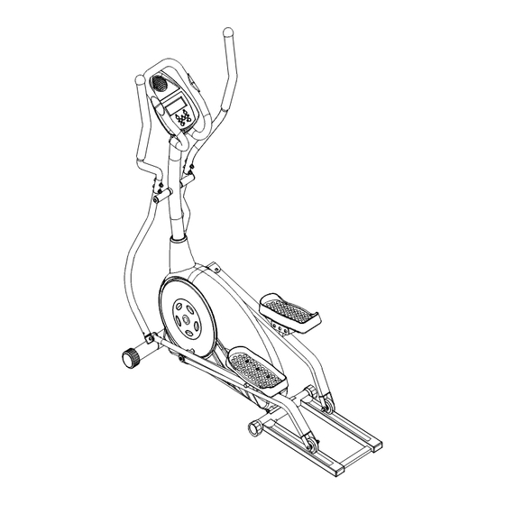
Page 16: Diagram
DIAGRAM Maurice Pincoffs Canada Inc. ©2009 Customer Service 1-888-707-1880 PDF created with pdfFactory trial version www.softwarelabs.com... -
Page 17: Parts List
PARTS LIST KEY NO PART NO Description Specification Q'TY 1711901 Main frame 1711902 Rear stabilizer rail 1711903L Pedal bar left 1711903R Pedal bar right 1711904L Foot pedal tube left 1711904R Foot pedal tube right 1711905 Pedal connect bracket 1711906 U bracket 1711907 Upper U bracket 1711908L... - Page 18 KEY NO PART NO Description Specification Q'TY 1711931 Allen head bolt M8x45mm 1711932 Nylon nut 1711933 Allen head bolt M8x15mm 1711934L Pedal left 1711934R Pedal right 1711935 Machine screw M5x25mm Φ22xΦ16.5x0.5t 1711936 Wave washer 1711937 Machine screw M5x15mm Φ12 1711938 Plug 1711939 Allen head bolt...
- Page 19 KEY NO PART NO Description Specification Q'TY Φ15 1711966 Magnet 1711967L Crank disk left 1711967R Crank disk right 1711968 Machine screw M5x10mm Φ16xΦ6x1.0mm 1711969 Washer 1711970 Hex head bolt M8x20mm Φ400 1711971L Disc cover left Φ400 1711971R Disc cover right 1711972L Pedal axle left 1711972R...
-
Page 20: Trouble Shooting
TROUBLE SHOOTING Problem Cause Correction Adaptor not plugged in or batteries Monitor does not display Plug adaptor in or insert batteries not installed Securely plug sending unit into No speed or distance Sending unit not connected extension wire and the back of displays on the monitor the monitor Sending unit not working properly... -
Page 21: Training Guidelines
TRAINING GUIDELINES Exercise Exercise is one of the most important factors in the overall health of an individual. Listed among its benefits are: ž Increased capacity for physical work (strength endurance) ž Increased cardiovascular (heart and arteries/veins) and respiratory efficiency ž... - Page 22 Specificity Different forms of exercise produce different results. The type of exercise that is carried out is specific both to the muscle groups being used and to the energy source involved. There is little transfer of the effects of exercise, i.e. from strength training to cardiovascular fitness. That is why it is important to have an exercise program tailored to your specific needs.
- Page 23 Don’t push yourself too hard to reach the figures on this table. It can be very uncomfortable if you overdo it. Let it happen naturally as you work through your program. Remember, the target is a guide, not a rule, a little above or below is just fine. Two final comments:(1) don’t be concerned with day to day variations in your pulse rate, being under pressure or not enough sleep can affect it;(2) your pulse rate is a guide, don’t become a slave to it.
- Page 24 STRETCHING Stretching should be included in both your warm up and cool down, and should be performed after 3-5 minutes of low intensity aerobic activity or callisthenic type exercise. Movements should be performed slowly and smoothly, with no bouncing or jerking. Move into the stretch until slight tension, not pain, is felt in the muscle and hold for 20-30 seconds.
- Page 25 INNER THIGH STRETCH TOE TOUCHES Sit with the soles of your feet together with your Slowly bend forward from your waist, letting knees pointing outward. Pull your feet as close your back and shoulders relax as you stretch Into your groin as possible. Gently push your toward your toes.
Need help?
Do you have a question about the 16117119 and is the answer not in the manual?
Questions and answers