Table of Contents

Related Manuals for Toro 74523


Summary of Contents for Toro 74523
- Page 1 Form No. 3400-596 Rev C GrandStand ® Multi Force Mower With 52in or 60in TURBO FORCE ® Cutting Unit Model No. 74523—Serial No. 316000001 and Up Model No. 74529—Serial No. 316000001 and Up *3400-596* C Register at www.Toro.com. Original Instructions (EN)
- Page 2 You may contact Toro directly at www.Toro.com for product WARNING safety and operation training materials, accessory information, help finding a dealer, or to register your product. CALIFORNIA Proposition 65 Warning Whenever you need service, genuine Toro parts, or additional This product contains a chemical or chemicals...
-
Page 3: Table Of Contents
Safety ................4 Servicing the Caster Wheels and Bearings....41 Safe Operating Practices........... 4 Using the Clutch Shim ..........41 Toro Mower Safety ..........6 Checking the Wheel-Lug Nuts........43 Slope Indicator ............7 Checking the Wheel-Hub Nuts.........43 Safety and Instructional Decals ......... 8 Cooling System Maintenance ........43... -
Page 4: Safety
Use extra care when handling fuels. They are flammable only be made by either the manufacturer or an Authorized and vapors are explosive. Toro Dealer. – Use only an approved container. This product is capable of amputating hands and feet. Follow –... -
Page 5: Maintenance And Storage
Maintenance and Storage • Stop on level ground, disengage drives, engage the parking brake, shut off the engine before leaving the • Disengage drives, set the parking brake, shut off the operator's position for any reason, including emptying the engine, and remove the key or disconnect spark-plug wire. catchers or unclogging the chute. -
Page 6: Toro Mower Safety
Toro Mower Safety Slope Operation All slopes and ramps require extra caution. If you feel uneasy The following list contains safety information specific to Toro on a slope, do not mow it. products and other safety information that you must know. -
Page 7: Slope Indicator
Slope Indicator G011841 Figure 3 This page may be copied for personal use. 1. The maximum slope you can safely operate the machine on is 20 degrees. Use the slope chart to determine the degree of slope of hills before operating. Do not operate this machine on a slope greater than 20 degrees. Fold along the appropriate line to match the recommended slope. -
Page 8: Safety And Instructional Decals
Safety and Instructional Decals Safety decals and instructions are easily visible to the operator and are located near any area of potential danger. Replace any decal that is damaged or lost. 93-7818 1. Warning—read the Operator's Manual for instructions on torquing the blade bolt/nut to 115 to 149 N∙m (85 to 110 ft-lb). - Page 9 131-3521 1. Height-of-cut 131-1180 1. Read the Operator's Manual. (A) Short, light grass; dry conditions; maximum dispersion; (B) Bagging setting; (C) Tall, dense grass; wet conditions; maximum ground speed 131-3524 1. Read the Operator's 3. Oil level Manual. 2. Transmission oil 131-3507 1.
- Page 10 131-3536 1. Battery 4. Parking brake 2. Time 5. Engine—start 3. Power takeoff (PTO) 6. Engage the handle bars. 133-4648 1. Read the Operator's Manual for more information on servicing the machine. 133-4604 1. Thrown object 3. Severing hazard of hand hazard—keep bystanders or foot—keep away from away from the machine.
- Page 11 131-3527 1. Warning—read the Operator's Manual. 5. Thrown object hazard—keep bystanders away from the machine. 2. Warning—receive training before operating the machine. 6. Warning—1) Engage the parking brake, shut off the engine, and remove the key from the ignition; 2) Read the Operator's Manual before servicing or performing maintenance.
-
Page 12: Product Overview
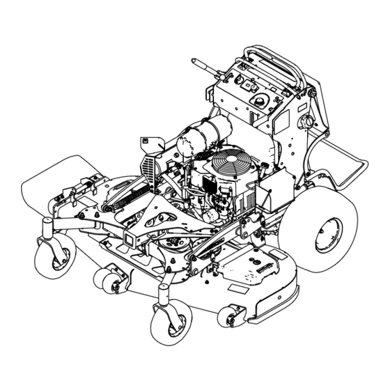
Controls Product Overview Become familiar with all the controls before you start the engine and operate the machine (Figure Figure 4 1. Adjustable caster 9. Control levers 2. Accessory-frame lock 10. Hydraulic tank 3. Anti-scalp roller (60-inch 11. Fuel tank Figure 5 decks only) 1. -
Page 13: Specifications
(Figure Height 122 cm (48 inches) Weight 412 kg (908 lb) Accessory Frame Use the accessory frame to attach only Toro-approved 60-inch Mowers accessories to the machine (Figure 4). Refer to the Operator’s Manual for the accessory for installation instructions. -
Page 14: Attachments/Accessories
Contact your Authorized Service Dealer or Distributor or go to www.Toro.com for a list of all approved attachments and accessories. Think Safety First... -
Page 15: Checking The Engine-Oil Level
DANGER WARNING In certain conditions, gasoline is extremely Gasoline is harmful or fatal if swallowed. Long-term flammable and highly explosive. A fire or explosion exposure to vapors can cause serious injury and from gasoline can burn you and others and can illness. -
Page 16: Operating The Parking Brake
Operating the Parking Brake Operating the Mower-Blade-Control Switch Always set the parking brake when you stop the machine or leave it unattended. Before each use, check the parking brake (PTO) for proper operation. Use the blade-control switch (PTO) in conjunction with the If the parking brake does not hold securely, adjust it;... -
Page 17: Operating The Throttle
Operating the Throttle Using the Fuel-Shutoff Valve The throttle control moves between F and S positions Close the fuel-shutoff valve for transport, maintenance, and (Figure 12). storage (Figure 15). Always use the F position when engaging the mower Ensure that the fuel-shutoff valve is open when starting the blades with the blade-control switch (PTO). -
Page 18: Starting And Shutting Off The Engine
Starting and Shutting Off the Shutting Off the Engine Engine CAUTION Children or bystanders may be injured if they Starting the Engine move or attempt to operate the machine while it is unattended. Important: Do not engage the starter for more than 5 seconds at a time. -
Page 19: The Safety-Interlock System
The Safety-Interlock System Note: The blades should not rotate and the engine should stop running. CAUTION 3. Start the engine and release the parking brake. 4. Move either motion-control lever to the center, If the safety-interlock switches are disconnected or unlocked position. -
Page 20: Driving Forward Or Backward
Operating the Machine with the Driving Forward or Backward Platform Up The throttle control regulates the engine speed as measured in rpm (revolutions per minute). Place the throttle control in Operate the machine with the platform up for the following the F position for best performance. -
Page 21: Stopping The Machine
Note: Remember to remove the key from the ignition switch. CAUTION Children or bystanders may be injured if they move or attempt to operate the machine. Always remove the ignition key and set the parking brake when leaving the machine unattended. Pushing the Machine by Hand The bypass valves allow you to push the machine by hand without the engine running. -
Page 22: Transporting The Machine
Transporting the Machine Loading the Machine Use a heavy-duty trailer or truck to transport the machine. Use extreme caution when loading or unloading machines Ensure that the trailer or truck has all the necessary brakes, onto a trailer or a truck. Use a full-width ramp that is wider lighting, and marking as required by law. - Page 23 WARNING Loading a machine onto a trailer or truck increases the possibility of tip-over and could cause serious injury or death. • Use extreme caution when operating a machine on a ramp. • Use only a full-width ramp; do not use individual ramps for each side of the machine.
-
Page 24: Side Discharging Or Mulching The Grass
Side Discharging or Mulching Adjusting the Height-of-Cut the Grass The height-of-cut can be adjusted from 38 to 127 mm (1-1/2 to 5 inches) in 6 mm (1/4 inch) increments. This mower has a hinged grass deflector that disperses Note: Using a height-of-cut under 51 mm (2 inches) increases clippings to the side and down toward the turf. -
Page 25: Adjusting The Anti-Scalp Rollers
Adjusting the Anti-Scalp Adjusting the Flow Baffle Rollers You can adjust the mower-discharge flow for different types of mowing conditions. Position the cam lock and baffle to 60-inch Models Only provide the best quality of cut. Whenever you change the height-of-cut, adjust the height 1. -
Page 26: Positioning The Flow Baffle
Positioning the Flow Baffle Position C This is the full, open position (Figure 32). Use for this The following figures are only for recommended use. position for the following: Adjustments vary by grass type, moisture content, and the height of the grass. •... -
Page 27: Maintenance
Maintenance Note: Determine the left and right sides of the machine from the normal operating position. Recommended Maintenance Schedule(s) Maintenance Service Maintenance Procedure Interval • Change the engine oil. After the first 8 hours • Check the hydraulic-fluid level. • Change the hydraulic filters and hydraulic fluid. After the first 50 hours •... -
Page 28: Premaintenance Procedures
Premaintenance Lubrication Procedures Grease with No. 2 lithium or molybdenum grease. 1. Disengage the PTO and set the parking brake. Releasing the Cushion for 2. Shut off the engine, remove the key, and wait for all moving parts to stop before leaving the operating Rear Access position. -
Page 29: Greasing The Torsion Idler
Greasing the Torsion Idler Service Interval: Yearly Grease the torsion idler on the mower deck using high-temperature grease at the grease fitting shown in Figure Important: Use only high-temperature grease. Figure 36 1. Seal guard 2. Spacer nut with wrench flats 4. -
Page 30: Engine Maintenance
Engine Maintenance 15. Install the caster bolt and tighten the nut fully. Important: To prevent seal and bearing damage, check the bearing adjustment often by spinning the caster Servicing the Air Cleaner tire. The tire should not spin freely (more than 1 or 2 revolutions) or have any side play. -
Page 31: Servicing The Engine Oil
Installing the Filters Important: To prevent engine damage, always operate the engine with both air filters and the cover installed. 1. If installing new filters, check each filter for shipping damage. Note: Do not use a damaged filter. 2. If you are replacing the safety filter, carefully slide it into the filter body (Figure 38). -
Page 32: Changing The Engine Oil
Checking the Engine-Oil Level Service Interval: Before each use or daily Note: Check the oil when the engine is cold. WARNING Contact with hot surfaces may cause personal injury. Keep your hands, feet, face, clothing and other body parts away the muffler and other hot surfaces. Important: Do not run the engine with the oil level above the Full mark or below the Low mark. - Page 33 4. Shut off the engine, remove the key, and wait for all 5. Slowly pour approximately 80% of the specified oil moving parts to stop before leaving the operating into the filler tube and slowly add the additional oil to position (Figure 41).
-
Page 34: Servicing The Spark Plug
Changing the Engine-Oil Filter Servicing the Spark Plug Service Interval: Every 200 hours Service Interval: Every 200 hours Note: Change the engine-oil filter more frequently when Make sure that the air gap between the center and side operating conditions are extremely dusty or sandy. electrodes is correct before installing the spark plug. -
Page 35: Checking The Spark Arrester
Installing the Spark Plug Fuel System Maintenance Draining the Fuel Tank You can drain the fuel tank by removing it and pouring the fuel out of the fill neck; refer to Removing the Fuel Tank (page 36). You can also drain the fuel tank by using a siphon in the following procedure. -
Page 36: Removing The Fuel Tank
Removing the Fuel Tank Servicing the Fuel Filter 1. Lower the platform. Replacing the Fuel Filter 2. Release the cushion; refer to (page Service Interval: Every 800 hours/Yearly (whichever comes 3. Remove the cross bracket. first) Do not install a dirty filter if it is removed from the fuel line. Note: Wipe up any spilled fuel. -
Page 37: Electrical System Maintenance
Electrical System WARNING Maintenance Incorrect battery-cable routing could damage the machine and cables, causing sparks. Sparks can cause the battery gasses to explode, resulting in Servicing the Battery personal injury. • Always disconnect the negative (black) battery Service Interval: Every 100 hours cable before disconnecting the positive (red) Always keep the battery clean and fully charged. -
Page 38: Installing The Battery
Installing the Battery Charging the Battery Install the battery as shown in Figure WARNING Charging the battery produces gasses that can explode. Never smoke near the battery and keep sparks and flames away from battery. Important: Always keep the battery fully charged (1.265 specific gravity) to prevent battery damage when the temperature is below 0°C (32°F). -
Page 39: Servicing The Fuses
Servicing the Fuses Drive System Maintenance The electrical system is protected by fuses and requires no maintenance. If a fuse blows, check the component or circuit for a malfunction or short. Adjusting the Tracking 1. Release the cushion from the rear of the machine. 2. -
Page 40: Checking The Tire Pressure
Adjusting the Caster-Pivot 6. Check that the machine does not creep from the neutral position with the park brakes disengaged. Bearing 7. Install the fuel tank, if you removed it. Service Interval: Every 500 hours/Yearly (whichever comes 8. Install the cushion. first) 1. -
Page 41: Servicing The Caster Wheels And Bearings
Servicing the Caster Wheels Using the Clutch Shim and Bearings Some later model year units have been built with clutches that contain a brake shim. When the clutch brake has worn to the The caster wheels rotate on a roller bearing supported by a point where the clutch no longer engages consistently, you spanner bushing. - Page 42 A. Loosen both brake mounting bolts 1/2 to 1 full turn as shown in Figure Note: Do not remove the brake pole from the field shell/armature. The brake pole has worn to match the armature and needs to continue to match after you remove the shim to ensure the proper brake torque.
-
Page 43: Checking The Wheel-Lug Nuts
Checking the Wheel-Lug Nuts Cooling System Maintenance Service Interval: After the first 100 hours—Check the wheel-lug nuts. Check and torque the wheel lug nuts to 115 to 142 N∙m (85 Cleaning the Air-Intake Screen to 105 ft-lb). Service Interval: Before each use or daily Checking the Wheel-Hub Nuts Before each use, remove any buildup of grass, dirt, or other debris from the cylinder and cylinder-head cooling... -
Page 44: Brake Maintenance
Brake Maintenance Belt Maintenance Servicing the Brake Replacing the Mower-Deck Belt Before each use, check the brakes on a level surface and slope. Service Interval: Every 100 hours—Check the mower-deck Always set the parking brake when you stop the machine or belt. -
Page 45: Replacing The Transmission Belt
Replacing the Transmission 7. Remove the deck belt from the clutch and clutch stop (Figure 68). Belt 8. Install the new belt. Service Interval: Every 1,000 hours—Replace the 9. Install the tension spring and lower hydraulic hose. transmission belt. 10. Install the drain plugs. 1. -
Page 46: Controls System Maintenance
Controls System Maintenance Adjusting the Motion-Control Levers If the motion-control levers do not align horizontally, adjust the right side motion-control lever. 1. Disengage the PTO, move the motion-control levers to Figure 70 the neutral position, and set the parking brake. 2. -
Page 47: Hydraulic System Maintenance
System hours by a doctor familiar with this type of injury. Gangrene may result if this is ® ™ Hydraulic Fluid Type: Toro HYPR-OIL 500 hydraulic not done. • Keep your body and hands away from Hydraulic System Fluid Capacity: 4.7 L (5 US qt) pinhole leaks or nozzles that eject high-pressure hydraulic fluid. - Page 48 Replacing the Hydraulic Fluid and Note: This allows air to escape the hydraulic system as you add hydraulic fluid. Filters Service Interval: After the first 50 hours Every 500 hours/Yearly (whichever comes first)—Change the hydraulic filters and hydraulic fluid. Change the hydraulic fluid more frequently in severe conditions or in a hot operating climate.
-
Page 49: Mower Deck Maintenance
Bleeding the Hydraulic System Mower Deck The traction system is self-bleeding, however, it may be Maintenance necessary to bleed the system if fluid is changed or after work is performed on the system. Removing the Mower Deck 1. Disengage the PTO and set the parking brake. 2. -
Page 50: Installing The Mower Deck
Mount the front hanger brackets on the inside of the front lift arms for 60-inch decks (Figure 76). Note: Torque the bolts to 38 to 49 N∙m (28 to 36 ft-lb). 4. Install the 2 bolts that you retained to connect the strut bracket to the frame (Figure 74). -
Page 51: Removing The Blades
To ensure optimum performance and continued safety conformance of the machine, use Checking for Bent Blades genuine Toro replacement blades. Replacement blades made 1. Disengage the PTO, move the motion-control levers to by other manufacturers may result in nonconformance with the N position, and set the parking brake. - Page 52 Sharpening the Blades 1. Use a file to sharpen the cutting edge at both ends of the blade (Figure 80). Note: Maintain the original angle. Note: The blade retains balance if the same amount of material is removed from both cutting edges. Figure 80 1.
-
Page 53: Correcting The Mower Quality-Of-Cut
Correcting the Mower Leveling the Mower Deck from Side to Side Quality-of-Cut 1. Loosen the side nut and jam nut in the yokes you want If a deck blade cuts lower than the other, correct it as follows: to adjust (Figure 84). - Page 54 Checking the Mower Deck Front-to-Rear Leveling the Mower Deck from Front to Pitch Rear 1. Adjust the tire pressure in the rear tires to the correct 1. Loosen the jam nut and side bolt in the yokes that you specifications. want to adjust (Figure 86).
-
Page 55: Adjusting The Deck-Lift Spring
Matching the Height-of-Cut Adjusting the Deck-Lift Spring 1. Check the rear tire pressure. Note: Adjusting the deck-lift spring alters how much the deck floats and how much effort it takes to lift the deck when 2. Set the height-of-cut to the 7.6 cm (3 inches) position; using the height-of-cut handle. -
Page 56: Replacing The Grass Deflector
Replacing the Grass Deflector Cleaning WARNING Cleaning under the Mower An uncovered discharge opening could allow the machine to throw objects in the operator's or Service Interval: Before each use or daily bystander's direction and result in serious injury. Remove the grass buildup under the mower daily. Also, contact with the blade could occur. -
Page 57: Storage
Storage 13. Store the machine in a clean, dry, garage or storage area. Remove the key from the ignition switch and store it in a memorable place. Cover the machine to Cleaning and Storage protect it and keep it clean. 1. -
Page 58: Troubleshooting
Troubleshooting Problem Possible Cause Corrective Action The engine does not start, starts hard, or 1. The fuel tank is empty or the shutoff 1. Fill the fuel tank with gasoline and fails to keep running. valve is closed. open the valve 2. - Page 59 Problem Possible Cause Corrective Action The cutting height is uneven. 1. Blade(s) are not sharp. 1. Sharpen the blade(s). 2. Cutting blade(s) is/are bent. 2. Install new cutting blade(s). 3. The mower deck is not level. 3. Level the mower deck side-to-side position.
-
Page 60: Schematics
Schematics Electrical Schematic (Rev. A) - Page 61 Notes:...
- Page 62 Notes:...
- Page 63 Notes:...
- Page 64 Customers who have purchased Toro products outside the United States or Canada should contact their Toro Distributor (Dealer) to obtain guarantee policies for your country, province, or state. If for any reason you are dissatisfied with your Distributor's service or have difficulty obtaining guarantee information, contact the Toro importer. If all other remedies fail, you may contact us at Toro Warranty Company.
Need help?
Do you have a question about the 74523 and is the answer not in the manual?
Questions and answers