Table of Contents
Advertisement
Quick Links
Form No. 3360-931 Rev B
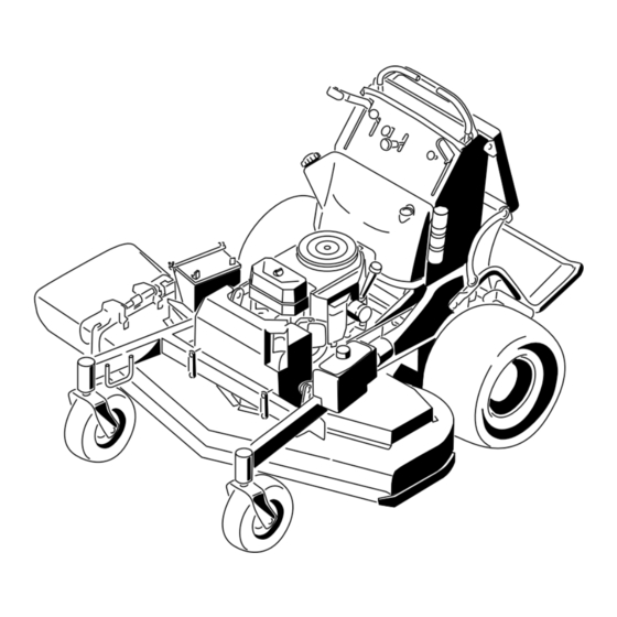
GrandStand
™
Mower
with a 122cm or 132cm TURBO FORCE
®
Cutting Unit
Model No. 74567TE—Serial No. 290000001 and Up
Model No. 74569TE—Serial No. 290000001 and Up
To register your product or download an Operator's Manual or Parts Catalog at no charge, go to www.Toro.com.
Original Instructions (EN)
Advertisement
Table of Contents

Related Manuals for Toro GrandStand 74567TE


Summary of Contents for Toro GrandStand 74567TE
-
Page 1: Cutting Unit
122cm or 132cm TURBO FORCE ® Cutting Unit Model No. 74567TE—Serial No. 290000001 and Up Model No. 74569TE—Serial No. 290000001 and Up To register your product or download an Operator's Manual or Parts Catalog at no charge, go to www.Toro.com. Original Instructions (EN) -
Page 2: Table Of Contents
Vibration.............. 6 additional information, contact an Authorized Service Slope Chart ............7 Dealer or Toro Customer Service and have the model Safety and Instructional Decals ......8 and serial numbers of your product ready. Figure 1 Product Overview ............11 identifies the location of the model and serial numbers Controls ............. -
Page 3: Safety
Servicing the Spark Plug ........34 comply with these safety instructions. Fuel System Maintenance ........35 Toro designed and tested this mower for reasonably safe Draining the Fuel Tank........35 service; however, failure to comply with the following Servicing the Fuel Filter ........36 instructions may result in personal injury. - Page 4 – inadequate braking • Mow only in daylight or in good artificial light. – the type of machine is unsuitable for it’s task • Avoid operating the lawn mower in wet grass, where feasible. – lack of awareness of the effect of ground conditions, especially slopes •...
-
Page 5: Toro Mower Safety
• Keep all movement on slopes slow and gradual. Do not make sudden changes in speed or direction. The following list contains safety information specific to Toro products and other safety information you must • Mow slopes side to side. know. -
Page 6: Sound Pressure
• Never tamper with safety devices. Check safety systems for proper operation before each use. • Use only genuine replacement parts to ensure that original standards are maintained. • Check brake operation frequently. Adjust and service as required. Sound Pressure This unit has an equivalent continuous A-weighted sound pressure level at the operator’s ear of 91 dBA for model 74567TE and 94 dBA for model 74569TE,... -
Page 7: Slope Chart
Slope Chart... -
Page 8: Safety And Instructional Decals
Safety and Instructional Decals Safety decals and instructions are easily visible to the operator and are located near any area of potential danger. Replace any decal that is damaged or lost. 93-7010 107-2131 1. Thrown object hazard—keep bystanders a safe distance from the machine. - Page 9 114–3598 1. Tipping hazard—do not mow up or down slopes greater 117-0456 than 10 degrees; do not mow across slopes greater than 1. Height of cut (HOC)—low 3. Height of cut (HOC)—high 18 degrees. 2. Height of cut (HOC)—medium 115-4186 1.
- Page 10 Manufacturer’s Mark 1. Indicates the blade is identified as a part from the original machine manufacturer. Battery Symbols Some or all of these symbols are on your battery 1. Explosion hazard 6. Keep bystanders a safe distance from the battery. 2.
-
Page 11: Product Overview
117–3626 1. Warning—read the Operator’s Manual. 5. Thrown object hazard—keep bystanders a safe distance from the machine. 2. Warning—do not operate this machine unless you are trained. 6. Warning—engage the parking brake, stop the engine and remove the spark plug wire before performing any maintenance on the machine. -
Page 12: Specifications
(Figure 5). enhance and expand its capabilities. Contact your Authorized Service Dealer or Distributor or go to www.Toro.com for a list of all approved attachments and accessories. Specifications Note: Specifications and design are subject to change without notice. -
Page 13: Operation
Operation In certain conditions during fueling, static Adding Fuel electricity can be released causing a spark which can ignite the gasoline vapors. A fire Use Unleaded Regular Gasoline suitable for or explosion from gasoline can burn you and automotive use (85 pump octane minimum). Leaded others and can damage property. -
Page 14: Checking The Engine Oil Level
Breaking In a New Machine Important: Do not use fuel additives containing methanol or ethanol. New engines take time to develop full power. Mower Add the correct amount of gas decks and drive systems have higher friction when new, stabilizer/conditioner to the gas. placing additional load on the engine. -
Page 15: Operating The Mower Blade Control Switch (Pto)
G009174 Figure 9 Figure 7 1. Parking brake engaged 2. Parking brake released Operating the Throttle Releasing the Parking Brake The throttle control can be moved between Fast and Slow positions (Figure 10). Pull the brake lever back and over into the slot and push the parking brake lever forward. -
Page 16: Operating The Ignition Switch
Using the Speed Control Lever This machine has a speed control lever that sets the speed of the machine. This can be adjusted to the operator’s desired speed. It is recommended to use the slowest speed for new operator’s. 1. Move the speed control lever to set the desired speed. -
Page 17: Starting And Stopping The Engine
Figure 15 7. Turn the ignition key to the Start position G008948 (Figure 12). When the engines starts, release the key. Figure 14 Important: Do not engage starter for more 1. On 2. Off than 5 seconds at a time. If the engine fails to start allow a 15 second cool-down period between attempts. -
Page 18: The Safety Interlock System
Stopping the Engine The Safety Interlock System Children or bystanders may be injured if they If safety interlock switches are disconnected move or attempt to operate the tractor while it or damaged the machine could operate is unattended. unexpectedly causing personal injury. Always remove the ignition key and set the •... -
Page 19: Operating The Platform
Operating the Platform 1. Start the engine; refer to Starting and Stopping the Engine in Operation. The machine can be used with the platform in the up 2. Set the parking brake. or down position. It is the operator’s preference on which position to use. -
Page 20: Driving Forward Or Backward
2. Move the right side motion control lever to the center, un-locked position. Figure 20 1. Front reference bar 4. Right control lever 2. Left control lever 5. Right control lever in the neutral lock position 3. Rear reference bar Figure 19 3. -
Page 21: Stopping The Machine
Set the parking brake when you leave the machine; refer to Setting the Parking Brake in Operation. Remember to remove the key from the ignition switch. Children or bystanders may be injured if they move or attempt to operate the tractor while it is unattended. -
Page 22: Transporting Machines
3. Release the parking brake. extend beyond the rear tires is recommended instead of individual ramps for each side of the unit (Figure 25). 4. Push the machine to the desired location. Having a full width ramp provides a surface for the 5. -
Page 23: Side Discharging Or Mulching The Grass
Adjusting the Height-of-Cut The height-of-cut can be adjusted from 1 to 4-1/2 inch (25 to 114 mm) in 1/4 inch (6 mm) increments. 1. Move the height-of-cut lever to the transport position (all the way up). 2. Select a hole in the height-of-cut bracket corresponding to the height-of-cut desired and, insert the pin (Figure 26). -
Page 24: Positioning The Flow Baffle
• Use in tall, dense grass mowing conditions. • Use in wet conditions. • Lowers the engine power consumption. • Allows increased ground speed in heavy conditions. • This position is similar to the benefits of the Toro SFS mower. -
Page 25: Using Weights
Figure 30 Using Weights • Weights are installed to improve handling, balance and improve performance. Weights can be added or removed to create optimized performance under different mowing conditions and for operator preference. • It is recommended that weights be added or removed one at a time until the desired handing and balance is achieved. -
Page 26: Maintenance
Maintenance Note: Determine the left and right sides of the machine from the normal operating position. Recommended Maintenance Schedule(s) Maintenance Service Maintenance Procedure Interval • Change the engine oil. • Check the hydraulic fluid level. After the first 8 hours •... -
Page 27: Premaintenance Procedures
Premaintenance Procedures Raising the Mower for Access The front of the mower can be raised and supported on its back for access under the machine for maintenance. 1. Raise the platform. Refer to Operating the Platform in Operation. 2. Remove the battery. Figure 32 3. -
Page 28: Remove The Cushion For Rear Access
Figure 34 1. Pin 3. Cotter pin 2. Cushion bracket 4. Plastic bushing Figure 33 1. Remove battery 2. With two people, lift the front end of the mower (ensure the platform is up) Remove the Cushion for Rear Access The cushion can be removed for rear access to the machine for maintenance or adjustment. -
Page 29: Lubrication
Lubrication Grease with No. 2 general purpose lithium base or molybdenum base grease. Lubricate the traction rollers with a dry lubricant (PTFE). How to Grease 1. Disengage the PTO and set the parking brake. 2. Stop the engine, remove the key, and wait for all moving parts to stop before leaving the operating position. -
Page 30: Engine Maintenance
Engine Maintenance Servicing the Air Cleaner Service Interval/Specification Inspect the foam and paper elements and replace them if they are damaged or excessively dirty. Note: Service the air cleaner more frequently (every few operating hours) if the operating conditions are Figure 38 extremely dusty or sandy. -
Page 31: Servicing The Engine Oil
Installing the Foam and Paper Elements Important: To prevent engine damage, always operate the engine with the complete foam and paper air cleaner assembly installed. 1. Carefully slide the foam element onto the paper air cleaner element (Figure 39). 2. Place the air cleaner assembly onto the air cleaner base and secure it with the 2 wing nuts (Figure 39). -
Page 32: Changing The Engine Oil
Contact with hot surfaces may cause personal injury. Keep hands, feet, face, clothing and other body parts away the muffler and other hot surfaces. Important: Do not overfill the crankcase with oil because damage to the engine may result. Do not run engine with oil below the low mark because the engine may be damaged. -
Page 33: Changing The Engine Oil Filter
3. Disengage the PTO, move the motion control levers to the neutral locked position and set the parking brake. 4. Stop the engine, remove the key, and wait for all moving parts to stop before leaving the operating position (Figure 42). G008796 Figure 43 Changing the Engine Oil Filter... -
Page 34: Servicing The Spark Plug
Type for 19hp Engines: Champion ® RCJ8Y or equivalent Type for 23hp Engines: NGK ® BPR4ES or equivalent Air Gap: 0.030 inch (0.75 mm) Removing the Spark Plug 1. Disengage the PTO, move the motion control levers to the neutral locked position and set the parking brake. -
Page 35: Fuel System Maintenance
Installing the Spark Plug Fuel System Tighten the spark plug(s) to 16 ft.-lb (22 N-m). Maintenance Draining the Fuel Tank Note: There is no other recommended way to drain fuel from the tank, other than using a syphon pump. A syphon pump can be purchased at a hardware store. -
Page 36: Servicing The Fuel Filter
Servicing the Fuel Filter Electrical System Maintenance Replacing the Fuel Filter Service Interval: Every 400 hours/Yearly (whichever Servicing the Battery comes first) Always keep the battery clean and fully charged. Use Never install a dirty filter if it is removed from the fuel a paper towel to clean the battery case. -
Page 37: Installing The Battery
Incorrect battery cable routing could damage the machine and cables causing sparks. Sparks can cause the battery gasses to explode, resulting in personal injury. • Always Disconnect the negative (black) battery cable before disconnecting the positive (red) cable. • Always Reconnect the positive (red) battery cable before reconnecting the negative (black) cable. -
Page 38: Servicing The Fuses
Important: Always keep the battery fully charged (1.265 specific gravity). This is especially important to prevent battery damage when the temperature is below 32°F (0°C). 1. Remove the battery from the chassis; refer to Removing the Battery. 2. Check the electrolyte level; refer to Checking the Figure 51 Electrolyte Level. -
Page 39: Drive System Maintenance
Drive System Maintenance Adjusting the Tracking Note: Determine the left and right sides of the machine from the normal operating position. 1. Push both control levers forward the same distance. 2. Check if the machine pulls to one side. If it does, stop the machine and set the parking brake. -
Page 40: Checking The Tire Pressure
Checking the Tire Pressure Service Interval: Every 50 hours/Monthly (whichever comes first) Maintain the air pressure in the rear tires at 12-14 psi (83-97 kPa). Uneven tire pressure can cause an uneven cut. Note: The front tires are semi-pneumatic tires and do not require air pressure maintenance. -
Page 41: Adjusting The Electric Clutch
Cooling System 3. Remove the other bushing from the wheel hub and clean any grease and dirt from the wheel hub Maintenance (Figure 57). 4. Inspect the roller bearing, bushings, spanner bushing and inside of the wheel hub for wear. Replace any Cleaning the Air Intake Screen defective or worn parts (Figure 57). -
Page 42: Brake Maintenance
Brake Maintenance 9. Tighten the jam nut (Figure 60). 10. Check the brake operation again; refer to Checking the Brake. Servicing the Brake Before each use, check brakes on both a level surface and slope. Always set the parking brake when you stop the machine or leave it unattended. -
Page 43: Belt Maintenance
Belt Maintenance Replacing the Mower Deck Belt Service Interval: Every 100 hours—Check the mower deck belt. Squealing when the belt is rotating, blades slipping when cutting grass, frayed belt edges, burn marks and cracks are signs of a worn deck belt. Replace the deck belt if any of these conditions are evident. -
Page 44: Controls System Maintenance
Controls System Maintenance Adjusting the Motion Control Handle Positions Adjusting the Right Side Motion Control Lever If the motion control levers do not align horizontally, adjust the right side motion control lever. Note: Adjust the horizontal alignment before the front to back alignment. -
Page 45: Motion Control Levers
Figure 65 1. Switch screws 3. Nut and bolt 2. Cam Figure 66 9. After the cam is adjusted, the lever switch needs to 1. Switch 3. Right motion control lever be checked. in the neutral unlocked position 10. Check the gap between the control lever and switch 2. -
Page 46: Adjusting The Speed Control Lever
3. Move the HOC lever to the 1 inch height-of-cut position (lowest position) (Figure 69). 4. Move the speed control lever to the fast position (Figure 69). 5. Hold the motion control levers fully forward. Figure 67 1. Left motion control lever 3. -
Page 47: Hydraulic System Maintenance
Service Interval: After the first 8 hours Hydraulic fluid escaping under pressure can Every 50 hours penetrate skin and cause injury. Hydraulic Oil Type: Toro ® 15w-50 hydraulic oil or • If hydraulic fluid is injected into the skin ®... -
Page 48: Bleeding The Hydraulic System
3. Remove hydraulic reservoir cap and temporarily cover opening with a plastic bag and rubber band to prevent all hydraulic fluid from draining out. 4. Locate the filter under the fuel tank and place drain pan under filter (Figure 72). Figure 73 1. -
Page 49: Mower Deck Maintenance
Checking the Hydraulic Lines Mower Deck Service Interval: Every 100 hours Maintenance Check hydraulic lines and hoses for leaks, loose fittings, kinked lines, loose mounting supports, wear, weather Servicing the Cutting Blades and chemical deterioration. Make necessary repairs before operating. To ensure a superior quality of cut, keep the blades sharp. -
Page 50: Removing The Blades
To ensure optimum brake. performance and continued safety conformance of the machine, use genuine Toro replacement blades. 2. Stop the engine, remove the key, and wait for all Replacement blades made by other manufacturers may moving parts to stop before leaving the operating result in non-conformance with safety standards. -
Page 51: Correcting The Mower Quality Of Cut
the end of the sail area only (Figure 76). Repeat this 2. Stop the engine, remove the key, and wait for all procedure until the blade is balanced. moving parts to stop before leaving the operating position. Disconnect the spark plug wire(s) from the spark plug(s). - Page 52 1. Change the rear tire pressure. Do this to the corresponding side that needs adjustment. 2. Locate the U-plates on the side of the engine deck (Figure 81). 3. Loosen the U-plate on one side and adjust it up or down to make the difference between measurements B and C no more than a 1/4 inch (6 mm) (Figure 81).
- Page 53 5. Check the front-to-rear pitch of the cutting unit. 6. If the dimensions are not correct, adjust the front and rear nuts on either side to get the correct front-to-rear pitch (Figure 84). Figure 85 1. Measure from a level 2.
-
Page 54: Replacing The Grass Deflector
Replacing the Grass Deflector Cleaning Cleaning Under the Mower An uncovered discharge opening could allow Service Interval: Before each use or daily the lawn mower to throw objects in the operator’s or bystander’s direction and result Remove the grass buildup under the mower daily. in serious injury. -
Page 55: Storage
Storage and distribute the oil inside the cylinder. Install the spark plug(s). Do not install the wire on the spark plug(s). Cleaning and Storage 10. Check and tighten all bolts, nuts, and screws. Repair 1. Disengage the power take off (PTO), set the parking or replace any part that is damaged or defective. -
Page 56: Troubleshooting
Troubleshooting Problem Possible Cause Corrective Action Engine will not start, starts hard, or fails 1. Fuel tank is empty. 1. Fill fuel tank with gasoline. to keep running. 2. Choke is not on. 2. Move the choke lever to choke position. 3. - Page 57 Problem Possible Cause Corrective Action Blades do not rotate. 1. Pump drive belt is worn, loose or 1. Check the belt tension. broken. 2. Install drive belt and check adjusting 2. Pump drive belt is off pulley. shafts and belt guides for correct position.
-
Page 58: Schematics
Schematics Hydraulic Schematic (Rev. A) - Page 59 Electrical Schematic (Rev. A)
- Page 60 Notes:...
- Page 61 Notes:...
- Page 62 Notes:...
- Page 63 Spypros Stavrinides Limited Cyprus 357 22 434131 Surge Systems India Limited India 91 1 292299901 T-Markt Logistics Ltd Hungary 36 26 525 500 Toro Australia Australia 61 3 9580 7355 Toro Europe BVBA Belgium 32 14 562 960 374-0102 Rev D...
- Page 64 1. Contact your seller to arrange service of the product. If for any reason it is impossible for you to contact your seller, you may contact any Toro Authorized distributor to arrange service. 2. Bring the product and your proof of purchase (sales receipt) to your seller of the Service Dealer.