Table of Contents
Advertisement
Quick Links
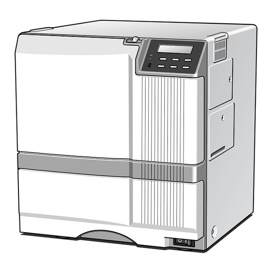
SUBLIMATION TYPE RETRANSFER PRINTER
EDI secure
XID580i
SPECIFICATIONS
Recording method : Sublimation type retransfer
Feed format
: Automatic feed
Recording density : 300 dpi
: 256 gradations for each
Expression gradation
color
Printing time
: Approx. 29 seconds (for
single-sided printing,
excluding data transfer
time)
Interface
: USB2.0 (standard)
Operating environment conditions
Temperature: 15°C ~ 30°C
Humidity: 35% ~ 70%
(no condensation)
Storage environment conditions
Temperature: -15°C ~ 55°C
Humidity: 20% ~ 80%
Power supply
: 100 — 120 V AC/
220 — 240 VAC
(allowance±10%)
Current dissipation : 7.0A (for 100V system)/
5.0A (for 200V system)
Mass
: Standard 22.0kg
Excluding the built-in
magnetic encoder
SERVICE MANUAL
Accessories
: Power cable
* The detached power cords and the Instruction
manual vary according to model and country of
purchase.
CX21ICL Series (Large-type IC unit)
For 120 V AC
Power supply
x 1
Dark gray (North America)
For 220 to 240 V AC
Current dissipation : 500mA,
x 1
Mass
(Europe)
Dimension (mm)
Instruction manual
Accessories
English
x 1
CX21ICS Series (Small-type IC unit)
Power supply
Mass
Dimension (mm)
Card stacker
Accessories
×1
Ink ribbon cassette
Products sold separately
×1
Retransfer film cassette
×1
Jog lever (contained in the
card tray)
×1
: Fed from the printer.
5V±5% DC, 12V±5% DC, 24V±5%
DC
300mA,
: 3.5kg
: 110(W) × 221(D) × 255(H)
: Joint plate × 1
Inter-unit cable × 1
: Fed from the printer.
: 0.5kg
: 50(W) × 152(D) × 115(H)
: Screw (with washer) × 3
Screw (without washer) × 2
: Ink ribon, retransfer film
: Cleaning card
1,000 frames/set
10 card /set
Model : CY-P340A
Model : CX210-CC1
: Laminator Unit :
Model : ILU
: Card tray
When setting paper feeding feature on the right
Model: CF-3NTR
: Hand gloves M Size (U105-M)
L Size (U105-L)
KAS-T099-002
May 2006
1A
Advertisement
Table of Contents

Related Manuals for Digital Identification Solutions EDI secure XID580i


Summary of Contents for Digital Identification Solutions EDI secure XID580i
-
Page 1: Service Manual
SERVICE MANUAL SUBLIMATION TYPE RETRANSFER PRINTER EDI secure XID580i SPECIFICATIONS Recording method : Sublimation type retransfer Accessories : Power cable CX21ICL Series (Large-type IC unit) Feed format : Automatic feed For 120 V AC Power supply : Fed from the printer. Recording density : 300 dpi 5V±5% DC, 12V±5% DC, 24V±5% : 256 gradations for each... -
Page 2: Table Of Contents
CONTENTS IMPORTANT SAFETY PRECAUTIONS 2.10.1 Installation of the Platen Solenoid ........22 2.11 REMOVAL OF THE POWER SUPPLY UNIT ......22 INSTRUCTIONS 2.12 REMOVAL OF SENSORS AND SWITCHES ....... 23 MODEL NAME ................. 1 2.12.1 Removal of the Cam Sensor .......... 23 2.12.2 Removal of the Card Outlet Sensor ....... - Page 3 LARGE IC UNIT ..............2.3.3 Times ................40 2.3.4 Test Select ................ 40 1. Removal of Each Part ..............73 2.4 Diag. Test ................40 1.1 Removal of the Top Cover ............73 2.4.1 Sensor ................40 1.2 Removal of the Front Panel ............ 73 2.4.2 Actuator ................
-
Page 4: Important Safety Precautions
Important Safety Precautions Prior to shipment from the factory, VDS products are strictly inspected to conform with the recognized product safety and electrical codes of the countries in which they are to be sold. However, in order to maintain such compliance, it is equally important to implement the following precautions when a set is being serviced. - Page 5 • Safety Check after Servicing Examine the area surrounding the repaired location for damage or deterioration. Observe that screws, parts and wires have been returned to original positions, Afterwards, perform the following tests and confirm the specified values in order to verify compliance with safety standards.
-
Page 6: Model Name
MODEL NAME The letters and numbers following the model name are used to differentiate between destinations and specifications. Model name: XID580i - # 1. Detailed specifications # Portion – Internal option Nil ..No option (Standard model) B ... Equipped with ISO magnetic encorder / IC contact... -
Page 7: How To Connect Separately Sold Parts
HOW TO CONNECT SEPARATELY SOLD PARTS 1. Connecting the Small-type IC Unit Remove the cover on the side of the printer. Remove the screw, and then raise the cover to remove it. Connect the connector. Please note that the connector has directionality. Install the unit with three screws. -
Page 8: Connection Of The Magnetic/Contact-Type Ic Encoder
2. Connection of the Magnetic/Contact-type IC Encoder When the separately sold magnetic/contact-type IC encoder is to be connected to a standard printer, connect it accord- ing to the following procedure. For details in regard to the removal method for each part, refer to “Removal and exchange of the Main Parts”. 1) Remove the top cover. -
Page 9: Connecting Card Tray
3. Connecting card tray Upon issuing the card using paper feeding feature on the right, as the NG cards transported to the printer will be ejected, replace the standard hopper unit with an optional card tray. Mount the card tray according to the following procedures: 1. -
Page 10: Block Diagram
BLOCK DIAGRAM 1. OVERALL BLOCK DIAGRAM... -
Page 11: Block Diagram Of Primary Side Of Powerunit
2. BLOCK DIAGRAM OF PRIMARY SIDE OF POWERUNIT... -
Page 12: Interlock Sw Block Diagram
3. INTERLOCK SW BLOCK DIAGRAM... -
Page 13: Block Diagram Of The Fpga Circumference
4. BLOCK DIAGRAM OF THE FPGA CIRCUMFERENCE ON A MAIN BOARD Flash Memory 32bit CPU BUS 16bit SDRAM Data 4MWordx16bit CPU I/F BLOCK Step Motor INTERNAL Speed Up/Down CLOCK Table GENERATOR (CPU generates the table data.) Motor Solenoid MOTOR SDRAM I/F BLOCK Control CONTROL Heater control... -
Page 14: Wiring Diagram
WIRING DIAGRAM Thermostat... -
Page 15: Main Parts Layout
Main Parts Layout 1. Sensors Ink FG sensor (encorder circuit board) Retransfer film mark sensor (circuit board) Ink start position sensor (circuit board) Retransfer roller sensor Turnover card sensor (circuit board) Card outlet sensor Turnover initial position sensor Bend remedial roller sensor Card supply sensor No card... -
Page 16: Motor-Related
3. Motors Retransfer film supply motor Ink take-up motor Retransfer film take-up motor Ink supply Motor Cam motor Turn over motor Card feed Turn over motor feed motor Card pick up motor 4. Solenoid Platen Solenoid Rear veiw... -
Page 17: Switch-Related
5. Switches Door interlock switch Cassette interlock switch Cleanning roller interlock switch Card tray interlock switch 6. Circuit Boards, Power Supply Unit, and Fans Front PWB Drive PWB Power supply unit Heater protector MAIN PWB... - Page 18 Ventilation fan Ventilation fan Thermal head cooling fan Card cooling fan...
-
Page 19: Rf-Id
7. RF-ID RF-ID unit... -
Page 20: Removal And Exchange Of The Main Parts
REMOVAL AND EXCHANGE OF THE MAIN PARTS 1. CHECKING AT THE TIME OF SERVICING When confirming the symptoms, swing the power supply unit down as shown in the following figure and check the inside. 1.1 REMOVE THE TOP COVER AND THE 1.2 REMOVE THE MG CIRCUIT BOARD. -
Page 21: Swing Down The Power Supply Unit
1.3 SWING DOWN THE POWER SUPPLY UNIT. Screw A Thermostat wire 1) Remove the two screws B on both sides. 2) Loosen the four screws A on both sides. 3) Raise the power supply unit and swing it down. 4) Remove the thermostat cable from the clamper, raise the power supply unit once, and then swing it down. -
Page 22: Removal Of The Cam Motor
CAUTIONS FOR INSTALLATION AND 2.2 REMOVAL OF THE CAM MOTOR CLEANING OF BOTH ROLLERS 1) Remove the two screws A. 1) The oil bearing is on the tip of the roller assembly. Please use a long screwdriver for the lower screw. Do not forget it at the time of installation and re- If the power supply unit is in the way, raise it once moval. -
Page 23: Installation Of The Cam Motor
2.2.1 Installation of the Cam Motor 2.3 REMOVAL OF THE RETRANSFER FILM SUPPLY MOTOR 1) The gear of the cam motor has a phase. When it is removed at the time of roller cleaning, exchange, 1) Remove the ink ribbon and the retransfer film cas- etc., it can be installed again in the same condition, sette. -
Page 24: Installation Of The Retransfer Film Supply Motor
2.3.1 Installation of the Retransfer Film Supply Motor 1) When the motor has been disassembled or ex- changed, first the belt tension must be adjusted. 2) After assembly has been performed, leave the screw Tighten the screw B securely to turn the motor in arrow direction to tighten the belt, and then tighten the screw A securely. -
Page 25: Removal Of The Retransfer Film Take Up Film Winding Motor
2.4 REMOVAL OF THE RETRANSFER FILM TAKE UP FILM WINDING MOTOR Ink supply motor Ink take-up motor With the drive circuit board removed, the Retransfer film take up motor can be removed after the screw in the above figure has been removed. (Refer to a front page.) KJJ46271-001x2 2.5 REMOVAL OF THE CARD FEED MOTOR 1) Remove the tensioning spring... -
Page 26: Removal Of The Ink Supply Motor And The Ink Take-Up Motor
2.6 REMOVAL OF THE INK SUPPLY MO- REMOVAL OF THE FRONT PANEL TOR AND THE INK TAKE-UP MOTOR 1) Remove the retransfer film and the ink ribbon cas- 1) When there is an MG circuit board, remove the cir- sette. cuit board screws and move the circuit board to the side. -
Page 27: Removal Of The Platen Solenoid
2.10 REMOVAL OF THE PLATEN SOLENOID 1) Remove the drive circuit board. 2.11 REMOVAL OF THE POWER SUPPLY UNIT 2) Disengage the wire from the clamp. (2 places) 1) Disconnect the wires and the connectors. 3) Remove the two screws and then remove the so- 2) Remove the two screws lenoid support... -
Page 28: Removal Of Sensors And Switches
2.12 REMOVAL OF SENSORS AND SWITCHES 2.12.3 Removal of the Ink Encoder Circuit Board 2.12.1 Removal of the Cam Sensor Function Function The ink feed quantity is decided by the pulses of this This sensor decides the origin position for pressurizing encoder. -
Page 29: Removal Of The Turnover Initial Position Sensor
2.12.5 Removal of the Turnover Initial Position 2.12.8 Removal of the Retransfer roller/Remedial sensor Roller Sensor Function Function This sensor decides the origin position for the turn unit. This sensor detects the origin of the retransfer roller and the bend remedial roller. 1) Refer to section 2.7 and remove the turnover and Energization is performed only when a roller is in this card feed motor. -
Page 30: Removal Of The Retransfer Film Mark/Ink Start Position
2.12.9 Removal of the Retransfer Film Mark/Ink 2.12.10 Removal of the C.L. Interlock Circuit Board Start Position Sensor Circuit Board and the and the Card Supply Sensor Card Edge Sensor Function • Function C.L. interlock switch This sensor detects the presence or absence of the •... -
Page 31: Removal Of The Door Interlock Circuit Board
2.12.11 Removal of the Door Interlock Circuit Board 2.12.12 Removal of the Cassette Interlock Circuit Board Function Function This circuit board detects opening of the front door. This circuit board detects the presence or absence of The DC 24 V power put out from the power supply unit the retransfer film and the ink ribbon cassette. -
Page 32: Removal Of The Card Tray Interlock Circuit Board
2.12.13 Removal of the Card Tray Interlock Circuit 2.13 REMOVAL OF THE TURNOVER UNIT Board 1) Refer to section 2.9 and remove the front panel. Function 2) Refer to section 2.8 and remove the turnover motor This circuit board detects whether the card tray is pres- and the turnover card feed Motor. -
Page 33: Fan Removal
2.14 FAN REMOVAL 2.14.1 Removal of the Thermal Head Cooling Fan 2.14.3 Removal of the Card Cooling Fan 1) Remove the two screws and the air duct 1) Refer to section 2.9 and remove the front panel. 2) The thermal head cooling fan can be removed after 2) The card cooling fan can be removed after the two the two screws have been removed. -
Page 34: Removal Of The Ventilation Fan
2.14.4 Removal of the Ventilaion Fan 1) Remove the rear panel and the junction connector. 2) Remove the two screws for the fan. Remove the clump QYSDSP 4008N Remove the junction connctor Rear Panel SA QYSPSPD3030N Rear Panel SA... -
Page 35: Roller Removal
2.15 ROLLER REMOVAL 2.15.1 Feed Roller Removal 1) Refer to section 2.9 and remove the front panel. 2) Remove the card feed motor and the retransfer roller as required. 3) Tension adjustment is required for the belt at the front. Please refer to the following figure. A side with the stage JOG DIAL SA (Use for 5 only) -
Page 36: Platen Roller Assy Removal
2.15.2 Platen Roller Assy Removal 1) Remove the thermal head to prevent damage to it. 2) After removing the thermal head, remove the front panel , E-ring and the worm screw , then the platen roller can be removed. Be careful not to damage the platen roller, other- wise print quality may be affected. -
Page 37: Circuit Board Removal
2.16 CIRCUIT BOARD REMOVAL 2.16.1 Removal of the Main Circuit Board 1) When the three screws are removed and the cir- cuit boards are pulled out. Caution at the time of exchange of the Main circuit board 1) Values set in user mode and service mode are stored on the Main circuit board.Accordingly, when the cir- cuit board has been replaced by a new one, these set values must be stored. -
Page 38: Thermal Head Exchange Method
2.17 Thermal Head Exchange Method 1) Remove the ink ribbon and the retranster film cassette. 2) When the locking claws on both sides of the head are spread, the connector can be disconnected. Remove the connector by pulling it. 3) Remove the screw . - Page 39 The check after head exchange After thermal head is exchanged, a printing position may move in the direction of Y. In this case, please adjust in the following procedures. Enter into “Service mode”, “Maintenance” and “Offset Prt Y”. See the next page. 1) Determines the displacement amount according to the print results (those owned by the user).
-
Page 40: Use Of Service Mode
USE OF SERVICE MODE At the time of operation by the user, the "User mode" is used, while the "Service mode" is used at the time of servicing. Refer to the instruction manual for the user mode. 1) Fine adjustment of the printing position 2) Printing of the built-in test pattern 3) Individual operation of motors 1. - Page 41 >>> >>> Card Feed Mo. Card Feed Mo. Card feed motor Testing.. [ENTER] [MENU] >>> >>> Turn Over Mo. Turn Over Mo. Turnover motor Testing.. [ENTER] [MENU] >>> >>> Turnover card feed motor Turn Feed Mo. Turn Feed Mo. Testing.. [ENTER] [MENU] >>>...
-
Page 42: Explanation Of The Various Modes
2. Explanation of the Various Modes B=2.07mm LEFT RIGHT 2.1 Download When changing the version of firmware inside the printer, A=2.15mm BACK FPGA table or FPGA firmware, refer to the “XID580i main- tenance CD-ROM” distributed separately. 2.2 Maintenance 2.2.1 Offset Prt Y Setting For example, when printing with this printer is to be done on preprinted cards and the position relation is not cor- FRONT... -
Page 43: Offset Trf X Setting
2.2.3 Offset Trf X Setting 2.2.6 Device Type Setting The device type of SCSI Standerd is switched. Normally 1) Determine the displacement amount according to "Printer" is used. the print results (those owned by the user). Every step corresponds to a displacement of about 0.17 2.2.7 Card Fan Setting mm. -
Page 44: Off-Line Test
2.3 Off-line Test This is used to print the built-in test pattern of this printer and for execution of an MG self-test. 2.3.1 Pattern setting This printer has seven types of built-in printing patterns. Select a pattern and press the "ENTER" button to store it. Return to the initial pattern is made when the power is cut. -
Page 45: Printing Side
2.3.2 Printing Side 2.4.2 Actuator It is possible to operate each motor individually and to check for mo- Selection whether test printing is to be done on one side tor defects and to check the operation of the mechanisms. or both sides. When two cassettes or a door are open, the power supply to the motor is cut, it will not operate, and inspection should be performed. -
Page 46: Memory
2.4.3 Memory The following table shows reference values. The picture memory SDRAM on the Main PWB is tested. Heat roller Ambient temperature Thermal head The buzzer sounds in case of an error. The error LED also thermistors thermistor thermistor will light. Temperature Indicated Temperature... -
Page 47: Operation Of The Mechanism
OPERATION OF THE MECHANISM The operation from card supply via card transport and printing to retransfer will be explained using a timing chart. The entire timing chart is shown below. The individual tasks (programs) operate independently. 1. Single-side Printing Printing Retransfer Printing task Printing... -
Page 48: Card Supply And Card Feed
4. Card Supply and Card Feed Period : The turnover motor operates and the turno- ver unit is moved to the card supply position. (Vertical position) Period : The card pick-up motor operates and a card is supplied from the hopper. The turnover card feed motor also operates at the same time. - Page 49 Turnover card sensor Card supply sensor Turnover card feed motor Cleaning roller Card supply roller Card edge sensor Card pickup motor Card feed motor Turnover unit (printing position) NG card outlet roller Card supply roller...
-
Page 50: Printing Operation
5. Printing Operation Platen solenoid Retransfer film supply motor Retransfer film take-up motor Ink take-up motor Ink supply motor Period : The thermal head energization ON signal is sent to the power supply unit. 664dot Head voltage (Vth) is put out from the power supply unit. - Page 51 Retransfer film supply motor Ink take-up motor Ink supply motor Retransfer film take-up motor Thermal head Platen roller Retransfer film Ink ribbon Platen roller Thermal head...
-
Page 52: Retransfer Operation
6. Retransfer Operation Card feed motor Retransfer film supply motor Retransfer film take-up motor Cam motor Card edge sensor Card outlet sensor Retransfer film mark sensor Period : The printed panel on the film and the card Period : The film is moved to the peeling start posi- are transported to the retransfer position. - Page 53 Retransfer film supply motor Retransfer film mark sensor Retransfer film take-up motor Platen roller Card outlet sensor Card edge sensor Cam motor Card feed motor FRONT VIEW CAM MODE INITIAL MODE RETRANSFER MODE BEND REMEDIAL MODE...
-
Page 54: Operation In Case Of Peeling With Return In Direction Towards The Turnover Unit
7. Operation in Case of Peeling with Return in Direction Towards the Turnover Unit In case of printing on both sides, separation of card and film is done in the opposite direction. Up to retransfer, the operation is the same as in the above items. Then the operation becomes as shown below. Card feed motor Retransfer film supply motor Retransfer film take-up motor... -
Page 55: Operation Of The Turnover Unit
8. Operation of the Turnover Unit Period : The card feed motor and the turnover card feed motor operate and the card is fed. In case of printing on both sides, the card is turned. Period : The turnover motor operates and the turno- The card which has been printed to front side is fed to the ver unit is turned 180°. -
Page 56: Others
9. Others 9.1 Position Relation with Ink Ribbon and Retransfer Film Ink take-up Film supply B’ B’ Ink supply Platen Head Film take-up C’ Ink start position Film mark sensor sensor C’ Cartridge shaft Retransfer roller Cartridge shaft Bend remedial roller 9.2 Ink Ribbon and Retransfer Film End Treatment End marks as shown below are provided near the end of the ink ribbon and the retransfer film. -
Page 57: Troubleshooting
TROUBLESHOOTING 1. LCD Error Code Correspondence Treatment contents Exchange parts Error detection contents Error item Please Power off When recovery is not This display appears for example when there is hardware trouble, as with the following trouble of No. 18-26. possible even when the RESET button is pressed. - Page 58 Error detection contents Treatment contents Exchange parts Error item Jam (TurnOver) When the card does not 1) When this message appears at the time of power ON, * Sensor, Main Card jam the sensor is broken. Use the sensor check of service circuit board enter to or depart from (turnover unit)
- Page 59 Error detection contents Treatment contents Exchange parts Error item Media Run Out 3) The retransfer film take-up motor has a encoder for * Motor, Drive End of the output of pulses when the motor operates. circuit board, retransfer film Perform the diagnostic test in service mode and check Main circuit board the output of the encoder of the retransfer film take-up motor.
- Page 60 Error detection contents Treatment contents Exchange parts Error item Door open The door interlock 1) Check that the door interlock switch is pressed normally. * Door interlock The printer door is switch is detected. When it is pressed normally, the cooling fan on the left switch, open.
- Page 61 Error item Error detection contents Treatment contents Exchange parts RR Overheat The temperature of the bend This is a defect of the heater control system. * Heater protector remedial roller is detected with Bend remedial 1) Analog power circuit board: Defect of the circuit circuit board a thermistor, and an error is roller overheat...
-
Page 62: Printing Defects And Countermeasures
2. Printing Defects and Countermeasures Printing defect Cause Countermeasure The printing result has hori- 1) When large areas have 1) When large areas are to be printed, set "Default LUT" of zontal lines (pulling wrin- been printed with high maintenance in the service mode to "Standrd" or "Low". kles). - Page 63 Printing defect Cause Countermeasure Characters or photos ap- The ink ribbon feed system 1) Use the off-line test of service mode to print registration pear as double images. is not constant. patterns. Confirm that the horizontal and vertical lines are within two dots.
- Page 64 Printing defect Cause Countermeasure The picture position is 1) Setting of the retransfer 1) Refer to page 31 of the instruction manual and check the shifted vertically or horizon- film film type setting. tally. 2) Ink ribbon, retransfer 2) Check the winding condition of the ink ribbon and the film retransfer film.
- Page 65 Printing defect Cause Countermeasure Lines appear. 1) Uneven feed. 1) When this is notable with thin background colors, the ink (In case of lines at uniform ribbon is not being wound uniformly. intervals) • Check the ink take-up motor and the mechanism. •...
-
Page 66: Power Supply Check
3. Power Supply Check The power supply unit outputs the following four kinds of voltages. Source Device Target PWB Usage MAIN Power Supply Unit DRIVE FRONT 5V Logic IC H.T.Protector Power Supply Unit MAIN DRIVE FRONT Analog IC (Amp, Comp etc) —... -
Page 67: Maintenance Inspections
MAINTENANCE INSPECTIONS 1. Cleaning The following parts should be cleaned as instructed of the list when you repair the unit. Part name Cleanning metod Thermal head Clean with alcohol .(dehydrated ethanol.) Cleaning roller Wash it after repair. Feed roller Clean with alcohol .(dehydrated ethanol.) Card feed rollers Use alcohol (anhydrous alcohol), or use a cleaning card and then implement CLEANING in USER MODE. -
Page 68: Periodic Inspection Items
4. Periodic Inspection Items In case of performing periodic inspections by means of a maintenance contract, please use a copy of the following sheet. Item Inspection contents Inspection standard Work contents Remarks Checks before Serial No. (Cleaning, exchange, adjustment) the inspection Total No. -
Page 69: Trouble Diagnosis Sheet
5. Trouble Diagnosis Sheet When there has been a repair request from a user, copy the following sheet and distribute it to the users to increase the repair efficiency. Entry date: Installation location: Tel. No. or fax No. Person in charge Trouble reception Date: Unit serial No. -
Page 70: Adjustment
ADJUSTMENT 1. Layout of the adjustment elements ¥ Main circuit board REAR MAIN PWB Reference voltage for thermal head automatic adjustment 2. Adjustment 1) Never turn VR1 on the main circuit board . The service repair circuit board has been adjusted before shipping. 3. -
Page 71: Mg Encoding Unit
MG ENCODING UNIT 1. MG Encoding Specifications 1.1 Magnetic Encoder Specifications 1) Suitable cards (1) Type ID-1 magnetic stripe cards as specified in ISO 7810, 7811, 7812 •Coercivity : Hi-co : 218 x 10 A/m (2750 Oe) (high coercive force) Lo-co : 238 x 10 A/m (300 Oe) (low coercive force) -
Page 72: Block Diagram
2. Block Diagram 2.1 MG Unit Block Diagram Serial Port Main PWB Printer MG MAIN PWB Micro SW H8/3039F Error (for Test) Solenoid MG Encode Motor Drive Drive Curcuit (Only producton line use) C-PWB B-PWB CN12 CN11 F- PWB Motor MG Write CN10 Encode sensor... -
Page 73: Connection Diagram
2.2 Connection Diagram... -
Page 74: Mg Encoding Unit Exchange Method
3. MG Encoding Unit Exchange Method 3.1 Repair Classification For the repair of MG encoding unit, send-back the whole printeri ncludeing the MG encoding unit to the factory . 3.2 Exchange Method For each MG unit, the track position (TRK), the IC contact position (IC), and the MG write start position (STX) are different. - Page 75 Execute the MG read/write test after selecting MG(JIS/ISO) in the “Test Select”(“Off-line Test” of “Service mode”). Apply the magnetic medium developing liquid on the magnetic stripe of the tested card so as to be able to see the track. And confirm that the positions of the tracks are within the specification, by measuring with slide calipers. If out of the specification, compensate the values according to the DIP.
-
Page 76: Dip Switch Specifications
3.3 DIP Switch Specifications MG head select Never touch the bits 2 to 8. No.1 Head specifications Always use the unit with these switches set to ON. Specifications ISO head installed When these switches are set to OFF, MG head select JIS head installed an MG-related error will be caused at the time of power ON. -
Page 77: Mg-Related Error Messages
3.4 MG-related Error Messages There are four LEDs on the MG main circuit board. The error contents and the countermeasures are explained according to the lighting of these LEDs. LEDs on the MG main circuit board No LCD indication on the printer Cause Treatment Door Open... -
Page 78: Large Ic Unit
LARGE IC UNIT 1. Removal of Each Part QYSDSP3006Nx5 1.1 Removal of the Top Cover The top cover can be removed after the nine screws (3) have been removed. 1.2 Removal of the Front Panel The front panel can be removed after the four screws (15) have been removed. -
Page 79: Block Diagram
2. Block Diagram SERIAL1 SERIAL2 PRT I/F Error IC MAIN PWB DC5V CN3/CN8 DC12V CN4/CN9 H8/3039F DC24V CN5/CN10 DC24V Motor Motor Drive CN12 Solenoide Drive CN11 CN13 Contact Serial Antenna Power Card Position Sensor Antenna Card IC Contact IC Card Encode PWB (Contact or Contactless) <User Option>... -
Page 80: Dip Switch Specifications
3. DIP Switch Specifications 3.1 Specifications Do not touch bits 1 to 4 of SW1 and SW2. Always use the unit with these bits set to ON. When these are set to OFF, an IC-related error will be caused at the time of power ON. Contact IC card stop position adjustment Specifications No.5... -
Page 81: Error Messages
(Standard) direction direction a : 10.25~12.25 mm b : 17.87~19.87 mm c : 19.23~20.93 mm d : 21.77~23.47 mm e : 24.31~26.01 mm f : 26.85~28.55 mm After completion of the test, measure the contact scratches on the CONTACT LABEL with slide calipers and confirm that the above “a”... -
Page 82: Specifications Of Connector On The Ic Main Board
5. Specifications of Connector on the IC Main Board Printer I/F Connector (CN1) Type Signal Spec. Receive Data nFWD Control Signal for CPU nRST Reset DC24V DC24V Send Data STATUS nMODE Control Signal for CPU DC12V DC5V DC24V 5V DC Connectors (CN3/CN8) 12V DC Connectors (CN4/CN9) Name Name... -
Page 83: Exploded View And Assembly Lists
EXPLODED VIEW AND ASSEMBLY LISTS ATTENTION Parts marked with ! are very important in terms of safety. When replacing any of these parts, be sure to use only the specified parts to maintain safety. We do not supply any parts that are not listed or show a "-" in the parts column. This price may be changed to reflect fluctuations in the market price. -
Page 84: Hopper Assembly1/2 - 2/2
HOPPER ASSEMBLY About 0 - 2 mm from the top. Long side PICK UP SA Explanation drawing 1 Hook to case. Explanation drawing 1 PICK UP SA Outside CARD CASE SA Explanation drawing 2 (-002) (-002) Screw thread on the tip Hang it on TOK BEARING after hooking the both end. - Page 85 HOPPER ASSEMBLY PICK UP BASE Explanation drawing 1 REVISED SYMBOL PART NO. PART NAME PRICE DESCRIPTION PART NO. Rev. KJP45490-B01 SEPARATOR PLATE KJM45489-B02 SEPARATOR KJJ46271-004 ASY SCREW QYSDSP3006N SCREW...
-
Page 86: Frame Assembly1/7 - 7/7
FRAME ASSEMBLY REVISED SYMBOL PART NO. PART NAME PRICE DESCRIPTION PART NO. Rev. KJP22167-D0A PLATE F ASY KJM33124- A01 CASSETTE BUTTON KJM33124-A02 CASSETTE BUTTON KJS33103-002 TENSION SPRING YMC-05-H-0 MINI CLAMP QYREE5000X E RING... - Page 87 FRAME ASSEMBLY Explanation drawing 1 Apply the bond to the three claws of a sensor. DUCT FRAME SA Apply a bond not to overflow downward. TPS0248-001-F Match four corners with the hole on the BKT. KWS0764-002 KWS0614-003 (Connector of 9-pin side) Explanation drawing 2 Explanation drawing 6 CENTER FRAME SA...
- Page 88 FRAME ASSEMBLY DUCT FRAME SA Refer to front page for Explanation drawing 1 to 7. Explanation drawing 1 MEDIA FRAME HEAD RAIL SA Explanation drawing 3 Pass the wire through the notch in the bracket. Explanation drawing 9 INK FRAME SA GUIDE SA Explanation drawing 4 Explanation drawing 8...
- Page 89 FRAME ASSEMBLY Explanation drawing 2 SIDE ADJUSTER SA Explanation drawing 3 Explanation drawing 1 Explanation drawing 4 ADJUST ROLLER SA Apply grease on Explanation the edge and drawing 3 inside the pipe. Explanation drawing 1 ADJUST ROLLER SA Explanation drawing 2 SIDE ADJUSTER SA Explanation drawing 3 BOBBIN SA...
- Page 90 FRAME ASSEMBLY Explanation drawing 1 Wiring Explanation Apply the grease Apply the grease onto shaft. drawing 4 onto cog. Clamp Apply the grease onto cog. Explanation drawing 1 Explanation drawing 2 Apply the grease Card near-empty sensor Card presence sensor onto cog.
- Page 91 FRAME ASSEMBLY Pass the wire inside a shaft. Stick so that gaps on right and left are Sticking Explanation drawing 1 covered. FRONT PLATE SA L. FRAME SA Sticking Match the projection on the shaft, and the attachment Attachment hole on the frame. direction (x 2) 10303-010...
- Page 92 FRAME ASSEMBLY Enlarged QYREE5000X Affix Affix QYREE5000X Explanation drawing 2 Enlarged Enlarged Affix Explanation drawing 1 NG CARDPULLEY SA Enlarged Explanation drawing 2 Affix Explanation drawing 2 Explanation drawing 2 Gasket sticking position QYREE4000X Explanation drawing 1 Explanation drawing 1 KJJ46271 Affix -003x2...
-
Page 93: Platen Assembly1/1
PLATEN ASSEMBLY short (-007) (-013) long (-007) (-013) Explanation drawing 1 PLATEN ARM SA Explanation drawing 1 Projected side PLATEN ARM SA(F) Explanation drawing 1 (-003) Explanation drawing 2 PLATEN ARM SA (-010) Explanation drawing 2 PLATEN ARM SA(R) (-003) REVISED SYMBOL PART NO. -
Page 94: Pick Up Motor Assembly1/1
PICK UP MOTOR ASSEMBLY REVISED SYMBOL PART NO. PART NAME PRICE DESCRIPTION PART NO. Rev. CX220-PIM1 PICK UP MOTOR Card pick up motor KJP45480-A01 PICK UP MO BKT QYSPSPD2604N ASY SCREW... -
Page 95: Feed Motor Assembly1/1
FEED MOTOR ASSEMBLY (M180) (M224) Tighten the screw B securely to turn the motor in arrow direction to tighten the belt, and then tighten the screw A securely. MOTOR SA Tighten provisionally Explanation drawing 2 Explanation drawing 1 Finally, tighten securely as this drawing. Tap hole Tap hole Put the pulling... -
Page 96: Media W Motor Assembly1/1
MEDIA W MOTOR ASSEMBLY REVISED SYMBOL PART NO. PART NAME PRICE DESCRIPTION PART NO. Rev. CX220-MWM1 MEDIA W MOTOR Retransfer film take-up motor KJP45497-B01 DC MOTOR BKT QYSPSPD2604N ASY SCREW... -
Page 97: Media S Motor Assembly1/2 - 2/2
MEDIA S MOTOR ASSEMBLY Tighten the screw A securely to turn the motor in arrow direction to tighten the belt, and then tighten the screw B securely. MOTOR SA Explanation drawing 1 Tighten provisionally Explanation drawing 2 Finally, tighten securely as this drawing. - Page 98 MEDIA S MOTOR ASSEMBLY Tighten provisionally Bring the bracket on the motor side to free. Loosen this screw enough. Tighten by specified torque 2.16 N/m (22 kgf/cm) REVISED SYMBOL PART NO. PART NAME PRICE DESCRIPTION PART NO. Rev. KJM34367-00A PLATEN PULLEY QYYASP4004F W.
-
Page 99: Ink S&W Motor Assembly1/1
INK S&W MOTOR ASSEMBLY REVISED SYMBOL PART NO. PART NAME PRICE DESCRIPTION PART NO. Rev. CX220-INS1 INK S MOTOR Ink supply motor CX220-INW1 INK W MOTOR Ink take-up motor KJP33102-B01 DC MOTOR BKT2 QYSPSPD2604N ASY SCREW KGES-14 SPACER LWS-3S-2W LOCKING WIRE SA... -
Page 100: Heater Cam Mtr Assembly1/1
HEATER CAM MTR ASSEMBLY Apply grease to this side also Apply grease to this side also Upper side Apply grease to Apply sufficient grease this side also to the hole for the shaft. CAM GEAR Slit DOUBLE GEAR Lower side Install so that the slit of the cam gear comes to the gear edge of the double gear when... -
Page 101: Turn Motor Assembly1/1
TURN MOTOR ASSEMBLY Under Explanation drawing 1 Explanation drawing 1 REVISED SYMBOL PART NO. PART NAME PRICE DESCRIPTION PART NO. Rev. CX220-CTM1 TURN ROLLER MOTOR Turnover card feed motor CX220-TUM1 TURN UNIT MOTOR Turnover motor KJP33115-A0A T. MOTOR BKT ASY QYSPSP3006N ASY SCREW KJM45505-001... -
Page 102: Turn Unit Assembly1/1
TURN UNIT ASSEMBLY Fit the claw onto bracket. KWR16003-001 Install this so that it may be passed under the springs. PRESS ROLLER SA Explanation drawing 1 Explanation drawing 1 PRESS ROLLER SA Sensor SA Explanation drawing 2 Explanation drawing 2 Sensor SA QYSBST 3006Nx2... -
Page 103: Mechanism Assembly1/12 - 12/12
MECHANISM ASSEMBLY Install so that the bracket of the turn unit goes under the plate of the rear frame. (-002) (-002) Explanation drawing 2 NG CARD ROLLER Explanation drawing 1 (-002) (-002) Connect the connector. Pass the wire underneath the sumi tube. Install the gear, holding it Pay attention to the so that it will not drop down. - Page 104 MECHANISM ASSEMBLY (-002) (-002) Explanation drawing 1 Explanation drawing 2 (-002) CARD OUT ROLLER SA AL ROLLER SA Explanation drawing 4 CARD OUT ROLLER SA Explanation drawing 6 (EPDM) Explanation drawing 3 Explanation drawing 1 MAIN ROLLER SA (-002) Explanation drawing 2 AL ROLLER SA Explanation drawing 7 MAIN ROLLER SA...
- Page 105 MECHANISM ASSEMBLY Side with steps (-011) (-011) (-011) Side with steps Side with steps Explanation drawing 3 Explanation drawing 1 Explanation drawing 2 ANTI BEND ROLLER SA (-011) (Please insert from the front.) ANTI BEND ROLLER SA (EPDM) Explanation drawing 2 Explanation drawing 3 (30S2M118)
- Page 106 MECHANISM ASSEMBLY JOG DIAL SA (-002) Explanation drawing 1 (-002) JOG DIAL SA (30S2M116) Explanation drawing 2 JOG DIAL SA Explanation drawing 1 (50S2M192) Explanation drawing 3 Explanation drawing 3 Engage the bearing with the frame, pull it to the front, and fix it with an E-ring.
- Page 107 MECHANISM ASSEMBLY Explanation drawing 1 Plunger Platen lever SOLENOIDE SUPPORT Before tightening the screws, adjust the gap uniformly so that there will be no interference with the platen lever and (TSS0179) the solenoid support when the plunger moves in and out. Explanation drawing 1 Caution for the time of installation of the solenoid support (TSS0183)
- Page 108 MECHANISM ASSEMBLY Card Outlet Explanation drawing 2 Explanation sensor Apply the grease on two The photo sensor tends to drawing 1 Cam sensor (FEED OUT) positions inserting the break with static electricity, QYSPSPL oilless bearing. handle it carefully. 3006Nx2 TPS0248-001-M Explanation drawing 4 (Thrusts) KWR15204-003...
- Page 109 MECHANISM ASSEMBLY Refer to Explanation drawing 1. Fix the wire by screw as drawing. (-007) Refer to Explanation drawing 1. KWS0668-002 Refer to Explanation drawing 1. Clamp Tighten provisionally Clamp Media supply motor installing Explanation drawing 1. procedurer and caution After hooking the spring, check that the bracket is not touch with this screw.
- Page 110 MECHANISM ASSEMBLY Explanation drawing 1 Explanation drawing 2 HEATER SENSOR SA DR PCB BKT SA HEAT ROLLER DR PCB BKT SA TSS0239-V TSS0239-U HEATER SENSOR SA (TSS0182) (-010) CLAMP (T2,H2) CLAMP (F1) (-010) Insert the lever of (TSS0181) retransfer heat roller to between the sensors.
- Page 111 MECHANISM ASSEMBLY QYSDSP3030Rx2 (243-1) KWS0753-001 Before installing the drive PWB, check CLAMP that the wire 3 sets passed through KWS0752-001 EDGE SADDLE. Pass the wire of ink encoder between the INK S&W MOTOR and plate of motor. (FRONT KWS0748-001 SENSOR) CLAMP KWS0749-001 DRIVE PWB SA...
- Page 112 MECHANISM ASSEMBLY Only the J8 cable shall be inserted between the J3 and J4 cable. KWS0756-001 CLAMP CLAMP KWS0769-001 CLAMP KWR18412-001 KWR18430-001 CLAMP TURN OVER FEED MOTOR CLAMP Pass the wire of head through the snap bush then clamp it. CLAMP The spiral tube shall fully cover the area where wires...
- Page 113 MECHANISM ASSEMBLY Loosen the two screws of the duct frame for joint tightening. Insert the red wire first, so that Pass the fan wire the wires will be arranged through the notch. nicely after connector insertion. Clamp the wire of suction fan REVISED SYMBOL PART NO.
-
Page 114: Front Panel Assembly1/2 - 2/2
FRONT PANEL ASSEMBLY REVISED SYMBOL PART NO. PART NAME PRICE DESCRIPTION PART NO. Rev. KKM11036-001 FRONT PANEL KKM34086-001 PUSH BUTTON KKM34139-001 SLIDE KNOB KJM34087-001 LOCK SLIDER KJS46162-001 COMP. SPRING KJM34088-001 SLIDE SUPPORTER KJM34090-001 SHOCK ABSORBER KJP46156-B01 HINGE KJP46157-A01 HINGE HOLDER KJD46158-001 SHAFT QYSDSF3008N... - Page 115 FRONT PANEL ASSEMBLY Explanation drawing 1 DOOR SA DOOR SA Explanation drawing 1 Explanation drawing 2 Explanation drawing 2 Check opening-and- closing operation after an assembly. REVISED SYMBOL PART NO. PART NAME PRICE DESCRIPTION PART NO. Rev. KKM11037-002 FRONT DOOR KKP23060-002 HINGE SUPPORTER KKM34089-002...
-
Page 116: Pr Common Assembly1/4 - 4/4
PR COMMON ASSEMBLY Pass the wire as shown in the figure. Pass the cable under the bent part of the botton bracket. Explanation drawing 1 POWER SW SA POWER SW SA KWS0626-001 Explanation drawing 1 WHITE BLACK BLUE Wiring after installing the power SW onto bracket. - Page 117 PR COMMON ASSEMBLY Explanation drawing 1 Explanation drawing 2 Explanation drawing 2 Explanation drawing 1 Installing the hopper guide REVISED SYMBOL PART NO. PART NAME PRICE DESCRIPTION PART NO. Rev. MECHA ASY KJP23056-C01 HOPPER GUIDE BKT KJP23056-C02 HOPPER GUIDE BKT KJY44486-014 OIL BEARING KJJ46271-003...
- Page 118 PR COMMON ASSEMBLY KWR15107-001 Affix the tape so that Parts side the letter "V" is positioned KWS0745-001 About 3mm at the center of the tape. KWR15106-001 Affix the tape from the surface of the PWB to the back side. KWR15208-001 (TPS0242) Explanation drawing MAIN PWB ASY...
- Page 119 PR COMMON ASSEMBLY Door interlock (F2,D3,P3) Clamp the cables J3,J4 and F1 together with the Affix cables F2,D3 and P3 Pass the cable T2 outside the other (F1) cables not clamping around here. Clamp the cables T1 and T2 together making About 30mm them positioned at the front...
-
Page 120: Final Assembly1/14 - 14/14
FINAL ASSEMBLY Explanation drawing 1 USB PWB SA G.NO.002 only KWS0784-001 XID580i-B QYSDSP (TPS0254) 3006N USB PWB SA XID580i QYSDSP 3006N (247-1) KWS0666-001 REVISED SYMBOL PART NO. PART NAME PRICE DESCRIPTION PART NO. Rev. XID580i XID580i-B KJP23058-B01 POWER UNIT BKT SA KJP45330-A01 MASK PLATE QYSDSP3006N... - Page 121 FINAL ASSEMBLY Explanation drawing 1 KWS0785-001 CN12 CLUMP Pass the wires of power switch KWS0744-001 KWS0767-002 KWS0768-001 QYSPSPD 3006Mx3 QYSPSPD3006Mx2 KWR18416-001 CLUMPx2 QYSPSPD3006Mx2 (TSA0141) (TFA0023) REVISED SYMBOL PART NO. PART NAME PRICE DESCRIPTION PART NO. Rev. XID580i XID580i-B TFA0023-002 PR COMMON ASY TSA0141-001-S MG/IC UNIT ASY(ISO) lncluding ISO/IC contact...
- Page 122 FINAL ASSEMBLY CLAMPx2 CLAMPx2 Explanation WIRING drawing 1 CLAMP KWR17606-001 Explanation drawing 1 QYSPSPD 3006Nx3 REVISED SYMBOL PART NO. PART NAME PRICE DESCRIPTION PART NO. Rev. KBB0007-001 RF-ID UNIT KJU46660-A01 RFID COVER-M KWR17606-001 WIRE ASY EDS-3 EDGE SADDLE QYSPSPD3006N ASY SCREW T0164-3/12...
- Page 123 FINAL ASSEMBLY G.NO.004 (244-1) G.NO.002 (245-1) Explanation drawing 2 Wiring KJJ46271-001x4 Explanation drawing 1 MG PWB SA Clamp the USB wire with the wire from the encorder CLAMP Explanation drawing 2 橙 KJJ46271 MG PWB SA -003 Explanation drawing 1 3pin CLAMP KJJ46271-003...
- Page 124 FINAL ASSEMBLY Pull up the cable coming from the power switch, to reduce the slack. Explanation drwing 2 POWER SUPPLY SA 100V-120V/220V-240V model H1=Retransfer Heater H2=Bend Remedy Heater KWS0639-001 Explanation drwing 1 Explanation drwing 2 Explanation drwing 1 POWER SUPPLY SA REVISED SYMBOL PART NO.
- Page 125 FINAL ASSEMBLY (TPS0219) Remove the protection sheet Note that neither dust nor garbage are placed. Explanation drawing 1 FRONT PANEL SA Pass the cables coming from the front panel together with the fan wires through the ferrite core. FRONT PANEL SA Explanation drawing 1 Be careful not to damage connectors when connecting...
- Page 126 FINAL ASSEMBLY HOPPER SA Explanation drawing 1 (TSS0177) Explanation drawing 1 HOPPER SA Apply the grease (the volume of one pieve of sesame) uniformly on the surface. REVISED SYMBOL PART NO. PART NAME PRICE DESCRIPTION PART NO. Rev. TSS0177-002 HOPPER ASY KJP23057-D01 HOP.
- Page 127 FINAL ASSEMBLY MEDIA CASSETTE (TFS0134) (TFS0116) (TFS0133) INK CASSETTE REVISED SYMBOL PART NO. PART NAME PRICE DESCRIPTION PART NO. Rev. CX320-HD1 THERMAL HEAD ASY TFS0133-001 INK CASSETTE ASY TFS0134-001 MEDIA CASSETTE ASY TFS0116-002 CLEANING ROLLER ASY QYSPSP4008N SCREW...
- Page 128 FINAL ASSEMBLY FAN BKT SA REAR PANEL SA TSS0239-AB FAN BKT SA Affix Affix REAR PANEL SA REVISED SYMBOL PART NO. PART NAME DESCRIPTION PRICE PART NO. Rev. KKP11041-002 REAR PANEL KJP34339-001 FAN BKT KEF1042-002 FAN MOTOR KJY46337-001 GASKET KJY46337-003 GASKET QYSDSP4008N SCREW...
- Page 129 FINAL ASSEMBLY Affix the label with its window positioned just on the top cover window. Caution This is a card exit. Install the card stacker to the lower slot. CARD EXIT KXL46398-001 Throw away the shaded area of the label. Explannation drawing 1 Explannation drawing 2 FILTER R SA...
- Page 130 ANNEX ASSEMBLY (-006) (-006) KWS0623-001 Check part number Instructions (-011) Instruction Manual Card stocker (-012) Cleaning card (-006) REVISED SYMBOL PART NO. PART NAME PRICE DESCRIPTION PART NO. Rev. XID580i XID580i-B QAM0812-001 USB CABLE QMP4908-200R POWER CORD 200V KDH40058 POWER CORD 120V/UL CX210-CC1 CLEANING CARD...
- Page 131 FINAL ASSEMBLY Affix Mark with black pen in the way same as the old CA CAUTION LABEL As a protection for shipment REVISED SYMBOL PART NO. PART NAME DESCRIPTION PRICE PART NO. Rev. KPZ46408-001 PROTECT SHEET KXL34240-002 CA CAUTION LABEL NO.3800A TAPE...
- Page 132 FINAL ASSEMBLY As a protection for shipment Be careful not to break or not to be caught into the door. Align the notches. As a protection for shipment Insert it between the printing side of a head and platen. After installing the ink cassette, paste tape onto ink cassette.
- Page 133 FINAL ASSEMBLY Fig.1 Assembling the CUSHION (E.g. upper right) (Other 3 cushions also same) Fig.1 (LT) Wide (RT) Cut 90˚ towards the joint portion respectively. Fig.1 Seal with tape The end of the portion cut should be left outside. Paste the label on front. Check the model name.
- Page 134 Digital Identification Solutions Group of Companies Teckstrasse 52, D-73734 Esslingen Germany Phone : +49 711 341 689 - 0 Facsimile : +49 711 341 689 - 550...
Need help?
Do you have a question about the EDI secure XID580i and is the answer not in the manual?
Questions and answers