Table of Contents
Advertisement
Quick Links
Download this manual
See also:
User Manual
Advertisement
Table of Contents

Related Manuals for Robe ColorMix Wash I50


Summary of Contents for Robe ColorMix Wash I50
-
Page 2: Table Of Contents
COLORMIX 150 AT WASH Table of contents 1. Safety instructions ......................3 2.Operating determinations ....................4 3.Description of the device ....................5 4.Installation ........................6 4.1Fitting/Exchanging the lamp ..................6 4.2Lamp alignment......................6 4.3 Changing the beam angle ..................7 4.4 Rigging ........................ -
Page 3: Safety Instructions
CAUTION! Keep this device away from rain and moisture! Unplug mains lead before opening the housing! FOR YOUR OWN SAFETY, PLEASE READ THIS USER MANUAL CAREFULLY BEFORE YOU INITIAL START - UP! 1. Safety instructions Caution ! Be careful with your operations.With a dangerous voltage you can suffer a dangerous electric shock when touching the wires This device has left our premises in absolutely perfect condition. -
Page 4: Operating Determinations
2.Operating determinations This device is a projector for creating decorative effects and was designed for indoor use only. This device is designed for professional use, e.g. on stages, in discotheques, theatres etc. Lighting effects are not designed for permanent operation. Consistent operation breaks will ensure that the device will serve you for a long time without defects. -
Page 5: Description Of The Device
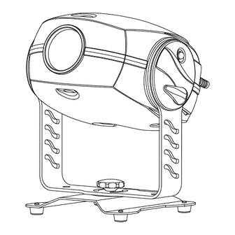
3.Description of the device 1 - Mounting bracket 4 - Bottom cover 2 - Top cover 5 - Adjusting screw 3 - PC lens Rear view of the fixture 6 - Control board 7 - Power cord 8 - Fuse holder 9 - Power switch 10 - Lamp cover 11 -DMX output... -
Page 6: Installation
4.Installation 4.1Fitting/Exchanging the lamp DANGER ! Install the lamp with the device switched off only. Unplug from mains before ! Lamp socket assembly 2 fastening screws To insert the lamp (CDM-SA/T 150W/942): 1.Disconnect the fixture from power and allow it to cool. 2.Loosen the 2 screws „X, Y”... -
Page 7: Changing The Beam Angle
clockwise 1/4-turn at a time until the light is evenly distributed. If the light is brighter around the edge than it is in the center, or if light output is low, the lamp is too far back in the reflector. „Push” the lamp out by turning the screws „A, B, C” counterclockwise 1/4-turn at a time the light is bright and evenly distributed. -
Page 8: Rigging
4.4 Rigging DANGER TO LIFE! Please consider the respective national norms during the installation! The installation must only be carried out by an authorized dealer! The installation of the fixture has to be built and constructed in a way that it can hold 10 times the weight for 1 hour without any harming deformation. - Page 9 For overhead use, always install a safety rope that can hold at least 10 times the weight of the fixture. Pull the safety rope through the mounting bracket and over the trussing system etc. Mounting bracket Adjusting screw Mounting bracket (groundplan): Measurements are in milimetres Floor installation.
-
Page 10: Connection To The Mains
Removable stand: Measurements are in milimetres DANGER TO LIFE! Before taking into operation for the first time,the installation has to be approved by an expert! When installing fixtures side-by-side, avoid illuminating one fixture with another! 4.5 Connection to the mains Verify the power supply settings before applying power! If you wish to change the power supply settings,see the chapter Appendix. -
Page 11: Dmx- 512 Connection, Master/Slave Connection
4.6 DMX- 512 connection, master/slave connection Only use a shielded twisted-pair cable designed for RS-485 and 3-pin XLR-plugs and connectors in order to connect the controller with the fixture or one fixture with another. Occupation of the XLR-connection: DMX - output DMX-input XLR mounting-socket: XLR mounting-plug:... -
Page 12: Dmx Protocol 8-Bit
5.DMX Protocol 8-bit Channel Value Function Type of control Colours Open/white proportional Turquoise proportional proportional Cyan proportional Light green proportional Magenta proportional Light Blue proportional Yellow proportional Green proportional Pink proportional Blue proportional Orange proportional 128-189 Forwards rainbow effect from fast to slow proportional 190-193 No rotation... -
Page 13: Controller Mode
The COLORMIX 150 AT WASH WASH can be operated with a controller in controller mode or without the controller in stand-alone mode. Both modes are described in the texts below. 6.Controller mode The fixtures are individually addressed (001-510) on a data link and connected to the controller.The fixtures respond to the DMX signal from the controller. -
Page 14: Stand - Alone Mode
7. Stand - alone mode The fixtures on a data link are not connected to the controller but can execute pre-set programs which can be different for every fixture.To set the program to be played,see the "Stand-alone setting" ( menu "St.AL."). "Stand-alone operation"... -
Page 15: Functions Of The Control Panel
8. Functions of the control panel The control panel situated on the front side of the base offers several features. You can simply set the DMX address,master/slave mode, read the number of lamp or unit hours, run test, make a reset and also use many functions for setting and service purposes. -
Page 16: Slave Control
occur and the fixtures will not work properly! If the fixture is set as the master and DMX signal is connected to its input,the error massage "MAEr" will appear on its display and the fixture's address will be set to its DMX address in order to respond to DMX signal from the controller. - Page 17 - The number of the hours that the COLORMIX 150 AT WASH has been powered On since the counter was last reset.Press [ ] or [ ] to return to the menu.In order to reset this counter to 0, you have to hold the [ ] and [ ]-button and press the [ ]-button.
-
Page 18: Personality Options
8.4 Personality options These options allow you to modify COLORMIX 150 AT WASH operating behavior. Press [ ] and [ ]buttons to select the desired option and press [ ] to set the value or to see next submenu. - DMX presetting The function makes possible to select DMX- channels settings (if they exist) Channel Mode 1 (default) -
Page 19: Test Sequences
button on the control panel and press [ ] to confirm or [ ] to cancel and return to the menu. - Microphone -sensitivity With this function you can adjust the microphone sensitivity from 1(maximum) to 20(minimum) . Use the [ ] or ] buttons to select the level of the microphone sensitivity and press [ ] to confirm the chosen level or [... -
Page 20: Stand-Alone Setting
8.6 Stand-alone setting This menu offers options for stand-alone mode as a selection of the playing program,programming and modifying current programs. - Music trigger The COLORMIX 150 AT WASH enables the sound control of the running programs via the built-in microphone.Use the [ ] or [ ] buttons to select "On"... -
Page 21: Reset Function
- Editing program This menu item allows you to select a program to edit or create.The COLORMIX 150 AT WASH has one built-in program ("tESt") and the 3 free programs,each up to 99 steps. If the fixture is set as a master ,then you may edit any program in the slaves.You can't edit programs on the slave fixtures from their control panels if the master fixture is switched on and connected to the slaves (editing is possible by the master control panel only). - Page 22 - Lamp adjustment This function can be used when you make the fine adjustment of the lamp.If you select "LAAd" pressing by [ ]- button ,all effects will be canceled,shutter will be opened and the dimmer intensity will be set to maximum.Now you can aim the light at a flat surface (wall) and perform the fine lamp adjustment.
-
Page 23: Error And Information Messages
DMX Calibration protocol: After having calibrated required functions press [ ] to confirm (or [ ] to cancel and return to the menu without reset by the "A.rES." function) and use the "A.rES." function in order to write the calibration value to the memory (EEPROM) and to make a reset in order to check the new adjusted position of the colour wheel. - Page 24 Optical System: - High luminous-efficiency parabolic system and PC lens of diameter 88 mm - 21° or 26° beam angle . Beampath Electronics Built-in microphone for music trigger Master/slave operation Digital serial input DMX-512 3 control channels (8-bit protocol) Rigging Stands directly on the floor with removable stand Mounts horizontally or vertically with mounting bracket Vertical head adjusting range: 135°...
-
Page 25: Maintenance And Cleaning
Temperatures Maximum ambient temperature t : 40° C Maximum housing temperature t (steady state): 75° C Minimum distances Min.distance from flammable surfaces: 0.5m Min.distance to lighted object: 0.8m Weight (net) EU-version:8.5 kg US-version:10 kg Shipping weight EU-version:13.5 kg US-version:15 kg Dimensions (mm) 11. - Page 26 It is absolutely essential that the fixture is kept clean and that dust, dirt and smoke-fluid residues must not build up on or within the fixture. Otherwise, the fixture‘s light-output will be significantly reduced. Regular cleaning will not only ensure the maximum light-output, but will also allow the fixture to function reliably throughout its life. Please use a moist, lint-free cloth.
-
Page 27: Appendix 1 - Menu Map
12. Appendix 1 - Menu map Menu Menu Menu Menu Menu Menu DESCRIPTION Level 1 Level 2 Level 3 Level 4 Level 5 Level 6 A001- dM.Ad. DMX addresss A510 d.Abl. Disable master/slave A001 MASt. Set fixture as a master MA.SL. -
Page 28: Appendix 2 - Changing The Power Supply Settings
13. Appendix 2 - Changing the power supply settings Both the transformer and the ballast must be connected correctly for the local AC voltage and frequency. The wrong settings can cause poor performance or demage of the moving head.The factory settings are printed next to the power switch.
Need help?
Do you have a question about the ColorMix Wash I50 and is the answer not in the manual?
Questions and answers