Table of Contents
Advertisement
Quick Links
Download this manual
See also:
User Manual
Advertisement
Table of Contents

Related Manuals for Gefen EXT-DPKVM-841


Summary of Contents for Gefen EXT-DPKVM-841
- Page 1 ® 8x1 DPKVM Switcher EXT-DPKVM-841 User Manual...
- Page 2 LICENSING This product uses software that is subject to open source licenses, including one or more of the General Public License Version 2 and Version 2.1, Lesser General Public License Version 2.1 and Version 3, BSD, and BSD-style licenses. Distribution and use of this product is subject to the license terms and limitations of liability provided in those licenses.
- Page 3 The Gefen 8x1 DPKVM Switcher Easily switch between eight computers using DisplayPort with the Gefen 8x1 DPKVM Switcher. The rack-mountable Gefen 8x1 DPKVM Switcher offers an economical solution for switching between eight different computers to one display location.
-
Page 4: Operation Notes
OPERATION NOTES READ THESE NOTES BEFORE INSTALLING OR OPERATING THE 8X1 DPKVM SWITCHER • The 8x1 DPKVM Switcher supports Pass-through EDID. The Switcher will use the EDID from the currently active input. • Dual Link resolutions up to 2560 x 1600 are supported. •... - Page 5 FEATURES Features • Switches between eight DisplayPort sources with USB 2.0 and Audio to one display, keyboard, and mouse • Supports resolutions up to 2560 x 1600 • Supports DisplayPort version 1.1a • Green mode (low power consumption when DP source is not present) •...
-
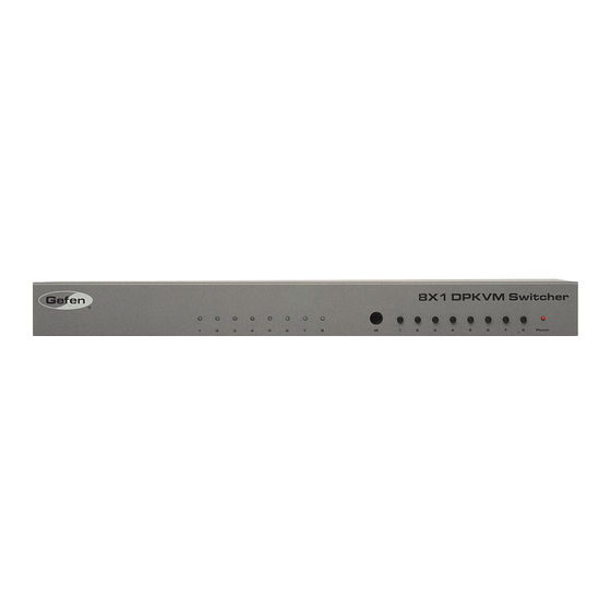
Page 6: Front Panel Layout
FRONT PANEL LAYOUT... -
Page 7: Front Panel Descriptions
FRONT PANEL DESCRIPTIONS Input Indicators (1 - 8) Each of these LED indicators glows bright blue according to the input selection (see Input Buttons, below) Receives IR signals from the included IR Remote Control Unit. Input Buttons (1 - 8) Pressing each of these buttons selects the desired input source (1 - 8). -
Page 8: Back Panel Layout
BACK PANEL LAYOUT... -
Page 9: Back Panel Descriptions
BACK PANEL DESCRIPTIONS 5V DC Connect the included 5V DC locking power supply to this receptacle. In 1 - In 8 Each of these ports will accept a standard DisplayPort source device. Ext IR Connect an IR extender cable to this port. USB Out (1 - 2) Connect USB devices (e.g. -
Page 10: Ir Remote Control Unit
IR REMOTE CONTROL UNIT Layout and Description Activity Indicator This LED will be activated momentarily each time a button is pressed. Source Selection Buttons (1 - 8) These buttons are used to select which source is routed to a monitor. NOTE: An Activity Indictor that flashes quickly while holding down any one of the eight buttons indicates a low battery. - Page 11 IR REMOTE CONTROL UNIT Installing the Battery Remove the battery cover on the back of the IR Remote Control Unit. Insert the included battery into the open battery slot. The positive (+) side of the battery should be facing up. Replace the battery cover.
- Page 12 IR REMOTE CONTROL UNIT Setting the IR Channel In the event that IR commands from other remote controls interfere with the supplied IR Remote Control unit, changing the IR Remote Control’s IR channel will fix the problem. The IR Remote Control unit has a bank of DIP switches used for setting the IR channel.
-
Page 13: Connecting The 8X1 Dpkvm Switcher
OPTIONAL: To extend the range of the IR control, connect an IR Extender (Gefen part no. EXT-RMT-EXTIR) to the back of the Switcher. Connect the included 5V locking power supply to the power receptacle on the 8x1 DPKVM Switcher Connect the opposite end of the power supply to an open wall socket power source. -
Page 14: Operating The 8X1 Dpkvm Switcher
OPERATING THE 8X1 DPKVM SWITCHER Front Panel Buttons and LED Indicators The front panel of the 8x1 DPKVM Switcher has a set of eight (8) LED indicators, displaying which input (source) is being displayed. Each of these LED indicators corresponds to one of the push-buttons on the front panel. Switching sources using the front-panel buttons Example: Switch to input 5 using the front-panel buttons: Press button 5 on the front panel of the 8x1 DPKVM Switcher. - Page 15 OPERATING THE 8X1 DPKVM SWITCHER Switching sources using RS-232 Configure the Switch for use with RS-232 (see page 14 for details). Example: Switch to input 4 using RS-232 Use the command r 4 to route the Switcher to Input 4. See page 15 for important information on RS-232 commands.
-
Page 16: Serial Port Settings
RS-232 CONTROL Only pins 2 (Receive), 3 (Transmit), and 5 (Ground) are used for communication. A null-modem adapter should not be used with this product. 5 4 3 2 1 1 2 3 4 5 9 8 7 6 6 7 8 9 Only Pins 2 (RX), 3 (TX), and 5 (Ground) are used on the RS-232 serial interface Serial Port Settings Bits per second .................... - Page 17 RS-232 COMMANDS Command Syntax All RS-232 commands are case-sensitive and must be entered in lowercase. Each command must be preceded by the ‘#’ character. A carriage return must also be appended to every command. Example: #set_http_port 80[CR] IP Configuration Command Description #get_pass Prompts for the Telnet password...
- Page 18 RS-232 COMMANDS #GET_USER_NAME Command The #GET_USER_NAME command prompts for the Telnet username. Syntax: #get_user_name Parameters: None #IPCONFIG Command The #IPCONFIG command displays all TCP/IP settings. Syntax: #ipconfig Parameters: None #RSTIP Command The #RSTIP command resets the IP configuration to the default settings. Syntax: #rstip Parameters:...
- Page 19 RS-232 COMMANDS #SET_HTTP_PORT Command The #SET_HTTP_PORT command sets the Web server listening port. Syntax: #set_http_port param1 Parameters: Port [0 - 255] param1 #SET_PASS Command The #SET_PASS command sets Telnet password. Syntax: #set_pass param1 Parameters: param1 String Notes: The maximum length of the password string is 20 characters. #SET_TELNET_PORT Command The #SET_TELNET_PORT command sets the Telnet server listening port.
- Page 20 RS-232 COMMANDS #SET_USER_NAME Command The #SET_USER_NAME command sets the Telnet user name. Syntax: #set_user_name param1 Parameters: String param1 Notes: The maximum length of the username string is 20 characters. #SGATEWAY Command Specifies the new IP gateway. Dot-decimal notation must be used when specify- ing the IP address.
- Page 21 RS-232 COMMANDS #SIPADD Command The #SIPADD command specifies a new IP address. Dot-decimal notation must be used when specifying the IP address. A reboot is required after the new IP address is set. Syntax: #sipadd param1.param2.param3.param4 Parameters: param1 IP address [0 - 255] param2 IP address...
- Page 22 RS-232 COMMANDS #USE_TELNET_PASS Command The #USE_TELNET_PASS command enables / disabled the use of a Telnet password during the login process. Syntax: #use_telnet_pass param1 Parameters: param1 State [0 - 1] Value Meaning Disable password Enable password General Commands Command Description #activebolo Activates the bootloader #fadefault Resets the Switcher to the default routing state...
- Page 23 RS-232 COMMANDS #FADEFAULT Function The #FADEFAULT function will reset the Switcher to the default routing settings. Syntax: #fadefault Parameters: None #IRRMTADD Command The #IRRMTADD sets the IR channel. The IR channel for the Switcher and the IR Remote Control Unit must be the same. Syntax: #irrmtadd param1 Parameters:...
- Page 24 RS-232 COMMANDS #LOCKPOWER Command The #LOCKPOWER enables/disables the power lock state. Enabling this feature will store the 5V status for each input prior to shutting the unit down. This preserves the 5V state when the unit is restarted. Syntax: #lockpower param1 Parameters: param1 State...
- Page 25 RS-232 COMMANDS Routing Commands The following command does not require the ‘#’ character. A carriage return must be added to the end of the command. Command Description Routing command R Command The R command switches to the specified input. Syntax: r param1 Parameters: param1...
-
Page 26: Telnet Control
TELNET CONTROL The Gefen 8x1 DPKVM Switcher supports Telnet for controlling the Switcher over a network. To access this feature, an IP address, subnet, gateway, and port numbers need to be set correctly. Consult the network administrator to obtain the proper IP address and settings for this product to properly communicate with the Switcher over a network. - Page 27 TELNET CONTROL Use the #sipadd command to set the IP address for the Switcher. Check with a network administrator to obtain an available address, if necessary. DHCP is not supported by this Switcher. #sipadd 192.168.2.234 New IP set to: 192.168.2.234 After setting the IP address, power-cycle the Switcher for the changes to take effect.
-
Page 28: Firmware Update
FIRMWARE UPDATE Firmware Update Procedure Any terminal emulation program can be used to perform the upgrade process. The instructions below is outlined for Windows® HyperTerminal. Connect an RS-232 cable between the Switcher and the computer running the terminal program. Verify the correct serial port settings (see page 14). Type the #activebolo command then press the [ENTER] key. -
Page 29: Rack Ear Installation
RACK EAR INSTALLATION Installing the Rack Ears Rack mount ears are provided for installation of this unit into a 1U rack mount space. Locate the side screws on the unit. Remove the front 2 screws that are located closest to the front of the unit. Using the removed screws, screw the rack mounting bracket into the unit. -
Page 30: Specifications
SPECIFICATIONS Maximum Pixel Clock................360 MHz Video Input Connectors............(8) DisplayPort, female Video Output Connector............(1) DisplayPort, female USB Host Connectors..........(8) USB 2.0 Type B, female USB Device Connectors..........(2) USB 2.0 Type A, female Audio Input Connectors..........(8) 3.5 mm mini-stereo jack Audio Output Connector..........(1) 3.5 mm mini-stereo jack IR Extender Connector..........(1) 3.5 mm mini-stereo jack RS-232 Control Connector.............(1) DB-9, female Power Supply..................5V DC, Locking... -
Page 31: Warranty
If equipment fails because of such defects and Gefen is notified within two (2) years from the date of shipment, Gefen will, at its option, repair or replace the equipment, provided that the equipment has not been subjected to mechanical, electrical, or other abuse or modifications.
Need help?
Do you have a question about the EXT-DPKVM-841 and is the answer not in the manual?
Questions and answers