Lenovo ThinkCentre M32 Hardware Maintenance Manual
Hide thumbs
Also See for ThinkCentre M32:
- Hardware maintenance manual (96 pages) ,
- User manual (98 pages) ,
- User manual (96 pages)
Table of Contents
Advertisement
Advertisement
Table of Contents
Troubleshooting

Related Manuals for Lenovo ThinkCentre M32


Summary of Contents for Lenovo ThinkCentre M32
- Page 1 ThinkCentre M32 Hardware Maintenance Manual...
- Page 2 “Safety information” on page 3 and Appendix A “Notices” on page 87. Second Edition (January 2014) © Copyright Lenovo 2013, 2014. LIMITED AND RESTRICTED RIGHTS NOTICE: If data or software are delivered pursuant a General Services Administration “GSA” contract, use, reproduction, or disclosure is subject to restrictions set forth in Contract No.
-
Page 3: Table Of Contents
Power supply problems ... Lenovo Support Web site ..Beep symptoms .... - Page 4 Recovering from a system image failure . . . Index....89 Power management ... . ThinkCentre M32 Hardware Maintenance Manual...
-
Page 5: Chapter 1. About This Manual
This manual is intended only for trained service personnel who are familiar with Lenovo computer products. Before servicing a Lenovo computer product, be sure to read “Important safety information” on page 1. Chapter 7 “Symptom-to-FRU Index” on page 51 and Chapter 10 “Additional service information” on page 81 are not specific to any machine type and are applicable to all ThinkCentre computers. - Page 6 ThinkCentre M32 Hardware Maintenance Manual...
-
Page 7: Chapter 2. Safety Information
• Reinstall all covers correctly before returning the machine to the customer. Electrical safety CAUTION: Electrical current from power, telephone, and communication cables can be hazardous. To avoid personal injury or equipment damage, disconnect the attached power cords, telecommunication © Copyright Lenovo 2013, 2014... - Page 8 • Do not service the following parts with the power on when they are removed from their normal operating places in a machine: – Power supply units – Pumps – Blowers and fans – Motor generators and similar units. (This practice ensures correct grounding of the units.) • If an electrical accident occurs: ThinkCentre M32 Hardware Maintenance Manual...
-
Page 9: Safety Inspection Guide
– Use caution; do not become a victim yourself. – Switch off power. – Send another person to get medical aid. Safety inspection guide The intent of this inspection guide is to assist you in identifying potentially unsafe conditions on these products. -
Page 10: Grounding Requirements
• Brazilian/Portuguese • Chinese (simplified) • Chinese (traditional) • French • German • Hebrew • Italian • Korean • Spanish DANGER Electrical current from power, telephone and communication cables is hazardous. To avoid a shock hazard: ThinkCentre M32 Hardware Maintenance Manual... - Page 11 • Do not connect or disconnect any cables or perform installation, maintenance, or reconfiguration of this product during an electrical storm. • Connect all power cords to a properly wired and grounded electrical outlet. • Connect to properly wired outlets any equipment that will be attached to this product. •...
- Page 12 The device also might have more than one power cord. To remove all electrical current from the device, ensure that all power cords are disconnected from the power source. ThinkCentre M32 Hardware Maintenance Manual...
- Page 13 Chapter 2 Safety information...
- Page 14 ≥18 kg (37 lbs) ≥32 kg (70.5 lbs) ≥55 kg (121.2 lbs) PERIGO A corrente elétrica proveniente de cabos de alimentação, de telefone e de comunicações é perigosa. ThinkCentre M32 Hardware Maintenance Manual...
- Page 15 Para evitar risco de choque elétrico: • Não conecte nem desconecte nenhum cabo ou execute instalação, manutenção ou reconfiguração deste produto durante uma tempestade com raios. • Conecte todos os cabos de alimentação a tomadas elétricas corretamente instaladas e aterradas. •...
- Page 16 O dispositivo também pode ter mais de um cabo de alimentação. Para remover toda a corrente elétrica do dispositivo, assegure que todos os cabos de alimentação estejam desconectados da fonte de alimentação. ThinkCentre M32 Hardware Maintenance Manual...
- Page 17 Chapter 2 Safety information...
- Page 18 ThinkCentre M32 Hardware Maintenance Manual...
- Page 19 Chapter 2 Safety information...
- Page 20 • l'exposer à des températures supérieures à 100°C, • chercher à la réparer ou à la démonter. Ne pas mettre la pile à la poubelle. Pour la mise au rebut, se reporter à la réglementation en vigueur. ThinkCentre M32 Hardware Maintenance Manual...
- Page 21 ATTENTION: Si des produits à laser (tels que des unités de CD-ROM, de DVD-ROM, des unités à fibres optiques, ou des émetteurs) sont installés, prenez connaissance des informations suivantes : • Ne retirez pas le carter. En ouvrant l'unité de CD-ROM ou de DVD-ROM, vous vous exposez au rayonnement dangereux du laser.
- Page 22 Lithiumbatterie, dieses nur durch ein Modul desselben Typs und von demselben Hersteller ersetzen. Die Batterie enthält Lithium und kann bei unsachgemäßer Verwendung, Handhabung oder Entsorgung explodieren. Die Batterie nicht: • mit Wasser in Berührung bringen. ThinkCentre M32 Hardware Maintenance Manual...
- Page 23 • über 100 C erhitzen. • reparieren oder zerlegen. Die örtlichen Bestimmungen für die Entsorgung von Sondermüll beachten. ACHTUNG: Bei der Installation von Lasergeräten (wie CD-ROM-Laufwerken, DVD- aufwerken, Einheiten mit Lichtwellenleitertechnik oder Sendern) Folgendes beachten: • Die Abdeckungen nicht entfernen. Durch Entfernen der Abdeckungen des Lasergeräts können gefährliche Laserstrahlungen freigesetzt werden.
- Page 24 ThinkCentre M32 Hardware Maintenance Manual...
- Page 25 Chapter 2 Safety information...
- Page 26 • Riscaldarla ad una temperatura superiore ai 100 gradi C (212 gradi F) • Smontarla, ricaricarla o tentare di ripararla Le batterie usate vanno smaltite in accordo alla normativa in vigore (DPR 915/82 e successive disposizioni e disposizioni locali). ThinkCentre M32 Hardware Maintenance Manual...
- Page 27 ATTENZIONE: Quando vengono installati prodotti laser (quali CD-ROM, unità DVD-ROM, unità a fibre ottiche o trasmittenti), tener presente quanto segue: • Non rimuovere gli sportelli. L'apertura di un'unità laser può determinare l'esposizione a radiazioni laser pericolose. All'interno dell'unità non vi sono parti su cui effettuare l'assistenza tecnica. •...
- Page 28 ThinkCentre M32 Hardware Maintenance Manual...
- Page 29 PELIGRO La corriente eléctrica procedente de cables de alimentación, teléfonos y cables de comunicación puede ser peligrosa. Para evitar el riesgo de descarga eléctrica: • No conecte ni desconecte los cables ni realice ninguna tarea de instalación, mantenimiento o reconfiguración de este producto durante una tormenta eléctrica. •...
- Page 30 • No quite las cubiertas. Si quita las cubiertas del producto láser, podría quedar expuesto a radiación láser peligrosa. Dentro del dispositivo no existe ninguna pieza que requiera servicio técnico. • Si usa controles o ajustes o realiza procedimientos que no sean los especificados aquí, podría exponerse a radiaciones peligrosas. PELIGRO ThinkCentre M32 Hardware Maintenance Manual...
- Page 31 Algunos productos láser tienen incorporado un diodo láser de clase 3A o clase 3B. Tenga en cuenta lo siguiente: Cuando se abre, queda expuesto a radiación láser. No mire directamente al rayo láser, ni siquiera con instrumentos ópticos, y evite exponerse directamente al rayo láser. ≥18 kg ≥32 kg ≥55 kg...
- Page 32 ThinkCentre M32 Hardware Maintenance Manual...
-
Page 33: Chapter 3. General Information
The ac power adapter input voltage: 100 to 240 V ac Input frequency range: 50 or 60 Hz Lenovo Support Web site Technical support information is available on the Lenovo Support Web site at: http://www.lenovo.com/support This Web site is updated with the latest support information such as the following: •... - Page 34 ThinkCentre M32 Hardware Maintenance Manual...
-
Page 35: Chapter 4. General Checkout
– Has this configuration ever worked? – If it has been working, what changes were made prior to it failing? – Is this the original reported failure? • Diagnostics version – Type and version level © Copyright Lenovo 2013, 2014... - Page 36 7. Have the same configuration options set in the system 8. Have the same setup for the operating system control files Comparing the configuration and software set-up between “working and non-working” systems will often lead to problem resolution. ThinkCentre M32 Hardware Maintenance Manual...
-
Page 37: Chapter 5. Troubleshooting And Diagnostics
Chapter 5. Troubleshooting and diagnostics This chapter provides information about diagnosing and troubleshooting computer problems. If your computer problem is not described here, see “Lenovo Support Web site” on page 29 for additional troubleshooting resources. Basic troubleshooting The following table provides information to help you troubleshoot your computer problems. -
Page 38: Troubleshooting Procedure
• If the diagnostic program detects a hardware failure, contact the Lenovo Customer Support Center. See “Lenovo Support Web site” on page 29 for more information. • If you are unable to run the diagnostic program, contact the Lenovo Customer Support Center. See “Lenovo Support Web site” on page 29 for more information. -
Page 39: Audio Problems
SoundBlaster Pro or SoundBlaster emulation. • Verify that the audio device drivers are correctly installed. See Microsoft Windows help system for more information. If you need technical assistance, see “Lenovo Support Web site” on page 29. Chapter 5 Troubleshooting and diagnostics... -
Page 40: Intermittent Problems
Refer to the documentation that comes with the application or game for instructions on setting sound-card settings. • If you need technical assistance, see “Lenovo Support Web site” on page 29. Intermittent problems Symptom: A problem occurs only occasionally and is difficult to repeat. - Page 41 4. Double-click USB Enhanced Performance Keyboard. The USB Enhanced Performance Keyboard Customization program starts. If these actions do not correct the problem, have the computer and keyboard serviced. See “Lenovo Support Web site” on page 29 for details. The mouse or pointing device does not work Symptom: The mouse or pointing device does not work.
-
Page 42: Monitor Problems
Wrong characters appear on the screen Symptom: Wrong characters appear on the screen. Action: Have the computer serviced. For details, see “Lenovo Support Web site” on page 29. The monitor works when you turn on the computer, but goes blank after some period... - Page 43 Settings. Then click the Monitor tab and select a new refresh rate. • See your operating system documentation or help for further information on monitor settings. If these actions do not correct the problem, your monitor might need service. See “Lenovo Support Web site” on page 29 for details.
-
Page 44: Ethernet Problems
If these actions do not correct the problem, your monitor might need service. See “Lenovo Support Web site” on page 29 for details. Ethernet problems For Ethernet problems, select your symptom from the following list: • “Your computer cannot connect to the network” on page 40 •... -
Page 45: Option Problems
• Ensure that the switch is 802.3ab-compliant (gigabit over copper). Option problems If your computer is equipped with Lenovo hardware options, use this information to diagnose problems with Lenovo hardware options that do not have their own troubleshooting information. Select your symptom from the following list: •... -
Page 46: Printer Problems
45. If the problem persists, run the tests described in the documentation that comes with your printer. If you cannot correct the problem, have the computer serviced. See “Lenovo Support Web site” on page 29. Serial connector problems Use this information to troubleshoot the serial connector and devices attached to the serial connector. -
Page 47: Usb Problems
• If you are unable to resolve the problem through other methods, uninstall the software program and reinstall it. If these actions do not correct the problem, you might need technical assistance. Contact your software manufacturer or see “Lenovo Support Web site” on page 29 for details. USB problems Symptom: The USB connectors cannot be accessed. -
Page 48: Diagnostics
• Reset the device by detaching and reattaching the USB connector. If the USB device came with its own diagnostics, run those diagnostics against the USB device. If you need technical assistance, see “Lenovo Support Web site” on page 29. Diagnostics The diagnostic program is used to test hardware components of your computer. -
Page 49: Chapter 6. Using The Setup Utility Program
Using passwords By using the Setup Utility program, you can set passwords to prevent unauthorized access to your computer and data. The following types of passwords are available: • Power-On Password © Copyright Lenovo 2013, 2014... -
Page 50: Password Considerations
• If the Hard Disk Password is forgotten, there is no way to reset the password or recover data from the hard disk drive. Setting, changing, and deleting a password To set, change, or delete a password, do the following: 1. Start the Setup Utility program. See “Starting the Setup Utility program” on page 45. ThinkCentre M32 Hardware Maintenance Manual... -
Page 51: Erasing Lost Or Forgotten Passwords (Clearing Cmos)
2. From the Setup Utility program main menu, select Security. 3. Depending on the password type, select Set Power-On Password, Set Administrator Password, or Hard Disk Password. 4. Follow the instructions on the right side of the screen to set, change, or delete a password. Note: A password can be any combination of up to 64 alphabetic and numeric characters. -
Page 52: Selecting A Startup Device
49. Enabling ErP LPS compliance mode Lenovo computers meet the eco-design requirements of the ErP Lot 3 regulation. For more information, go http://www.lenovo.com/ecodeclaration You can enable the energy-related products directive (ErP) lowest power state (LPS) compliance mode in the Setup Utility program to reduce the consumption of electricity when your computer is in sleep or off mode. -
Page 53: Changing The Bios Settings Before Installing A New Operating System
• Pressing the power button • Enabling the wake up on alarm feature The wake up on alarm feature enables your computer to wake up at a set time. To enable the wake up on alarm feature, do the following: 1. - Page 54 ThinkCentre M32 Hardware Maintenance Manual...
-
Page 55: Chapter 7. Symptom-To-Fru Index
Check the power cord for continuity. Power cord Check the power-on switch for continuity. Power-on switch Beep symptoms Beep symptoms are tones or a series of tones separated by pauses (intervals without sound) during POST. © Copyright Lenovo 2013, 2014... -
Page 56: Post Error Codes
Press F10 to exit. 0662 This error message is displayed when Configuration change has occurred a floppy drive change has been made. Press F10 to exit. ThinkCentre M32 Hardware Maintenance Manual... -
Page 57: Miscellaneous Error Conditions
Error code POST error message Description/Action 1820 More than one external fingerprint If more than one external fingerprint reader are attached. Power off and reader are connected to a computer, remove all but the reader that you set this error message will be displayed up within your main operating system. - Page 58 RPL computer does not RPL from server 1. Check startup sequence. 2. Check the network adapter LED status. Serial or parallel port device failure (system board port) 1. External Device Self-Test OK? 2. External Device 3. Cable 4. System Board ThinkCentre M32 Hardware Maintenance Manual...
-
Page 59: Undetermined Problems
Message/Symptom FRU/Action Serial or parallel port device failure (adapter port) 1. External Device Self-Test OK? 2. External Device 3. Cable 4. Alternate Adapter 5. System Board 1. Keyboard Some or all keys on the keyboard do not work 2. Keyboard Cable 3. - Page 60 ThinkCentre M32 Hardware Maintenance Manual...
-
Page 61: Chapter 8. Locations
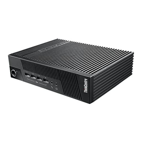
The following figure shows the locations of the connectors, controls, and indicators on the front of your computer. Figure 1. Front connector, control, and indicator locations Power button Power indicator Hard disk drive activity indicator USB 2.0 connectors (4) Microphone connector Headphone connector © Copyright Lenovo 2013, 2014... -
Page 62: Locating Connectors On The Rear Of Your Computer
PS/2 keyboard connector Used to attach a keyboard that uses a PS/2 keyboard connector. PS/2 mouse connector Used to attach a mouse, a trackball, or other pointing devices that use a PS/2 mouse connector. ThinkCentre M32 Hardware Maintenance Manual... -
Page 63: Locating Major Frus And Crus
Connector Description Parallel connector Used to attach a parallel printer or other devices that use a 25-pin parallel connector. Serial connector Used to attach an external modem, a serial printer, or other devices that use a 9-pin serial connector. USB 2.0 connector Used to attach a device that requires a USB 2.0 connection, such as a keyboard, a mouse, a scanner, a printer, or a personal digital assistant (PDA). - Page 64 ThinkCentre M32 Hardware Maintenance Manual...
-
Page 65: Looking Up Fru Information
Power button Heat sink 1 ac power adapter Heat sink 2 Memory module Microprocessor Keyboard Mouse Looking up FRU information For detailed FRU information, such as the FRU part numbers and supported computer models, go to: http:/www.lenovo.com/serviceparts-lookup Chapter 8 Locations... -
Page 66: Locating Parts On The System Board
The following figure shows the locations of the parts and connectors on the system board. Figure 4. Locations of the parts and connectors on the system board Battery Clear CMOS (Complementary Metal Oxide Semiconductor) /Recovery jumper Microprocessor SATA DOM card slot Power button Memory slot ThinkCentre M32 Hardware Maintenance Manual... -
Page 67: Chapter 9. Replacing Frus
Notes: 1. Use only computer parts provided by Lenovo. 2. When installing or replacing an option, use the appropriate instructions in this section along with the instructions that come with the option. - Page 68 Figure 5. Connecting the ac power adapter To remove the ac power adapter, do the following: 1. Turn off the computer and disconnect all power cords from electrical outlets. ThinkCentre M32 Hardware Maintenance Manual...
-
Page 69: Installing Or Removing The Vertical Stand
2. Remove the power cord from the ac power adapter cable loop at the rear of the computer and then disconnect the ac power adapter from the computer. Figure 6. Disconnecting the ac power adapter Installing or removing the vertical stand Attention: Do not open your computer or attempt any repair before reading and understanding the “Important safety information”... - Page 70 2. Align the rear of the computer with the rear of the vertical stand and position the computer on the vertical stand as shown. Figure 7. Installing the vertical stand To remove the vertical stand, do the following: 1. Turn off the computer and disconnect all power cords from electrical outlets. ThinkCentre M32 Hardware Maintenance Manual...
-
Page 71: Removing The Computer Cover
2. Lift the computer to remove it from the vertical stand. Figure 8. Removing the computer from the vertical stand Removing the computer cover This section provides instructions on how to remove the computer cover. CAUTION: Before you open the computer cover, turn off the computer and wait several minutes until the computer is cool. - Page 72 2. Remove the two screws that secure the computer cover. Figure 9. Removing the screws that secure the computer cover ThinkCentre M32 Hardware Maintenance Manual...
-
Page 73: Replacing The Dom Card
3. Slide the computer cover to the front of the computer a small amount. Then, lift the computer cover to remove it from the computer. Figure 10. Removing the computer cover Replacing the DOM card Attention: Do not open your computer or attempt any repair before reading and understanding the “Important safety information”... - Page 74 Figure 12. Removing the DOM card 6. Touch the static-protective package that contains the new DOM card to any unpainted surface on the outside of the computer. Then, take the new DOM card out of the package. ThinkCentre M32 Hardware Maintenance Manual...
-
Page 75: Replacing The Memory Module
7. Align the notch on the new DOM card with the key in the DOM card slot and then insert the new DOM card into the DOM card slot. Ensure that the DOM card is secured firmly in the DOM card slot and does not move easily. - Page 76 Figure 16. Installing the memory module What to do next: • To work with another piece of hardware, go to the appropriate section. • To complete the installation or replacement, go to “Completing the parts replacement” on page 77. ThinkCentre M32 Hardware Maintenance Manual...
-
Page 77: Replacing The Battery
Replacing the battery Attention: Do not open your computer or attempt any repair before reading and understanding the “Important safety information” on page 1. This section provides instructions on how to replace the battery. Your computer has a special type of memory that maintains the date, time, and settings for built-in features, such as parallel-port assignments (configuration). -
Page 78: Replacing The System Board
6. Remove the five screws that secure the system board by following the sequence shown in the following illustration. Then, carefully pivot the failing system board upward to remove it out of the chassis. Note: Carefully handle the system board by its edges. Figure 19. Removing the system board ThinkCentre M32 Hardware Maintenance Manual... - Page 79 7. Note the orientation of the new system board and install it into the chassis. Ensure that the five screw holes in the new system board are aligned with the corresponding mounting studs on the chassis. Note: Carefully handle the system board by its edges. Figure 20.
-
Page 80: Replacing The Keyboard
This section provides instructions on how to replace the mouse. To replace the mouse, do the following: 1. Turn off the computer and disconnect all power cords from electrical outlets. 2. Disconnect the old mouse cable from the computer. ThinkCentre M32 Hardware Maintenance Manual... -
Page 81: Completing The Parts Replacement
3. Connect a new mouse to the appropriate connector on the computer. Your mouse might be connected to a PS/2 mouse connector or a USB connector . Depending on where you want to connect your mouse, see “Locating connectors, controls, and indicators on the front of your computer” on page 57 or “Locating connectors on the rear of your computer”... - Page 82 2. Position the computer cover on the chassis and then push the cover to the rear of the computer until it snaps into position. Figure 24. Installing the computer cover ThinkCentre M32 Hardware Maintenance Manual...
-
Page 83: Obtaining Device Drivers
6. To update the configuration, see Chapter 6 “Using the Setup Utility program” on page 45. Note: In most areas of the world, Lenovo requires the return of the defective Field Replaceable Units (FRUs). Information about this will come with the new FRUs or will come a few days after you receive the new FRUs. - Page 84 ThinkCentre M32 Hardware Maintenance Manual...
-
Page 85: Chapter 10. Additional Service Information
– Start the Setup Utility. – Select Standard CMOS Features. • Sources for obtaining the latest level BIOS available 1. Lenovo support web site: http://www.lenovo.com/support/ 2. Lenovo Customer Support Center 3. Levels 1 and 2 Support To update (flash) the BIOS, see “Flash update procedures” on page 81. -
Page 86: Updating (Flashing) The Bios From A Disc
Note: You can download a self-starting bootable disc image (known as an ISO image) with the system program updates to create a system-program-update disc. Go to http://www.lenovo.com/support. To update (flash) the BIOS from a disc on the Windows 8 (64-bit) operating system, do the following: 1. -
Page 87: Updating (Flashing) The Bios From Your Operating System
Updating (flashing) the BIOS from your operating system Note: Because Lenovo makes constant improvements to its Web sites, the Web page contents are subject to change without notice, including the contents referenced in the following procedure. To update (flash) the BIOS from your operating system, do the following: 1. -
Page 88: Recovering From A System Image Failure
Recovering from a system image failure To recover from a system image failure, contact the Lenovo Customer Support Center. The most up-to-date telephone list for the Customer Support Center is always available at: http://www.lenovo.com/support/phone The following services are available: • Problem determination - Trained service personnel are available to assist you with determining a hardware problem and deciding what action is necessary to fix the problem. - Page 89 Note: If the settings are unavailable, click Change settings that are currently unavailable. 5. Click Save changes. Chapter 10 Additional service information...
- Page 90 ThinkCentre M32 Hardware Maintenance Manual...
-
Page 91: Appendix A. Notices
Lenovo representative for information on the products and services currently available in your area. Any reference to a Lenovo product, program, or service is not intended to state or imply that only that Lenovo product, program, or service may be used. Any functionally equivalent product, program, or service that does not infringe any Lenovo intellectual property right may be used instead. -
Page 92: Television Output Notice
Macrovision Corporation. Reverse engineering or disassembly is prohibited. European conformance CE mark Trademarks The following terms are trademarks of Lenovo in the United States, other countries, or both: Lenovo The Lenovo logo The ThinkCentre logo ThinkCentre Microsoft and Windows are trademarks of the Microsoft group of companies. -
Page 93: Index
Lenovo Thin Client Manager rear Lenovo Thin Client Manager, LTM connectors, controls, indicators locating components front looking up part numbers 1, 57, 61 considerations, passwords completing the installation CRUs (Customer Replaceable Units), returning defective... - Page 94 Setup Utility program, starting Setup Utility, exiting starting the Setup Utility program startup device sequence, changing temporary, selecting static-sensitive devices, handling support web site support support, web site system board connectors locating parts memory module system board, replacing ThinkCentre M32 Hardware Maintenance Manual...
Need help?
Do you have a question about the ThinkCentre M32 and is the answer not in the manual?
Questions and answers