Lenovo ThinkCentre M720t User Manual And Hardware Maintenance Manual
Hide thumbs
Also See for ThinkCentre M720t:
- User manual and hardware maintenance manual (86 pages) ,
- User manual and hardware maintenance manual (86 pages)

Related Manuals for Lenovo ThinkCentre M720t


Summary of Contents for Lenovo ThinkCentre M720t
- Page 1 ThinkCentre M720t User Guide and Hardware Maintenance Manual Energy Star Machine Types: 10SQ, 10SR, 10SS, 10TQ, 10U4, and 10U5...
- Page 2 Important Product Information Guide and Appendix A “Notices” on page 77. First Edition (June 2018) © Copyright Lenovo 2018. LIMITED AND RESTRICTED RIGHTS NOTICE: If data or software is delivered pursuant to a General Services Administration “GSA” contract, use, reproduction, or disclosure is subject to restrictions set forth in Contract No. GS-...
-
Page 3: Table Of Contents
Replacing the optical drive bracket ..Appendix B. Trademarks ..79 Replacing the storage drive ..© Copyright Lenovo 2018... - Page 4 ThinkCentre M720t User Guide and Hardware Maintenance Manual...
-
Page 5: Chapter 1. Overview
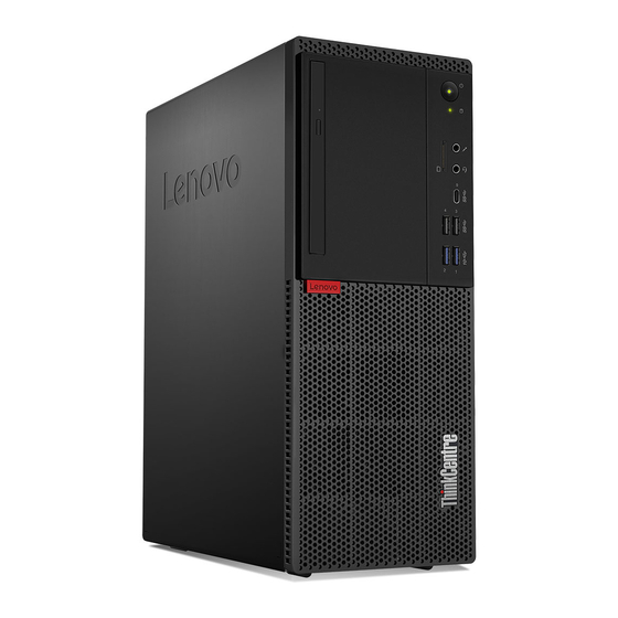
Card reader slot (optional) Power indicator Microphone connector Headset connector Type-C USB 3.1 Gen 1 connector USB 3.1 Gen 1 connectors (2) USB 3.1 Gen 2 connectors (2) Illuminated red dot Optical drive eject/close button (optional) © Copyright Lenovo 2018... - Page 6 Used to connect a USB-compatible device. For optimal data transfer, connect a USB 3.1 Gen 2 device to a USB 3.1 Gen 2 connector instead of a USB 3.1 Gen 1 or USB 2.0 connector. Illuminated red dot This indicator is on when the computer is on. ThinkCentre M720t User Guide and Hardware Maintenance Manual...
-
Page 7: Rear View
Rear view Note: Your computer model might look slightly different from the illustration. Figure 2. Rear view Audio line-out connector VGA-out connector ® DisplayPort 1.2 out connectors (2) USB 2.0 connector USB 2.0 connectors (3) Serial connector Ethernet connector PS/2 keyboard and mouse connectors (optional) Smart cable clip slots (2) (optional) Serial connector (optional) PCI Express card area... - Page 8 Used to connect a device that requires a USB 2.0 connection. Note: The USB 2.0 connector supports the smart power on feature. If you connect a Lenovo-recommended USB 1.1 keyboard to this connector, you can power on the computer or wake it up from S4 hibernation mode by pressing Alt+P on the keyboard.
-
Page 9: System Board
Used to secure a Kensington-style cable lock. Power cord connector Used to connect the power cord to your computer for power supply. System board Note: See “Front view” and “Rear view” for additional component descriptions. Figure 3. System board 4-pin power connector Microprocessor fan connector Power button connector Internal speaker connector... -
Page 10: Machine Type And Model Label
Keyboard and mouse connector Machine type and model label The machine type and model label identifies the computer. When you contact Lenovo for help, the machine type and model information helps support technicians to identify the computer and provide faster service. -
Page 11: Chapter 2. Specifications
• USB connectors (USB 2.0, USB 3.1, and Type-C USB 3.1) • VGA-out connector Expansion • Card reader (optional) • Memory slots • M.2 solid-state drive slot • Optical drive (optional) • PCI Express x1 card slots © Copyright Lenovo 2018... - Page 12 Physical dimensions • Width: 150 mm (5.9 inches) • Height: 360 mm (14.2 inches) • Depth: 270.5 mm (10.6 inches) Weight (without the package) Maximum configuration as shipped: 6.9 kg (15.2 lb) ThinkCentre M720t User Guide and Hardware Maintenance Manual...
-
Page 13: Chapter 3. Computer Locks
3. Click Security ➙ Electronic Lock to enable or disable the E-lock. 4. Press F10 or Fn+F10 to save the changes and reboot the computer. Note: Changes do not take effect until the setting is saved and the system is rebooted. © Copyright Lenovo 2018... -
Page 14: Attaching A Kensington-Style Cable Lock
The cable lock also locks the buttons used to open the computer cover. This is the same type of lock used with many notebook computers. You can order such a cable lock directly from Lenovo by searching for Kensington at: http://www.lenovo.com/support Figure 7. - Page 15 Figure 8. Attaching a smart cable clip Chapter 3 Computer locks...
- Page 16 ThinkCentre M720t User Guide and Hardware Maintenance Manual...
-
Page 17: Chapter 4. Replacing Hardware
• When installing or replacing an option, use the appropriate instructions explained in this manual along with the instructions that come with the option. • In most areas of the world, Lenovo requires the return of defective CRUs. Information about this will come with the CRU or will come a few days after the CRU arrives. -
Page 18: Locating Frus (Including Crus)
Locating FRUs (including CRUs) Notes: • Some of the components are optional. • To replace a component that is not in the list below, contact a Lenovo service technician. For a list of Lenovo Support phone numbers, go to: http://www.lenovo.com/support/phone... - Page 19 Figure 9. Locating FRUs Self-service CRUs Optional-service CRUs Non-CRUs Computer cover Wi-Fi card Heat sink and fan assembly Wi-Fi card shield Rear fan Coin-cell battery Memory module Power supply assembly Microprocessor M.2 solid-state drive heat sink E-lock System board M.2 solid-state drive Power button M.2 solid-state drive bracket Optical drive cable...
-
Page 20: Replacing The Keyboard Or Wireless Keyboard
1. Remove your old wireless keyboard. 2. Take out the new wireless keyboard from the package. 3. Open the battery compartment cover, and install two AAA batteries according to the polarity indicators. ThinkCentre M720t User Guide and Hardware Maintenance Manual... -
Page 21: Replacing The Mouse Or Wireless Mouse
Figure 11. Replacing the wireless keyboard 4. Remove the USB dongle from the keyboard compartment or from the wireless mouse compartment and connect it to an available USB connector on the computer. 5. Close the compartment cover. The keyboard is ready for use. Replacing the mouse or wireless mouse Note: The wireless mouse is available only on some models. - Page 22 Figure 13. Opening the battery compartment Figure 14. Taking out the USB dongle ThinkCentre M720t User Guide and Hardware Maintenance Manual...
- Page 23 Figure 15. Connecting the USB dongle to a USB connector Figure 16. Installing the mouse batteries Chapter 4 Replacing hardware...
- Page 24 • Push the power switch to the off position when you are not using the mouse to extend the battery life. • After disconnecting the USB dongle from your computer, store it in the wireless mouse compartment or in the wireless keyboard compartment. ThinkCentre M720t User Guide and Hardware Maintenance Manual...
-
Page 25: Replacing The Power Cord
Replacing the power cord Attention: Do not open your computer or attempt any repairs before reading the Important Product Information Guide. 1. Remove any media from the drives and turn off all connected devices and the computer. 2. Disconnect all power cords from electrical outlets and disconnect all cables that are connected to the computer. -
Page 26: Replacing The Dust Shield
2. Disconnect all power cords from electrical outlets and disconnect all cables that are connected to the computer. 3. Replace the dust shield. Figure 21. Removing the dust shield Figure 22. Installing the dust shield ThinkCentre M720t User Guide and Hardware Maintenance Manual... -
Page 27: Removing The Computer Cover
Removing the computer cover Note: Before you open the computer cover, ensure that the E-lock has been unlocked in the Setup Utility program. See “Computer locks”. Attention: Do not open your computer or attempt any repairs before reading the Important Product Information Guide. -
Page 28: Replacing The Optical Drive
1. Remove the computer cover. See “Removing the computer cover” on page 23. 2. Remove the front bezel. See “Replacing the front bezel” on page 23. 3. Disconnect the signal and power connectors from the optical drive. 4. Replace the optical drive. ThinkCentre M720t User Guide and Hardware Maintenance Manual... -
Page 29: Replacing The Optical Drive Bracket
Figure 26. Removing the optical drive Figure 27. Installing the optical drive 5. Connect the signal and power connectors to the new optical drive. 6. Complete the replacement. See “Completing the parts replacement” on page 74. Replacing the optical drive bracket Attention: Do not open your computer or attempt any repairs before reading the Important Product Information Guide. -
Page 30: Replacing The Storage Drive
2. Remove the front bezel. See “Replacing the front bezel” on page 23. 3. Disconnect the signal and power connectors from the storage drive. 4. Refer to the following to replace the 3.5–inch storage drive. • 3.5-inch primary storage drive ThinkCentre M720t User Guide and Hardware Maintenance Manual... - Page 31 Figure 30. Opening the drive bay Figure 31. Removing the 3.5–inch primary storage drive Chapter 4 Replacing hardware...
- Page 32 Figure 32. Installing the 3.5–inch primary storage drive Figure 33. Closing the drive bay • 3.5-inch secondary storage drive ThinkCentre M720t User Guide and Hardware Maintenance Manual...
- Page 33 Figure 34. Opening the drive bay Figure 35. Removing the 3.5–inch secondary storage drive Chapter 4 Replacing hardware...
- Page 34 6. Complete the replacement. See “Completing the parts replacement” on page 74. Replacing the 2.5–inch storage drive 1. Remove the storage converter with the 2.5–inch storage drive. See “Replacing the 3.5–inch storage drive”. 2. Replace the 2.5–inch storage drive in the storage converter. ThinkCentre M720t User Guide and Hardware Maintenance Manual...
-
Page 35: Replacing A Memory Module
Figure 38. Removing the 2.5–inch storage drive from the storage converter Figure 39. Installing the new 2.5–inch storage drive to the storage converter 3. Complete the replacement. See “Completing the parts replacement” on page 74. Replacing a memory module Attention: Do not open your computer or attempt any repairs before reading the Important Product Information Guide. - Page 36 1. Remove the computer cover. See “Removing the computer cover” on page 23. 2. Remove the front bezel. See “Replacing the front bezel” on page 23. 3. Replace a memory module. Figure 41. Opening the drive bay ThinkCentre M720t User Guide and Hardware Maintenance Manual...
- Page 37 Figure 42. Removing the memory module Note: During the installation, ensure that you align the memory module to the slot and press down on both ends until the latches are fully engaged with a click. Figure 43. Installing the memory module Figure 44.
-
Page 38: Replacing A Pci Express Card
• When you install the PCI Express card, press down on the rear end of the card until the latch is engaged with a click. Figure 45. Opening the drive bay ThinkCentre M720t User Guide and Hardware Maintenance Manual... - Page 39 Figure 46. Removing the PCI Express card Figure 47. Installing the PCI Express card Chapter 4 Replacing hardware...
-
Page 40: Replacing The Wi-Fi Card
1. Remove the computer cover. See “Removing the computer cover” on page 23. 2. Remove the front bezel. See “Replacing the front bezel” on page 23. 3. Replace the Wi-Fi card. Figure 49. Opening the drive bay ThinkCentre M720t User Guide and Hardware Maintenance Manual... - Page 41 Figure 50. Removing the Wi-Fi card shield (type 1 and type 2) Figure 51. Disconnecting the Wi-Fi antennas and removing the Wi-Fi card (type 1 and type 2) Figure 52. Installing the Wi-Fi card and connecting the Wi-Fi antennas (type 1 and type 2) Chapter 4 Replacing hardware...
-
Page 42: Replacing The M.2 Solid-State Drive
2. Remove the front bezel. See “Replacing the front bezel” on page 23. 3. Depending on your computer model, refer to one of the following to replace the M.2 solid-state drive. • Type 1 ThinkCentre M720t User Guide and Hardware Maintenance Manual... - Page 43 Figure 55. Opening the drive bay Figure 56. Removing the M.2 solid-state drive heat sink Chapter 4 Replacing hardware...
- Page 44 Figure 57. Unlocking the M.2 solid-state drive clip Figure 58. Removing the M.2 solid-state drive Figure 59. Installing the M.2 solid-state drive ThinkCentre M720t User Guide and Hardware Maintenance Manual...
- Page 45 Figure 60. Locking the M.2 solid-state drive clip Figure 61. Installing the M.2 solid-state drive heat sink Figure 62. Closing the drive bay Chapter 4 Replacing hardware...
- Page 46 • Type 2 Figure 63. Opening the drive bay Figure 64. Removing the M.2 solid-state drive heat sink ThinkCentre M720t User Guide and Hardware Maintenance Manual...
- Page 47 Figure 65. Unlocking the M.2 solid-state drive clip Figure 66. Removing the M.2 solid-state drive Figure 67. Installing the M.2 solid-state drive Chapter 4 Replacing hardware...
- Page 48 Figure 68. Locking the M.2 solid-state drive clip Figure 69. Installing the M.2 solid-state drive heat sink Figure 70. Closing the drive bay ThinkCentre M720t User Guide and Hardware Maintenance Manual...
-
Page 49: Replacing The M.2 Solid-State Drive Bracket
4. Complete the replacement. See “Completing the parts replacement” on page 74. Replacing the M.2 solid-state drive bracket Attention: Do not open your computer or attempt any repairs before reading the Important Product Information Guide. 1. Remove the computer cover. See “Removing the computer cover” on page 23. 2. -
Page 50: Replacing The Power Supply Assembly
1. Remove the computer cover. See “Removing the computer cover” on page 23. 2. Remove the front bezel. See “Replacing the front bezel” on page 23. 3. Disconnect the power supply assembly cables from the system board. 4. Replace the power supply assembly. ThinkCentre M720t User Guide and Hardware Maintenance Manual... - Page 51 Figure 73. Opening the drive bay Figure 74. Removing the power supply assembly Chapter 4 Replacing hardware...
-
Page 52: Replacing The Wi-Fi Antennas
1. Remove the computer cover. See “Removing the computer cover” on page 23. 2. Remove the front bezel. See “Replacing the front bezel” on page 23. 3. Replace the front Wi-Fi antenna. ThinkCentre M720t User Guide and Hardware Maintenance Manual... - Page 53 Figure 77. Removing the front Wi-Fi antenna Figure 78. Installing the front Wi-Fi antenna 4. Complete the replacement. See “Completing the parts replacement” on page 74. Replacing the rear Wi-Fi antenna 1. Remove the computer cover. See “Removing the computer cover” on page 23. 2.
- Page 54 Figure 79. Removing the rear Wi-Fi antenna cover Figure 80. Removing the rear Wi-Fi antenna Figure 81. Installing the rear Wi-Fi antenna ThinkCentre M720t User Guide and Hardware Maintenance Manual...
-
Page 55: Replacing The Internal Speaker
Figure 82. Installing the rear Wi-Fi antenna cover Replacing the internal speaker Attention: Do not open your computer or attempt any repairs before reading the Important Product Information Guide. 1. Remove the computer cover. See “Removing the computer cover” on page 23. 2. - Page 56 Figure 84. Removing the internal speaker Figure 85. Installing the internal speaker ThinkCentre M720t User Guide and Hardware Maintenance Manual...
-
Page 57: Replacing The Front Fan
Figure 86. Closing the drive bay 5. Connect the internal speaker cable to the system board. 6. Complete the replacement. See “Completing the parts replacement” on page 74. Replacing the front fan Attention: Do not open your computer or attempt any repairs before reading the Important Product Information Guide. - Page 58 Figure 88. Removing the front fan Figure 89. Installing the front fan ThinkCentre M720t User Guide and Hardware Maintenance Manual...
-
Page 59: Replacing The Illuminated Red Dot Cable
Figure 90. Closing the drive bay 5. Connect the front fan cable to the system board. 6. Complete the replacement. See “Completing the parts replacement” on page 74. Replacing the illuminated red dot cable Attention: Do not open your computer or attempt any repairs before reading the Important Product Information Guide. - Page 60 Figure 92. Removing the illuminated red dot cable Figure 93. Installing the illuminated red dot cable Figure 94. Closing the drive bay ThinkCentre M720t User Guide and Hardware Maintenance Manual...
-
Page 61: Replacing The Thermal Sensor
5. Connect the new illuminated red dot cable to the system board. 6. Complete the replacement. See “Completing the parts replacement” on page 74. Replacing the thermal sensor Attention: Do not open your computer or attempt any repairs before reading the Important Product Information Guide. -
Page 62: Replacing The Front I/O Bracket
2. Remove the front bezel. See “Replacing the front bezel” on page 23. 3. Disconnect the power button cable and the card reader cable from the system board. 4. Replace the front I/O bracket. ThinkCentre M720t User Guide and Hardware Maintenance Manual... - Page 63 Figure 99. Opening the drive bay Figure 100. Removing the front I/O bracket Chapter 4 Replacing hardware...
-
Page 64: Replacing The Power Button
1. Remove the computer cover. See “Removing the computer cover” on page 23. 2. Remove the front bezel. See “Replacing the front bezel” on page 23. 3. Remove the front I/O bracket. See “Replacing the front I/O bracket” on page 58. ThinkCentre M720t User Guide and Hardware Maintenance Manual... -
Page 65: Replacing The Card Reader Board
4. Replace the power button. Figure 103. Removing the power button Figure 104. Installing the power button 5. Connect the power button cable to the system board. 6. Complete the replacement. See “Completing the parts replacement” on page 74. Replacing the card reader board Attention: Do not open your computer or attempt any repairs before reading the Important Product Information Guide. -
Page 66: Replacing The Heat Sink And Fan Assembly
1. Remove the computer cover. See “Removing the computer cover” on page 23. 2. Remove the front bezel. See “Replacing the front bezel” on page 23. 3. Disconnect the microprocessor fan cable from the system board. 4. Replace the heat sink and fan assembly. ThinkCentre M720t User Guide and Hardware Maintenance Manual... - Page 67 Figure 107. Opening the drive bay Figure 108. Removing the heat sink and fan assembly Chapter 4 Replacing hardware...
-
Page 68: Replacing The Microprocessor
1. Remove the computer cover. See “Removing the computer cover” on page 23. 2. Remove the front bezel. See “Replacing the front bezel” on page 23. ThinkCentre M720t User Guide and Hardware Maintenance Manual... - Page 69 3. Remove the heat sink and fan assembly. See “Replacing the heat sink and fan assembly” on page 62. 4. Replace the microprocessor. Notes: • Your microprocessor and socket might look different from the one illustrated. • Touch only the edges of the microprocessor. Do not touch the gold contacts on the bottom. •...
- Page 70 Figure 113. Pivoting the microprocessor socket upward Figure 114. Removing the microprocessor Figure 115. Installing the microprocessor Figure 116. Pivoting the microprocessor socket downward ThinkCentre M720t User Guide and Hardware Maintenance Manual...
-
Page 71: Replacing The Coin-Cell Battery
Figure 117. Locking the microprocessor socket retainer Figure 118. Closing the drive bay 5. Complete the replacement. See “Completing the parts replacement” on page 74. Replacing the coin-cell battery Attention: Do not open your computer or attempt any repairs before reading the Important Product Information Guide. - Page 72 Figure 119. Opening the drive bay Figure 120. Pressing the metallic tab using a driver Figure 121. Removing the coin-cell battery Figure 122. Placing the coin-cell battery ThinkCentre M720t User Guide and Hardware Maintenance Manual...
-
Page 73: Replacing The E-Lock
Figure 123. Pressing the coin-cell battery downward until it is fully engaged with a click Figure 124. Closing the drive bay 4. Complete the replacement. See “Completing the parts replacement” on page 74. To dispose of the coin-cell battery, refer to the “Lithium coin-cell battery notice” topic in the Safety and Warranty Guide. -
Page 74: Replacing The Cover Presence Switch
1. Remove the computer cover. See “Removing the computer cover” on page 23. 2. Disconnect the cover presence switch cable from the system board. 3. Refer to one of the following to replace the cover presence switch. • For models with E-lock installed: ThinkCentre M720t User Guide and Hardware Maintenance Manual... - Page 75 Figure 127. Removing the cover presence switch Figure 128. Installing the cover presence switch • For models without E-lock installed: Chapter 4 Replacing hardware...
-
Page 76: Replacing The Rear Fan
Attention: Do not open your computer or attempt any repairs before reading the Important Product Information Guide. 1. Remove the computer cover. See “Removing the computer cover” on page 23. 2. Disconnect the rear fan cable from the system board. ThinkCentre M720t User Guide and Hardware Maintenance Manual... -
Page 77: Replacing The System Board
3. Replace the rear fan. Figure 131. Removing the rear fan Figure 132. Installing the rear fan 4. Connect the rear fan cable to the system board. 5. Complete the replacement. See “Completing the parts replacement” on page 74. Replacing the system board Attention: Do not open your computer or attempt any repairs before reading the Important Product Information Guide. -
Page 78: Completing The Parts Replacement
13. Complete the replacement. See “Completing the parts replacement” on page 74. Completing the parts replacement After completing the installation or replacement for all parts, reinstall the computer cover and reconnect the cables. ThinkCentre M720t User Guide and Hardware Maintenance Manual... - Page 79 To reinstall the computer cover and reconnect the cables to your computer, do the following: 1. Ensure that all components have been reassembled correctly and that no tools or loose screws are left inside your computer. 2. Ensure that the cables are routed correctly before reinstalling the computer cover. Keep cables clear of the hinges and sides of the computer chassis to avoid interference when reinstalling the computer cover.
- Page 80 ThinkCentre M720t User Guide and Hardware Maintenance Manual...
-
Page 81: Appendix A. Notices
Lenovo representative for information on the products and services currently available in your area. Any reference to a Lenovo product, program, or service is not intended to state or imply that only that Lenovo product, program, or service may be used. Any functionally equivalent product, program, or service that does not infringe any Lenovo intellectual property right may be used instead. - Page 82 ThinkCentre M720t User Guide and Hardware Maintenance Manual...
-
Page 83: Appendix B. Trademarks
Appendix B. Trademarks The following terms are trademarks of Lenovo in the United States, other countries, or both: Lenovo The Lenovo logo ThinkCentre The ThinkCentre logo DisplayPort is a trademark of the Video Electronics Standards Association. Other company, product, or service names may be trademarks or service marks of others. - Page 84 ThinkCentre M720t User Guide and Hardware Maintenance Manual...
Need help?
Do you have a question about the ThinkCentre M720t and is the answer not in the manual?
Questions and answers