Table of Contents
Advertisement
Quick Links
Advertisement
Table of Contents

Related Manuals for Linkam Scientific Instruments CSS450


Summary of Contents for Linkam Scientific Instruments CSS450
- Page 1 Linkam Scientific Instruments CSS450 Optical Rheology System USER GUIDE...
-
Page 2: Table Of Contents
Connecting the Stage to the Controller .............. 16 Mains Connection..................16 Connecting the Water Cooling Supply / Circulator ........17 Connecting the Liquid Nitrogen Pump for Cryo-CSS450 System ....18 Connecting the LNP95 ................18 Setting up the Linksys32 Software ............20... - Page 3 Appendix 2 : Spare Parts List ............39 Appendix 3 : Declaration of Conformity ..........40 Appendix 4 : Technical Specification ............ 41 CSS450 Stage Technical Specification ............41 CSS450 Controller Technical Specification ........... 41 CSS450 Controller Equipment Ratings ............41 RS232 Computer Interface .................
-
Page 4: Safety Information
Contact Linkam Scientific Instruments Ltd or their appointed distributor immediately. Your warranty may be impaired if Linkam is not informed of any transport damage within 7 working days of delivery. -
Page 5: Handling Liquid Nitrogen
Contactez Linkam Scientific Instruments Ltd ou son distributeur désigné immédiatement. Votre garantie pourrait être réduite si Linkam n'est pas informée de tout dommage causé par le transport dans les 7 jours ouvrables suivant la livraison. -
Page 6: Étiquettes D'avertissement Et Indicateurs
12. Le cordon d'alimentation doit être constitué d'un ensemble de câbles répondant aux caractéristiques nomi- nales et approuvé dans le pays d'utilisation. 13. Si un problème survient, débranchez le cordon d'alimentation de la prise de courant et contactez le support technique de Linkam. -
Page 7: Introduction
All connections must be in place before the CSS450 Shear Controller is switched on. If an LNP95 unit is being used it is important that it is switched on before the CSS450 unit, otherwise the equipment will not function correctly. -
Page 8: Introduction To Css450 Stage
CSS450 System not in use for a long period of time. The CSS450 Shear Stage is made up from two parts, the Lid and Base (see pictures). The stage is designed to fit on most standard upright micro- scopes and has a temperature range from ambient (-50°C for Cryo-CSS450) to 450°C. -
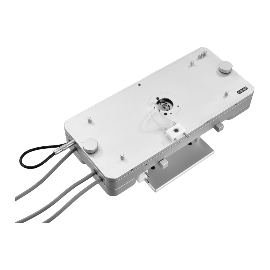
Page 9: Anatomy Of A Css450
Anatomy of a CSS450 When in use, the sample is placed between two highly polished quartz windows that are parallel to within 2mm and each window is in close ther- mal contact with a silver heater. The Base win- dow, located within the lower section of the shear- ing stage, is attached to a metal carrier that can rotate under the control of the Shear Motor. -
Page 10: Accessories
Accessories The accessories for the stage are supplied in an accessories kit (part no: 2053), containing the items in the picture below. Number Part number Part description 3016 Lid Nut (CSS-LN) 3033 Motor Nut 3011 18mm External Window Locking Tool 2912 55mm Window Clamp Tool 3003... -
Page 11: Getting Started
Getting Started When fully unpacked, check for the following items; CSS450 ‘Controller’, a mains power lead, RS232 lead and a CD with Linksys32 software. In a separate dedicated plastic case there will be a complete CSS450 Shearing ‘Stage’ consisting of the Lid, the Base, a flat packed Stand and an accessories kit. -
Page 12: Assembling The Lid And Base
Assembling the Lid and Base 1. Place the Base on the Stand. 2. Place the Lid on top of the Base. Make sure the three holes at the top right hand side corner of the Base are aligned and matched with the three sensor pins on the Lid (1). -
Page 13: Mounting On To A Microscope
Microscope Fixing Plate. The two curved clamps are used to fix the CSS450 to the microscope. To do this; adjust the two positioning screws (2) and thumb screw (3) so that they are showing about 5mm of thread on the inside edge of the Curved Clamps. -
Page 14: Introduction To Css450 System Controller
The CSS450 requires a motor expansion board, which requires the ’motor’ and ’sensor leads to be connected correctly. Any of the stages which use an expansion board will be marked with the same label as the CSS450 expansion board. External Input and Output Sockets There are three 2.5mm jack sockets (6) on the rear of the CSS450 for synchronising or controlling external... -
Page 15: Lnp95 Liquid Nitrogen Pump
Only read the following if the LNP95 Liquid Nitrogen Cooling Pump System is supplied with your system. The LNP95 System uses liquid nitrogen to cool the stage from ambient to -196ºC. The speed of the LNP95 is automatically controlled from 1 to 100 by the CSS450. Note: refer to the LNP95 manual for more information Introduction Please check that all of the following parts have been supplied with the LNP95 System. -
Page 16: Connecting The Stage To The Controller
Connect the Stage to the Controller Connect to mains Connect The CSS450 Controller controls the temperature power CSS450 and the Shear and Gap motors of the stage. Stage Refer to the back of the controller. Connect the supplied RS232 lead from the RS232 socket on the back of the controller to the PC’s serial/Comm... -
Page 17: Connecting The Water Cooling Supply/Circulator
Connecting the Water Cooling Supply/Circulator When the CSS450 is used at temperatures exceed- ing 200°C for a prolonged period of time it will become warm/hot to the touch. To ensure that the stage is always safe to handle, a system of water- cooling is recommended. -
Page 18: Connecting The Liquid Nitrogen Pump For Cryo-Css450 System
Connecting the Liquid Nitrogen Pump for Cryo-CSS450 System Note: this is only appropriate if you have pur- chased the Cryo-CSS450 system. If not then go to the section, “Setting up the Linksys32 Soft- ware”, page 18. A Cryo-CSS450 system adds liquid nitrogen cooling functionality to the CSS450 stage. - Page 19 (O.D. 4mm, I.D. 2mm) can be sourced locally or directly from Linkam. When all the connections have been made, the CSS450 is ready to be used to cool the sample below room temperature to –50°C. The CSS450 Controller will communicate with...
-
Page 20: Setting Up The Linksys32 Software
Setting up the Linksys32 Software Ensure that the RS232 cable is connected between the PC serial RS232 port (Comm port) and the CSS450 controller. Start the Linksys32 software by double clicking on the ‘Linksys32 - Shortcut’ icon on the PC. The temperature Control Status Display will show the message: ‘No Comm Programmer not connected’. -
Page 21: Changing The Comm Port Number
Changing Comm Port Number Go to: Setup > Temperature Controller In the popup window ‘Linksys32 Setup’ make sure ‘TempControl’ is selected. Use PC mouse to select the Comm port (2 to 6) the RS232 cable is connected to, then click the ‘X’ button in the top right hand corner to close the window. -
Page 22: Linksys32 Tool Bar
CSS450 is first connected. Sensor Indicators There are three sensors in the Lid of the CSS450, marked with the letters L, R and Z. L represents the Lid sensor, it is lit green when the Lid is in place. -
Page 23: Loading The Sample
Lid. Unscrew the Lid Nuts and remove the Lid . Place the Lid on the Stand (the picture shows the CSS450 with the Linkam Imaging Station) and place the sample in the middle of the Base win- dow. -
Page 24: Start The Shearing Experiment
Take note of the warning popup window and move the lens clear of the lid. There are two ways to control shearing in the CSS450. The Manual Jog Controls and the Shear Motor Profile table. Using the Shear Motor Profile To use the Shear Motor Profile table, make sure the ‘Use Motor Profile’... - Page 25 Ramp column, then Right clicking and selecting ‘Check Row’ from the drop down list. If a cell contains a value that the CSS450 is not able to execute, then a warning box will appear with a message detailing the possible parameters for that particular cell.
-
Page 26: Start The Profile
‘Stop’ button at any time. Adjusting the Shear Parameters Accessing the Setup Menu: To access the Setup menus for the CSS450. Right click on the Tool bar within the CSS450 control panel. General Setup Motor Profile Time Units - Specify units for each Ramp in the Profile by clicking either ‘Seconds’... -
Page 27: Finish A Shearing Experiment
Lid to avoid damage. Remove the Lid and place it on the Stand (the pictures show the CSS450 with the Linkam Imag- ing Station). Remove the sample and use a soft cloth with a small amount of IPA (isopropanol) to... -
Page 28: Maintenance Procedures
Maintenance Procedures Changing the Windows This section is only to be use, if any of the quartz windows are broken and need replacing. Before leaving Linkam Scientific Instrument Ltd., each stage is calibrated and checked for parallel- ism of the Lid and Base windows. When changing any windows, it is most important that the surfaces are clean. -
Page 29: Lid Window Replacement
Lid Window Replacement When the Lid window needs to be replaced, it should be reassembled as follow: 1. Using the Lid Window Carrier Tool with Tom- my Bar (1). Unscrew the Window Clamping Ring (2) that clamps the 32mm Diameter Quartz Tapered Edge Lid Window (3) in place. -
Page 30: Setting The Sensors - Zero, Lid And Reference
Manually Setting the Windows to Zero Point SWITCH OFF the CSS450 Controller and remove the CSS450 shear cell lid. Fit the Manual Gap Setting Tool to the shaft of the Gap Motor. This shaft protrudes from the smaller of the two motor covers. - Page 31 A microscope is needed to visually determine that the shear windows are at the zero point. Use a felt tip pen to draw a line that bisects the aperture on the Base window as seen in the Pic- ture Base Window Now draw a line that bisects the aperture in the Lid Window.
- Page 32 ‘ref’ button or the Lid will move up (2500mm) and the stage will have to be manually reset to zero point again. Using the PC mouse, right click onto the CSS450 toolbar. Click and select: Reference Click ‘OK’...
- Page 33 Now place the Gap Setting Tool on the Reference sensor pin (R) and turn the tool until the Refer- ence Sensor indicator ‘Ref’ just turns green. Then click ‘Ref’. The Lid will now move down 500mm, so that the ‘Lid’ Sensor can be set. Place the Gap Setting Tool on the Lid sensor pin (L) and adjust until the Lid Indicator ‘Lid’...
- Page 34 When the motor stops the there sensors will all be set up and referenced. Ready for sample loading in the next shearing run. Click ‘OK’ and then click ‘X’ in the top corner to close the window.
-
Page 35: Using The Css-450 Gas Purge And Vertical Seal Stage
Using the CSS-450 Gas Purge and Vertical Seal stage Only refer to this page if you have purchased the CSS -450 with additional gas purge / vertical seal option Using the Purge ports The vertical seal system allows the stage to be used on its side whilst preventing any leakage. -
Page 36: Troubleshooting
Troubleshooting Unable to set a gap, Lid seems stuck If the Gap Motor cannot raise/lower the Lid, it is possible that the sample may have set solid between the shear windows. By melting the sample it may be possible to part them and this should be tried first. In the event that this does not work, the following procedure should be used to force the Lid away from the Bottom. -
Page 37: Lid Can Rock Slightly When The Lid Nuts Are Off
Lid can rock slightly when the lid nuts are off It is quite normal for there to be a slight apparent rocking of the Lid when the gap is zero and the lid nuts are off. This is because the windows are touching and the absence of pressure from the lid nuts allows the Lid to lift a little. -
Page 38: Appendix 1 : Shear And Strain Explanation
Appendix 1 : Shear and Strain Explanation Shear Control The Base window of the stage is rotated using a 1.8° stepper motor that has 200 steps per revolution (360°/1.8°). Using a technique called “micro stepping” these 200 steps may be divided up into even smaller steps for better positioning and lower resonance. -
Page 39: Appendix 2 : Spare Parts List
Lid Securing Nuts (x2) 2007 CSS-SB Shear Belt 3066 CSS-SR Stainless Steel Sensor Rods (x3) 3008 CSS-AS Alignment Screws for CSS450 Lid (x4) 9560 NUG450 Alignment Kit for CSS450 3437 W32TQ 32mm diameter Quartz Tapered Edge Lid Window (1.5mm thick) 3438 W55QC... -
Page 40: Appendix 3 : Declaration Of Conformity
Appendix 3 : Declaration of Conformity Declaration of Conformity Manufacturers Name: Linkam Scientific Instruments Ltd Manufacturers Address: 8 Epsom Downs Metro Centre Waterfield Tadworth Surrey KT20 5LR Declares that the products as originally delivered: Product Name: Temperature Programmer Product Number:... -
Page 41: Appendix 4 : Technical Specification
Appendix 4 : Technical Specification CSS450 Stage Technical Specification Temperature Range: Ambient to 450°C (-50°C to 450°C for Cryo-CSS450) Temperature Sensor: Platinum Resistor Gap Motor: Precision 200 step. 256 micro step drive. Main Motor: Precision 200 step. 256 micro step drive. -
Page 42: Css450 Motor Board
CSS450 Motor Board Rotary Motor Motor Type: Bipolar Stepper Motor Motor Current: Programmable up to 2.0A Motor Resolution: 256 Micro Steps Gap Motor Motor Type: Bipolar Stepper Motor Motor Current: Programmable up to 1.0A Motor Resolution: 256 Micro Steps Digital Encoder:... - Page 43 This page is intentionally blank...
-
Page 44: Contact Information
This page is intentionally blank Linkam Scientific Instruments Ltd. Tel: +44(0)1737 363 476 Fax: +44(0)1737 363 480 Email: support@linkam.co.uk Unit 8 Epsom Downs Metro Centre Waterfield, Tadworth, Surrey, KT20 5LR, UK www.linkam.co.uk Version: 1 .0 Date.17-07-2012 Version: 1.1 Date 05-11-2013 Added a French version of the safety section Version: 1.2...
Need help?
Do you have a question about the CSS450 and is the answer not in the manual?
Questions and answers