Table of Contents
Advertisement
Advertisement
Table of Contents

Related Manuals for Linkam Scientific Instruments FDCS196


Summary of Contents for Linkam Scientific Instruments FDCS196
- Page 1 Linkam Scientific Instruments FDCS196 Freeze Drying Cryo Stage USER GUIDE...
-
Page 2: Table Of Contents
MV196 Motorised Valve System Setup…………………………………………………………………..……...14 Mounting the MV196………………………………………………………………………………………………..….14 Sample Preparation and Loading..................15 Sample Loading Using G16.3 Sample Holder………………………………………………………………..15 Sample Loading Using FDCS196/CC Crucible Carrier and Quartz Crucible......18 Cooling Connections......................21 Using The FDCS196 System……………………………………………………………………………………………...22 Programming Temperature………………………………………….……………………...……………………….22 Using Linksys32 Software to Control MV196 Motorised Valve…………………………………………..22 Set Vacuum…………………………………………………………………………………………..…………………...22... -
Page 3: Before Setting Up Your Equipment
Before Setting Up Your Equipment Please register your products by going to www.linkam.co.uk and click on the product/software registration button. You will need to register your equipment with us to: Activate your warranty and technical support Access the online setup videos ... -
Page 4: Important Notice
Important Notice Please check that your Linkam equipment has not been damaged during transit. If there is any evidence of external damage DO NOT SWITCH ON ANY ELECTRICAL ITEMS. Contact LINKAM SCIENTIFIC or their appointed distributor immediately. Your warranty may be im- paired if Linkam is not informed of any transport damage within 7 working days of delivery. -
Page 5: Safety Precautions
Safety Precautions Read this guide before using the equipment. Save these instructions for later use. Follow all warnings and instructions which may be placed on the programmer or stage. If for any reason the mains fuse needs to be replaced then it must be replaced by one of the same type and rating as shown in the equipment ratings. -
Page 6: Introduction
Aperture hole: 1.3mm Weight: 0.6Kg FDCS196 System The system consists of a FDCS196 stage, a T95- LinkPad System Controller, LNP95 liquid nitro- gen cooling pump system, Pirani vacuum gauge and Linksys32 software. The FDCS196 Pro System has an additional 1.5L Edwards Vacuum Pump and MV196 motorised vacuum valve control System. -
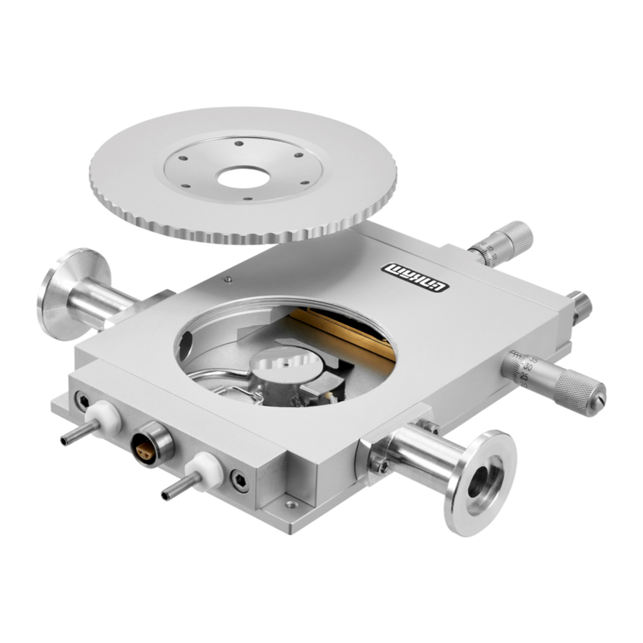
Page 7: Stage Anatomy
Stage Anatomy 1. Lemo connector for Stage Connection Lead 2. Heating element carrier assembly 3. Platinum temperature sensor 4. 22mm Diameter copper heating block (nickel plated) 5. Sample chamber 6. X-Sample manipulator 7. Door locking thumbscrew 8. Liquid nitrogen cooling connector 9. -
Page 8: Stage Assembly
Mounting Stage to Microscope with Dovetail Substage The following description is for mounting the stage on to microscopes which have a circular dovetail substage assembly. Attach the curved stage clamps (part no. 9542) to the base of the stage using the supplied hex screws and the outer most holes in the base plate. -
Page 9: Vacuum Tweezers
Vacuum Tweezers The vacuum tweezers are used to manipulate the glass sample slides onto the silver block to pre- vent fingerprints on the glass and scratching the surface of the silver block when using standard fine tip metal tweezers. The System is supplied with a Vacuum Tweezers Kit which consists of a Vacuum Pump (1) and tweezers (2). -
Page 10: Connecting The Instruments
T95 System Controller manual. T95 back panel Connect the Stage Cable to the Lemo Connector on the FDCS196 stage and connect the other end to the Stage Connection Socket (1). Connect the cable from the Pirani Gauge to the Slot 4;... -
Page 11: Lnp95 Cooling Pump Connection
LNP95 Cooling Pump Connection Remove Transit Screws Before using the LNP95 remove the 4 transit screws, marked by small yellow labels (2), from the base of the LNP95. Transit screws shown by arrows in the adjacent image. These screws hold the pumps in place for shipping. -
Page 12: Connecting The Pirani Gauge
Connecting the Pirani Gauge The surfaces where the O-ring (1) sits should be completely free of dirt. The O-rings should be smeared with a small amount of vacuum grease before loading in between the Pirani Gauge (2) and the Stage Vacuum Connector (3). Ensure that the O-ring is correctly seated in the gauge and vacuum connector before tightening the Clamping Bracket (4) screw (5). -
Page 13: Flexible Stainless Steel Vacuum Tube Connection
Clamping Bracket (4) screw (5). Connect the other end of the Flexible Stainless Steel Vacuum Tube to a Vacuum Pump. Vacuum Pump Note: the FDCS196 is only tested with a vacuum of 10 mBar. Do not use a vacuum lower than this. -
Page 14: Fdcs196 Pro System Setup
Mounting the MV196 The MV196 has an vacuum flange just like the vacuum ports on the sides of the FDCS196 Stage. Use a small amount of vacuum grease to coat a thin layer on the surface where the O-ring will sit. -
Page 15: Sample Preparation And Loading
Sample Preparation and Loading The stage chamber must first be prepared for vacuum. Ensure that the chamber is completely clean and dry inside. Finger grease and dirt must be cleaned off with IPA (isopropanol). Sample Loading Using G16.3 Sample Holder A Freeze Drying Sample is prepared using a G16.3 Sample Holder (1). - Page 16 At standard atmospheric pressure the contact between the sample and the silver block is enough to establish good thermal contact as the air mole- cules in any minute scratches will conduct the heat, but when pulling a vacuum these are drawn out of the stage.
- Page 17 Pipette 2μl of sample on the Quartz Sample Win- dow inside the Shim Spacer. Use the supplied Vacuum Tweezers or a pair of tweezers place a clean W13G, (13 x 0.17mm) Glass Sample Window on top of the sample, ensuring it touches the Shim Spacer. Use the XY manipulators to move the Sample Holder so the edge of the sample sits across the aperture hole of the silver block.
-
Page 18: Sample Loading Using Fdcs196/Cc Crucible Carrier And Quartz Crucible
Sample Loading Using FDCS/CC Crucible Carrier and Quartz Crucible This method is used if you are preparing the sam- ple away from the FDCS196 stage. The crucible carrier has two spring clips to hold the crucible flat against the silver block. This is to ensure good thermal contact. - Page 19 Pipette 2μl of sample inside the Shim Spacer. Use the supplied Vacuum Tweezers or a pair of tweezers to place a clean W13G, (13 x 0.17mm) Glass Sample Window on top of the sample, ensure it touches the Shim Spacer. Before loading the Crucible Carrier the silver block must be prepared with silicon oil to provide a good thermal contact between the crucible and...
- Page 20 Load the Crucible Holder with the prepared sam- ple into the FDCS196 stage. Unscrew the Y manipulator (the one screwed into the stage door) so that when you close the door, the FDCS/CC doesn’t push the crucible right off the edge of the block and the silicon oil with it.
-
Page 21: Cooling Connections
Cooling Connections The Dewar Siphon (1) is the thick white foam tubing and is attached to the liquid nitrogen Dew- ar. The thin black capillary tube inside the white foam tube must be inserted into the liquid nitro- gen cooling connectors on the stage. The white tubing slides on to the outside of the connector. -
Page 22: Using The Fdcs196 System
Note: a graphical indicator of the valve position between the Close and Open position can be seen in Motorised Vacuum Valve Indicator Bar (5). Note: to take the FDCS196 back to atmospheric pressure, turn off the vacuum pump and click on Open Vale icon (6). -
Page 23: Using T95-Linkpad To Control Mv196 Motorised Vacuum Valve
Touch the Confirm icon (4) to go back to the main screen. If you have the FDCS196 Pro System with the MV196 Motorised Valve connected there is an extra column labelled ‘Vac mBar / kPa’ displayed in the main screen (5). -
Page 24: Vacuum Parameters
Vacuum Parameters Touch the active area (1) to change the main screen to the Vacuum menu screen. In the Vacuum main screen there will be 3 options to control the Vacuum value. 1. Auto: in this mode the motorised valve will automatically adjust itself to your programmed vacuum value. -
Page 25: Running A Profile With Vacuum
3. Max: in this mode the motorised valve will close fully to get the maximum vacuum from the vacuum pump. Touch the Max button (1) and make sure the word ‘max’ (2) is displayed under the word ‘Vac’ to set the Ramp to Max mode. -
Page 26: Appendix
“click” when the two parts are connected properly. To remove the Gas Insert, just push back the outer sleeve of the Gas connector toward the base of the FDCS196 Stage and the Gas Insert should drop out. -
Page 27: Fdcs/Cc Crucible Carrier And Quart Crucible
FDCS/CC Crucible Carrier and Quartz Crucible By using the FDCS/CC sample carrier (1), sample can be loaded into the stage without removing the stage lid. The crucible carrier is loaded through the side door. The crucible carrier has two spring clips to hold the crucible flat against the silver block. - Page 28 Open the side door of the stage by unscrewing the thumbscrew and carefully push the FDCS/CC and crucible into the XY slide mechanism. The crucible will be guided to the surface of the silver block by the Sample Holder Ramp. Close the door and tighten the thumbscrew to seal the stage.
-
Page 29: Cooling Connections
Cooling Connections These connections need only be made if the experiments are to be carried out below room temperature. The Dewar siphon (1) is the thick white foam tubing and is attached to the liquid nitrogen Dew- ar. The thin black capillary tube inside the white foam tube must be inserted into the liquid nitro- gen cooling connectors on the stage. -
Page 30: Purging Procedure
Purging Procedure Before starting a cooling experiment, you will need to purge air from the stage chamber with dry nitrogen. This will remove the water in the air which would otherwise condense and freeze on the sample disrupting your image quality. Before you can start purging, the LNP95 must be set to manual mode. - Page 31 Purging the Stage Method 1 There are two methods for purging the stage. Method 1 uses recycled nitrogen gas produced by the LNP95 from the Dewar. Make sure the stage lid is in place and the stage door is closed. Switch on the temperature programmer and set the limit to 40°C.
- Page 32 Purging the Stage Method 2 This method uses an inert gas from a gas cylinder to purge the stage at temperatures above ambient when the LNP95 is not required. 1. Make sure the Stage Lid is in place and the Stage Door is closed.
- Page 33 Window Assembly Lid Window Assembly To replace the windows in the Stage Lid (1) use the Window Tool (2) and align the two wide spacing pins to the Tube Clip Holder holes and unscrew the Lid Insert (3). The Stage Lid and Lid Insert should be turned upside down as shown in the diagram opposite and reassembled in the order indicated.
-
Page 34: Spares And Accessories
The FDCS196 heating element is extremely durable if used carefully. However, it is made from pure silver which is a soft metal. It can be easily scratched, which will compromise the heat flow to the sample and reduce accuracy. - Page 35 Part No. Part Name Part Description FDCS Spare 7504 Spare windows for Lid, Base and samples Windows Kit W16G 16mm diameter Glass Sample Window (0.17mm thick) Box of 100 W22G0.3 22mm diameter Glass Lid/base Window (0.3mm thick) Box of 50 Silicon Rings for Lid and Base (Set of 4) FDCS SP Spacer for sample prep in FDCS (OD: 14mm x ID: 12mm x70 micron x40...
-
Page 36: Troubleshooting
Troubleshooting Cooling fault diagnosis Ensure that all connections to the stage and Dewar are as described in the specific manual and that the stage lid and top windows are properly sealed. 1. The cooling rate is less than programmed. There can be several causes of this problem, the most likely being that one of the connectors has become blocked or damaged. - Page 37 This page is intentionally blank...
- Page 38 This page is intentionally blank...
- Page 39 This page is intentionally blank...
-
Page 40: Contact Details
Linkam Scientific Instruments Ltd Tel: +44(0)1737 363 476 Fax: +44(0)1737 363 480 Email: support@linkam.co.uk Unit 8 Epsom Downs Metro Centre Waterfield, Tadworth, Surrey, KT20 5LR, UK www.linkam.co.uk Version: 1.01.012010...
Need help?
Do you have a question about the FDCS196 and is the answer not in the manual?
Questions and answers