Table of Contents
Advertisement
Quick Links
Advertisement
Table of Contents

Related Manuals for Linkam Scientific Instruments FDCS196


Summary of Contents for Linkam Scientific Instruments FDCS196
- Page 1 Linkam Scientific Instruments FDCS196 / THMS350V Vacuum Stage USER GUIDE...
-
Page 2: Table Of Contents
Mounting the MV196 ....................12 Sample Preparation and Loading ..................13 Sample Loading Using G16.3 Sample Holder ..............13 Sample Loading Using FDCS196/CC Crucible Carrier and Quartz Crucible ....... 16 Cooling Connections ......................19 Filling the Liquid Nitrogen Dewar ................. 19 Appendix .......................... -
Page 3: Stages Covered By This Manual
Stages covered by this manual The following Linkam stages are covered in this manual: FDCS196 Freeze drying cryo stage. THMS350V High temperature vacuum stage THMSEL350V High temperature vacuum stage with ellipsometry Before Setting Up Your Equipment Please register your products by going to the technical support section of our web site www.linkam.co.uk... -
Page 4: Important Notice
Important Notice Please check that your Linkam equipment has not been damaged during transit. If there is any evidence of external damage DO NOT SWITCH ON ANY ELECTRICAL ITEMS. Contact LINKAM SCIENTIFIC or their appointed distributor immediately. Your warranty may be impaired if Linkam is not informed of any transport damage within 7 working days of delivery. -
Page 5: Safety Precautions
Safety Precautions 1) Read this guide before using the equipment. Save these instructions for later use. 2) Follow all warnings and instructions which may be placed on the stage. 3) Never use the equipment if any cables have been damaged. Do not allow any heavy objects to rest on the cables. -
Page 6: Introduction
Aperture hole: 1.3mm Weight: 0.6Kg FDCS196 System The system consists of a FDCS196 stage, a T95- LinkPad System Controller, LNP95 liquid nitro- gen cooling pump system, Pirani vacuum gauge and LINK software. The FDCS196 Pro System has an additional 1.5L Vacuum Pump and MV196 motorised vacuum valve control System. -
Page 7: Stage Anatomy
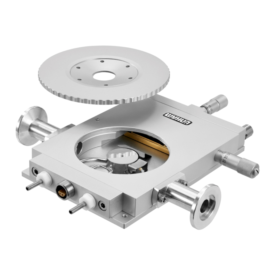
Stage Anatomy 1. Lemo connector for Stage Connection Lead 2. Heating element carrier assembly 3. Platinum temperature sensor 4. 22mm Diameter heating block 5. Sample chamber 6. X-Sample manipulator 7. Door locking thumbscrew 8. Liquid nitrogen cooling connector 9. Heating element wire 10. -
Page 8: Mounting Stage To Microscope With Dovetail Substage
Mounting Stage to Microscope with Dovetail Substage The following description is for mounting the stage on to microscopes which have a circular dovetail substage assembly. Attach the curved stage clamps (part no. 9542) to the base of the stage using the supplied hex screws and the outer most holes in the base plate. -
Page 9: Vacuum Tweezers
Vacuum Tweezers The vacuum tweezers are used to manipulate the glass sample slides onto the silver block to prevent fingerprints on the glass and scratching the surface of the silver block when using standard fine tip metal tweezers. The System is supplied with a Vacuum Tweezers Kit which consists of a Vacuum Pump (1) and tweezers (2). -
Page 10: Connecting The Pirani Gauge
Connecting the Pirani Gauge The surfaces where the O-ring (1) sits should be completely free of dirt. The O-rings should be smeared with a small amount of vacuum grease before loading in between the Pirani Gauge (2) and the Stage Vacuum Connector (3). Ensure that the O-ring is correctly seated in the gauge and vacuum connector before tightening the Clamping Bracket (4) screw (5). -
Page 11: Flexible Stainless Steel Vacuum Tube Connection
Clamping Bracket (4) screw (5). Connect the other end of the Flexible Stainless Steel Vacuum Tube to a Vacuum Pump. Vacuum Pump Note: the FDCS196 is tested with a vacuum of mBar. Do not use a vacuum lower than this. -
Page 12: Fdcs196 Pro System Setup
Mounting the MV196 The MV196 has an vacuum flange just like the vacuum ports on the sides of the FDCS196 Stage. Use a small amount of vacuum grease to coat a thin layer on the surface where the O-ring will sit. -
Page 13: Sample Preparation And Loading
Sample Preparation and Loading The stage chamber must first be prepared for vacuum. Ensure that the chamber is completely clean and dry inside. Finger grease and dirt must be cleaned off with IPA (isopropanol). Sample Loading Using G16.3 Sample Holder A Freeze Drying Sample is prepared using a G16.3 Sample Holder (1). - Page 14 At standard atmospheric pressure the contact between the sample and the silver block is enough to establish good thermal contact as the air molecules in any minute scratches will conduct the heat, but when pulling a vacuum these are drawn out of the stage. Objective immersion oil (supplied) has the same refractive index as quartz and ensures an almost perfect thermal seal between block and crucible.
- Page 15 Pipette 2μl of sample on the Quartz Sample Win- dow inside the Shim Spacer. Use the supplied Vacuum Tweezers or a pair of tweezers place a clean W13G, (13 x 0.17mm) Glass Sample Window on top of the sample, ensuring it touches the Shim Spacer. Use the XY manipulators to move the Sample Holder so the edge of the sample sits across the aperture hole of the silver block.
-
Page 16: Sample Loading Using Fdcs196/Cc Crucible Carrier And Quartz Crucible
Sample Loading Using FDCS/CC Crucible Carrier and Quartz Crucible This method is used if you are preparing the sample away from the FDCS196 stage. The crucible carrier has two spring clips to hold the crucible flat against the silver block. This is to ensure good thermal contact. - Page 17 Pipette 2μl of sample inside the Shim Spacer. Use the supplied Vacuum Tweezers or a pair of tweezers to place a clean W13G, (13 x 0.17mm) Glass Sample Window on top of the sample, ensure it touches the Shim Spacer. Before loading the Crucible Carrier the silver block must be prepared with silicon oil to provide a good thermal contact between the crucible and...
- Page 18 Load the Crucible Holder with the prepared sample into the FDCS196 stage. Unscrew the Y manipulator (the one screwed into the stage door) so that when you close the door, the FDCS/CC doesn’t push the crucible right off the edge of the block and the silicon oil with it.
-
Page 19: Cooling Connections
Cooling Connections These connections need only be made if the experiments are to be carried out below room temperature. The Dewar Siphon (1) is the thick white foam tubing and is attached to the liquid nitrogen Dew- ar. The thin black capillary tube inside the white foam tube must be inserted into the liquid nitro- gen cooling connectors on the stage. -
Page 20: Appendix
“click” when the two parts are connected properly. To remove the Gas Insert, just push back the outer sleeve of the Gas connector toward the base of the FDCS196 Stage and the Gas Insert should drop out. -
Page 21: Window Assembly
Window Assembly Lid Window Assembly To replace the windows in the Stage Lid (1) use the Window Tool (2) and align the two wide spacing pins to the Tube Clip Holder holes and unscrew the Lid Insert (3). The Stage Lid and Lid Insert should be turned upside down as shown in the diagram opposite and reassembled in the order indicated. -
Page 22: Troubleshooting
Troubleshooting Cooling fault diagnosis Ensure that all connections to the stage and Dewar are as described in the specific manual and that the stage lid and top windows are properly sealed. 1. The cooling rate is less than programmed. There can be several causes of this problem, the most likely being that one of the connectors has become blocked or damaged. -
Page 23: Alternative Configuration: Thms350V
Alternative configuration: THMS350V Thank you for purchasing the THMS350V tem- perature controlled vacuum system. Please take the time to read through the manual as it will help you to make the most out of the equipment. THMS350V Stage Specifications Objective Lens WD: 4.6mm Condenser lens WD: 12.5mm... -
Page 24: Thms350V Stage Anatomy
THMS350V Stage Anatomy Stage Assembly 1. Lemo connector for Stage Connection Lead 2. Heating element carrier assembly 3. Platinum temperature sensor 4. 22mm Diameter copper heating block (nickel plated) 5. Sample chamber 6. X-Sample manipulator 7. Door locking thumbscrew 8. Liquid nitrogen cooling connector 9. -
Page 25: Alternative Configuration: Thmsel350V
Alternative configuration: THMSEL350V Thank you for purchasing the THMSEL350V Stage. Please take the time to read through the manual as it will help you to get the most out of the equipment. For work below ambient temperature vacuum must be used to reduce condensation inside the stage and on sample. -
Page 26: Thmsel350V Stage Anatomy
THMSEL350V Stage Anatomy Stage Assembly 1. Lemo connector for Stage Connection Lead 2. Heating element carrier assembly 3. Platinum temperature sensor 4. 22mm copper nickel plated block 5. Sample chamber 6. X-Sample manipulator 7. Door locking thumbscrew 8. Liquid nitrogen cooling connector 9. -
Page 27: Using The Ellipsometer Stage With Vacuum Port
Using The Ellipsometer Stage With Vacuum Port For ease of transportation the stage is supplied with the Gas Port (1) attached. When using the Stage at temperatures below ambient to –196ºC, YOU MUST USE the vacuum ports so that all moisture is removed by connect- ing to a vacuum pump. -
Page 28: Ellipsometer Windows Assembly
Ellipsometer Windows Assembly If the windows need to be replaced they should be reassembled as shown in the diagram. Top Window Assembly Use the Window Tool (1) to remove the 22mm Locking Ring (2) and reassembled the Top Win- dow as shown in the diagram. 1. - Page 29 This page is intentionally blank...
- Page 30 This page is intentionally blank...
- Page 31 This page is intentionally blank...
-
Page 32: Contact Details
Linkam Scientific Instruments Ltd Tel: +44(0)1737 363 476 Fax: +44(0)1737 363 480 Email: support@linkam.co.uk Unit 8 Epsom Downs Metro Centre Waterfield, Tadworth, Surrey, KT20 5LR, UK www.linkam.co.uk Version: 1.01.012010...
Need help?
Do you have a question about the FDCS196 and is the answer not in the manual?
Questions and answers