
Related Manuals for TANACOM BULL 750

Summary of Contents for TANACOM BULL 750
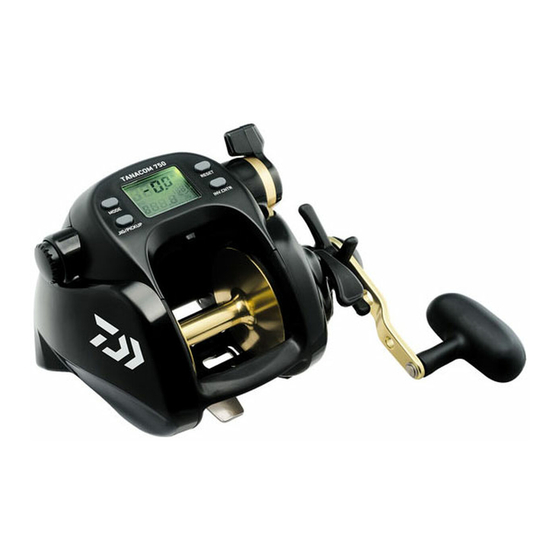
- Page 1 OPERATING MANUAL Thank you for purchasing a TANACOM BULL 750. To take full advantage of the reels many useful functions, please read this manual carefully before using. Retain this manual for future reference. Reference Reference...
-
Page 2: Table Of Contents
Index Caution 11. Display recalibration Precautions Display revision 12. How to fix the Rod Clamp Power source How to connect the reel to the power source Useful functions About the power source Various alarms Battery checking displays Display light Breaker display Using the Reel About the counter display... -
Page 3: Caution
Caution Precautions 1. When electricity is applied, a weak radio wave is generated and may effect hearing aids, cardiac pacemakers, and other medical devices causing malfunctions. Especially for those who use a cardiac pacemaker, the electric reel may cause palpitations and dizziness, so you should consult the manufacturer of your electrical medical device or the distributor for the effect of radio waves. -
Page 4: Power Source
Power source How to connect the reel to the power source Attach the cord clips to the battery. Red covered clip is the plus (+), and the black covered clip is the minus (-). Main bodyʼs power supplier Insert the connector into the reel. After this, the display appears as below. -
Page 5: Using The Reel
Using the Reel Do not jerk your rod to free a lure or sinker stuck on the bottom. Pull the line taught with a gloved hand and cut it. After maintenance, be sure to loosen the drag and store the reel in a dry place. -
Page 6: Maintenance
Maintenance About maintenance This is a washable reel. Wash away salt residue and grit after fishing Maintenance procedure Wash the reel with a dish washing detergent and a soft sponge. Do not use solvents. Do not use soap or other detergents. Other soaps or solutions may damage the reel both externally and internally. -
Page 7: Maintenance
Maintenance Handling and maintenance of the power cord Follow the restrictions below to avoid cord problems. Do not cut or connect your cord by yourself as it can cause unintended problems. Do not hang the reel Do not wind the power by the power cord. -
Page 8: Names Of The Buttons And The Display
Names of the buttons and the display MODE BUTTON RESET BUTTON INVERSE COUNTER BUTTON JIG/PICKUP BUTTON Mode display Depth counter Chumming timer (Power indicator, time to wind up, timer display) Jigging display Inverse counter (winding speed display) -
Page 9: Names Of The Buttons And The Display
Names of the buttons and the display MODE BUTTON Press the MODE BUTTON to scroll through the adjustment displays for each reel function. - Use the Power Lever to adjust numeric values. - Pressing the MODE BUTTON sets the numeric values you have adjusted. - Depress and hold the MODE BUTTON to return to the depth display. -
Page 10: Names And Functions Of Each Part
Names and functions of each part Free spool adjustment strong weak Power lever tighten loosen Waterproof drag Clutch Levelwind Input Roller Enclosed items Levelwind threader Storage bag Manual CD-R Power cord Rod Clamp Input Roller... -
Page 11: Names And Functions Of Each Part
Names and functions of each part Free spool adjustment - It adjusts brake tension on the spool to prevent backlash or line slack caused by dropping the line with hook and sinker. Power lever - You can freely adjust winding power, or winding speed, from zero(ON/OFF) to maximum, by 32 steps, by using the lever. -
Page 12: Line Data Input
Line data input (with Input Roller) You can also set the main line utilizing the Input Roller. Line data input See animation With lnput Roller Run the line through the Level Wind Guide and tie it onto the Levelwind Guide Main line spool. - Page 13 Line data input (with Input Roller) Take off the Input Roller. Pull the Power Lever to the OFF position once again. (The beep will then be heard.) Push again the Power Lever forward to maximum and wind the Do not reel in the end of the line Line’s end remaining line to fill the spool.
- Page 14 Line data input (When line length is known---P1) This method is used when the line length is known before winding. In the example below, PE 6 – 700m is wound. Run line through the levelwind guide and tie it onto the spool. Levelwind Guide Main line The levelwind threader makes this process easier.
- Page 15 Line data input (When line length is known---P1) Pull the power lever back to the OFF position when only about 10 m of the line to be wound remains. (This will stop electric winding.) (Alarm sound) Do not wind up the end of the line. Turn the power lever at OFF position before the end (stop electric winding), and wind up the remaining line manually.
- Page 16 Line data input (With backing line---P2) This method requires use of Daiwa braided line that is color coded to show length and has a total length greater than 100 m. Pass the backing line through the hole of the Levelwind to be Levelwind Guide Main line tied onto the pin found on the spool, and then turn the power...
- Page 17 Line data input (With backing line---P2) As indicated by the lineʼs color coding, wind the line up until the remaining line is 100m. With the power lever moved forward, changes into a tension indicator. Adjust the tension to between 5 and 7 on the right side of the panel.
- Page 18 Line data input (Backing line 2---P3) This procedure is to enter the line length after it has been wound onto the reel. It is necessary that you know the line length and that it is greater than 100m. Turn the power on while the main line is wound up. Press the MODE BUTTON for more than 5 seconds while it is...
-
Page 19: Line Data Input
Line data input (Backing line 2---P3) Pull an additional 50m of line from the spool. Pull out additional 50 m of line and then press the RESET BUTTON for more than 2 seconds. (The line is pulled out for 100 m in total.) It displays 100.0 and this is the completion of the input procedure. - Page 20 Functional setting operation (1. Mode setting display) How to set the many functions available 1.There are many useful functions in the mode 2.While the mode setting display is on, operate the power lever to change it to a desired value, and then press the MODE BUTTON to complete the procedure.
- Page 21 Functional setting operation (1. Mode setting display) Set a desired value with the power lever. Power lever At its MAX position, numbers count upward rapidly. At the OFF position, numbers count downward rapidly. Around mid position, numbers change at a slower pace. Press the MODE BUTTON when your desired value is shown.
-
Page 22: Surface Depth Setting
Functional setting operation (2. Before you begin fishing.) Surface depth setting Before you begin fishing, make sure the counter is set to zero at the waterʼs surface. This is extremely important to ensure accurate fishing depth readings. After installing the reel on your rod, pass the main line through the guide (from bottom to tip of the rod) and set a rig. -
Page 23: Auto Stop Setting
Functional setting operation (3. Auto stop function) Auto stop setting The Auto stop depth may be set to meet your own specific needs. - Auto stop adjusts to operate at depths from 1 m to 5 m (in 10 cm increments). - It prevents accidentally winding swivels, terminal rigs etc. -
Page 24: Line Sending Function
Functional setting operation (4. Line sending function) Line sending function The spoolʼs motor assists in winding out the line. - The line sending mechanism begins to work at a depth of 2.5 m below the pre-set auto stop depth. - When the clutch is on during line feeding, the motor runs, so be careful that the spool is rotating to the winding direction. - Page 25 Functional setting operation (5. Pickup speed setting) Pickup speed preference Press MODE BUTTON. If the display is at display, then move the power lever or press RESET BUTTON to show the display shown on the right. Press MODE BUTTON again. This display is the pickup setting display.
-
Page 26: Inverse Counter
Functional setting operation (6. Inverse counter) Inverse counter Two counters are better than one. This reel has counters from both the surface and from the bottom. -As the default setting of the inverse counter, it displays the measured winding speed during electrical winding. If you want to use it as the inverse counter as in the previous model, turn on the inverse counter (See page 28). -
Page 27: Jigging
Functional setting operation (7. Jigging) Jigging Jigging is an extremely valuable function. After setting your preferences, pressing the JIG/PICKUP BUTTON starts the function. Speed of the jigging can be adjusted with the power lever. Press the MODE BUTTON to show Jig/pickup display. (The figure at right shows the default pickup display. - Page 28 Functional setting operation (7. Jigging) Jigging master You can choose the jigging pattern, range, waiting time and length you require. - Pressing the JIG/PICKUP BUTTON, starts jigging, with the display showing the indicator. (Pressing the button once more cease jigging.) The power lever controls jigging speed. - Shifting of jigging speed is done easily with the lever control.
-
Page 29: Jigging
Functional setting operation (7. Jigging) 3. Waiting time You can choose the waiting time between jigs. The interval time is set in seconds. Example) Three-step jigging Three-step jigging (Preference setting) 5 seconds interval time Interval time (5sec) Three-step jigging Interval time (5sec) (Shown is the interval time set to 5 sec) -
Page 30: Winding Speed Indicator
Functional setting operation (8. Winding speed indicator) Winding speed display In the default setting, the lower area counter displays the winding speed. The chumming timer display area shows the remaining time until the auto stop is reached. (p. 29) The inverse counter numbers can be changed to indicate winding speed. -
Page 31: Displaying Of The Remaining Time To Auto Stop
Functional setting operation (9. Remaining time to auto stop) Displaying of the remaining time to auto stop Two counters are better than one. This reel has counters from both the surface and from the bottom. When the display is set to indicate the actual speed, the chumming timer display portion indicates the remaining time before it reaches the auto stop position. -
Page 32: Chumming Timer Winding
Functional setting operation (10. Chumming timer winding) Chumming timer winding The right timing for the best results. After a pre-determined amount of time (in minutes) has passed, the reel starts winding automatically. - After pre-set 5 minutes have passed, the reel automatically winds up. -
Page 33: Chumming Timer Winding
Functional setting operation (10. Chumming timer winding) Press MODE BUTTON twice. - When the display goes back to depth counter, then the procedure is completed. - The indicator is seen on the display. - The time set can be checked by pressing the INVERSE COUNTER BUTTON. -
Page 34: Display Recalibration
Functional setting operation (11. Display recalibration) Display revision You can recalibrate the counter should it not indicate an accurate depth compared to depth markings on your line. Example below is the case in which, though the counter shows 103 m, color markings on the line indicate 100 m. Press the MODE BUTTON to display real fishing time and total... -
Page 35: How To Fix The Rod Clamp
Functional setting operation (12. How to fix the Rod Clamp) When you use a metallic bat or for your fishing of a big charge, you should always utilize the Rod Clamp. (sing the Rod Clamp, it is possible to cramp rods with diameter up to 25-34mm) Insert the Bolt in the clamp setting hole, and fix it by tightening the Nut and the Washer. -
Page 36: Useful Functions
Useful functions Various alarms Many kinds of information are indicated by audible alarms. Power lever alarm - Placing the Power lever at MAX or OFF positions evokes an alarm. Auto stop alarm - While winding up, starting 6 m below the auto stop depth, an alarm beeps at two meter intervals. Upon reaching the auto stop depth, a long alarm sounds. -
Page 37: Reel Specifications
Reel Specifications Reel Specification list Product name TANACOM BULL 750 Product code 40801005 Gear ratio(manual winding) 2.3 : 1 Weight (g/oz) 1260 g / 44.4 oz Max Drag power (kg/lb) 22kg/48lb Line Capacity (m) DAIWA BRAIDED MONO BRAIDED PE6(80lb)-700m(770yds) 30lb-700m(770yds) -
Page 38: Parts List
Parts List TANACOM BULL750 TANACOM BULL750 Parts No, Parts Name Parts No, Parts Name Parts No, Parts Name 6H377601 IC MODULE L/S PLATE SET 6F594101 SPOOL PLATE 63538705 R/S PLATE SCREW(A) 6E033201 BRAKE CLICK SPRING 6F206901 SPOOL PLATE SCREW 6F598301... -
Page 39: Trouble Shooting
Trouble shooting Ref. Symptom Possible causes To do page It is a normal function to avoid over The counter displays winding. Press RESET BUTTON 21,22 continue winding. Motor does not Pull the lever to OFF and then move Did not pull the lever to OFF respond to the forward again to start winding. - Page 40 Reference/Référence/Hinweis Instrucciones/Riferimenti COMPANY DAIWA FRANCE S.A.S COMPANY DAIWA SPORTS LIMITED NAME NAME 25 BOULEVARD INDUSTRIEL Netherton Industrial Estate, BP 30208 Wishaw ML2 0EY, ADDRESS ADDRESS 76304 SOTTEVILLE LES Lanarkshire,Scotland, U.K. ROUEN CEDEX. FRANCE 02-32-91-96-50 01698-355-723 TEL NO. TEL NO. http://www.daiwa-france.fr/ http://www.daiwasports.co.uk/ Web Address Web Address...
Need help?
Do you have a question about the BULL 750 and is the answer not in the manual?
Questions and answers