Table of Contents
Advertisement
Quick Links
Download this manual
See also:
Owner's Manual
QQ
3 7 63 1515 0
DVD-S2300MK2
TE
L 13942296513
I CONTENTS
TO SERVICE PERSONNEL .......................................... 2
LOCALE MANAGEMENT INFORMATION ................... 4
FRONT PANEL .............................................................. 5
REMOTE CONTROL PANEL ........................................ 5
REAR PANEL ................................................................ 6
SPECIFICATIONS .......................................................... 6
INTERNAL VIEW ........................................................... 7
DISASSEMBLY PROCEDURES ............................. 8~12
REPLACEMENT PROCEDURE .................................. 13
SERVICE MODE AND SELF-DIAGNOSIS FUNCTION ... 14~18
www
.
1 0 0 8 6 6
http://www.xiaoyu163.com
DVD AUDIO/VIDEO SACD PLAYER
This manual has been provided for the use of authorized YAMAHA Retailers and their service personnel.
It has been assumed that basic service procedures inherent to the industry, and more specifically YAMAHA Products, are already
known and understood by the users, and have therefore not been restated.
WARNING:
Failure to follow appropriate service and safety procedures when servicing this product may result in personal
injury, destruction of expensive components, and failure of the product to perform as specified. For these reasons,
we advise all YAMAHA product owners that any service required should be performed by an authorized
YAMAHA Retailer or the appointed service representative.
IMPORTANT:
The presentation or sale of this manual to any individual or firm does not constitute authorization, certification or
recognition of any applicable technical capabilities, or establish a principle-agent relationship of any form.
The data provided is believed to be accurate and applicable to the unit(s) indicated on the cover. The research, engineering, and
service departments of YAMAHA are continually striving to improve YAMAHA products. Modifications are, therefore, inevitable
and specifications are subject to change without notice or obligation to retrofit. Should any discrepancy appear to exist, please
contact the distributor's Service Division.
WARNING:
Static discharges can destroy expensive components. Discharge any static electricity your body may have
accumulated by grounding yourself to the ground buss in the unit (heavy gauge black wires connect to this buss).
IMPORTANT:
Turn the unit OFF during disassembly and part replacement. Recheck all work before you apply power to the unit.
x
ao
y
i
http://www.xiaoyu163.com
8
SERVICE MANUAL
IMPORTANT NOTICE
Q Q
3
6 7
1 3
MECHANISM UNIT ................................................ 19~28
OPTICAL PICKUP TILT ADJUSTMENT ............... 29~30
ELECTRICAL CONFIRMATION ............................ 30~31
DISPLAY DATA ..................................................... 32~33
IC DATA ................................................................. 34~37
PIN CONNECTION DIAGRAM .................................... 37
PRINTED CIRCUIT BOARD .................................. 38~46
BLOCK DIAGRAM ................................................. 46~47
SCHEMATIC DIAGRAM ........................................ 48~63
PARTS LIST ........................................................... 64~74
REMOTE CONTROL .................................................... 75
u163
.
2 9
9 4
2 8
1 5
0 5
8
2 9
9 4
m
co
P.O.Box 1, Hamamatsu, Japan
9 9
2 8
9 9
Advertisement
Table of Contents

Related Manuals for Yamaha DVD-S2300MK2


Summary of Contents for Yamaha DVD-S2300MK2
-
Page 1: Table Of Contents
This manual has been provided for the use of authorized YAMAHA Retailers and their service personnel. It has been assumed that basic service procedures inherent to the industry, and more specifically YAMAHA Products, are already known and understood by the users, and have therefore not been restated. -
Page 2: To Service Personnel
DVD-S2300MK2 3 7 63 1515 0 I TO SERVICE PERSONNEL 1. Critical Components Information AC LEAKAGE Components having special characteristics are marked s WALL EQUIPMENT TESTER OR and must be replaced with parts having specifications equal OUTLET UNDER TEST EQUIVALENT to those originally installed. - Page 3 DVD-S2300MK2 3 7 63 1515 0 Laser Diode Properties Type: Semiconductor laser GaAlAs Wave length: 658 nm (DVD) 790 nm (VCD/CD) Output Power: CLASS IIa 1mW (DVD) CLASS I 1mW (VCD/CD) VARO! : AVATTAESSA JA SUOJALUKITUS OHITETTAESSA OLET ALTTIINA NÄKYMÄTTÖMÄLLE LASER- SÄTEILYLLE.
-
Page 4: Prevention Of Electro Static Discharge
DVD-S2300MK2 3 7 63 1515 0 I PREVENTION OF ELECTRO STATIC DISCHARGE The laser diode in the traverse unit (optical pickup) may be damaged due to static electricity from clothes or the human body. Use caution to prevent electrostatic damage when servicing or handling the laser diode. -
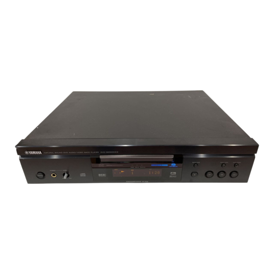
Page 5: Front Panel
DVD-S2300MK2 3 7 63 1515 0 I FRONT PANEL U model I REMOTE CONTROL PANEL U model L 13942296513 u163 http://www.xiaoyu163.com... -
Page 6: Rear Panel
DVD-S2300MK2 3 7 63 1515 0 I REAR PANEL U model I SPECIFICATIONS Output Level * Specifications are subject to change without notice due to product SACD/DVD/VIDEO CD/CD-DA (1kHz 0dB) ....2 V ± 0.3 V improvements. Signal to Noise Ratio SACD/DVD/VIDEO CD/CD-DA ......... -
Page 7: Internal View
DVD-S2300MK2 3 7 63 1515 0 DIMENSIONS 435 (17-1/8") Unit : mm (inch) L 13942296513 I INTERNAL VIEW 1 MAIN (4) P.C.B. 2 RS-232C P.C.B. 3 AUDIO (2) P.C.B. 4 MAIN (1) P.C.B. 5 AUDIO (1) P.C.B. 6 MAIN (5) P.C.B. -
Page 8: Disassembly Procedures
DVD-S2300MK2 3 7 63 1515 0 I DISASSEMBLY PROCEDURES (Remove parts in the order as numbered.) Disconnect the power cable from the AC outlet. 1. Removal of Top Cover a. Remove 4 screws (1) and 3 screws (2). (Fig. 1) b. - Page 9 DVD-S2300MK2 3 7 63 1515 0 Tray Lid 3 x 10 -8 3 x 10 -8 DVD-Mechanism Fig. 4 4. Removal of DVD-mechanism CAUTION • When removing the DVD-Mechanism, make sure to follow steps a. to e. below in that order to prevent the laser diode from being damaged.
- Page 10 DVD-S2300MK2 3 7 63 1515 0 6. Removal of AUDIO P.C.B. a. Remove 4 screws (9). (Fig. 8) b. Disconnect the connectors CB301 ~ CB304 and CB650. (Fig. 9) c. Remove 2 screws (0) and then remove the AUDIO (1) P.C.B. (Fig. 9) 7.
- Page 11 DVD-S2300MK2 3 7 63 1515 0 9. Removal of DVD Module P.C.B. Remove the DVD module P.C.B. with the tip of the 4 Support pinched with pliers or the like. (Fig. 11) 10.Removal of MAIN P.C.B. a. Disconnect the connectors CB606, CB608, CB609 and CB823. (Fig. 12) b.
- Page 12 DVD-S2300MK2 3 7 63 1515 0 Checking the AUDIO P.C.B. • After removing the top cover and inner cover, remove the AUDIO P.C.B. Set the AUDIO P.C.B. upright with its rear panel side upward. (Fig. 14) • Disconnect the cable connected to the AUDIO P.C.B. and then reconnect it via the following extension cable for servicing.
-
Page 13: Optical Pickup Self-Diagnosis And Replacement Procedure
DVD-S2300MK2 3 7 63 1515 0 I OPTICAL PICKUP SELF-DIAGNOSIS AND REPLACEMENT PROCEDURE An optical pickup self-diagnosis function and tilt adjustment check function have been included in this unit. When repairing, use the following procedure for effective Self-diagnosis and tilt adjustment. Be sure to use the self-diagnosis function before replacing the optical pickup when "NO DISC"... -
Page 14: Service Mode And Self-Diagnosis Function
DVD-S2300MK2 3 7 63 1515 0 I SERVICE MODE AND SELF-DIAGNOSIS FUNCTION 1. Service Mode a. Turn on the POWER switch. b. Press the SACD/DVD button to set to the DVD mode, and the DVD mode indicator lights up. - Page 15 DVD-S2300MK2 3 7 63 1515 0 Player mode and Cancellation Item Function Display button combination method CD laser In STOP mode, press CD laser drive current is LDC_028_026 Cancelled ↑ ↑ ↑ drive current " " and " " measured and the result is...
-
Page 16: Test Mode
DVD-S2300MK2 3 7 63 1515 0 3. Test Mode • Starting Test Mode a. Turn on the POWER switch. b. Press the SACD/DVD button to set to the SACD mode, and the SACD mode indicator lights up. c. Press the "... -
Page 17: Service Precautions
DVD-S2300MK2 3 7 63 1515 0 4. Sub-CPU RS-232C check mode 5. Service Precautions • Starting Sub-CPU RS-232C check mode 5.1. Recovery After the DVD Player is Repaired a. With the power turned off, short between pins No.2 When the DVD module P.C.B., or a FROM or an EEPROM (RXD) and No.3 (TXD), and between pins No.7 (RTS) -
Page 18: Error Code
DVD-S2300MK2 3 7 63 1515 0 7. Error Code Description of error Supplementary explanation Faulty point 1 Faulty point 2 Faulty point 3 Faulty point 4 L. H error U11 Focus error H01 Tray loading error ( Spindle servo, DSC SP motor, CLV servo error) -
Page 19: Assembling And Disassembling The Mechanism Unit
DVD-S2300MK2 3 7 63 1515 0 I ASSEMBLING AND DISASSEMBLING THE MECHANISM UNIT 1. Disassembly Procedure 2. Terminal P.C.B. 1. Remove the screws. 2. Remove the solder from the motor connections. 3. Remove the connectors. Solder Connector Screw Screw Connector Terminal P.C.B. - Page 20 DVD-S2300MK2 3 7 63 1515 0 3. Clamp Plate Unit Spread the Stopper with hand to slide the tabs and remove the Clamp Plate Unit. Clamp Plate Unit Clamp Plate Unit Stopper Stopper Stopper 4. Tray Lift the Tray.
- Page 21 DVD-S2300MK2 3 7 63 1515 0 <Precautions in Reassembling the Tray> • Reassemble the Tray so that it is in the backmost position. 1. Turn Traverse Gear until Cam Gear lever comes to the Lever adjusting position at the end of the Mechanical chassis unit.
- Page 22 DVD-S2300MK2 3 7 63 1515 0 b. Inch the Tray frontward until convex phase and concave phase mate. Caution: Make sure to mate convex phase and concave phase properly, so that the gap between Turntable and Tray becomes 5mm or less.
- Page 23 DVD-S2300MK2 3 7 63 1515 0 < P r e c a u t i o n s i n R e a s s e m b l i n g t h e Traverse Block> • T a k e t h e f o l l o w i n g p r e c a u t i o n s w h e n reassembling the Traverse Block.
- Page 24 DVD-S2300MK2 3 7 63 1515 0 7. Optical Pickup Unit 1. Remove the Screws. 2. Remove the Spring Holders and the springs. 3. Pull out the Drive Shaft and Guide Shaft. Pickup Unit Guide Shaft Screw Spring Holder Screw...
- Page 25 DVD-S2300MK2 3 7 63 1515 0 7.2 Disassembling the Optical Pickup Unit 1. Remove 2 screws (A) and remove the TRV feed rack. 2. Remove the screw (B) and remove the Terminal FPC. 3. Remove the Optical Pickup. Screw A...
- Page 26 DVD-S2300MK2 3 7 63 1515 0 3. Install the Optical Pickup Unit, Spring Drive Shaft, Guide Shaft, Rubber Cushion, and Spring Holder on the Traverse Block. At this time, make sure that the Optical Pickup Unit is installed at the rear end of the Guide Shaft.
- Page 27 DVD-S2300MK2 3 7 63 1515 0 4. Cut the Antistatic Flexible Sheet for the Optical Pickup Unit. Cutting Line Antistatic FPC L 13942296513 u163 http://www.xiaoyu163.com...
- Page 28 DVD-S2300MK2 3 7 63 1515 0 8. Disassembling the Middle Chassis 1. Remove the Holder Pins. 2. Remove the Tab. 3. Lift it while pulling it in the direction of the arrow. Holder Pin Middle Chassis 9. Disassembling the Traverse Gear A / FG Unit 1.
-
Page 29: Optical Pickup Tilt Adjustment
DVD-S2300MK2 3 7 63 1515 0 I OPTICAL PICKUP TILT ADJUSTMENT 9. Adjust tilt adjustment screw 2 so that the jitter value is Adjustment point Tangential adjustment screw, minimized. Tilt adjustment screw 10. Repeat adjusting tilt adjustment screws 1 and 2... -
Page 30: Electrical Confirmation
DVD-S2300MK2 3 7 63 1515 0 5. Procedure for Screw Lock 1. After adjustment, remove the top cover, tray, clamper base and traverse unit in this sequence. 2. Lay the traverse unit upside down and lock the adjustment screw with screw lock. - Page 31 DVD-S2300MK2 3 7 63 1515 0 2. Video Output (Chrominance Signal) Confirmation Measurement point Mode Disc S-Video output terminal (C OUT) PLAY DVDT-S15 (Title 10), DVDT-S01 (Title 48) Color bar 100% Measuring equipment, tools Adjustment value Screwdriver, Oscilloscope 779 mVp-p ± 40mV 200mV/div 10µsec/div...
-
Page 32: Display Data
DVD-S2300MK2 3 7 63 1515 0 I DISPLAY DATA V701: 14-BT-77GN (V9910400) G LEAD DETAILS ™ G PIN CONNECTION Pin No. Connection Pin No. Connection Note : 1) F1, F2 ..Filament 5) DL ..Datum Line 2) NP .. - Page 33 DVD-S2300MK2 3 7 63 1515 0 G ANODE CONNECTION SACD PROG RNDM AUDIO VIDEO TEXT ARTIST MPEG MULTI GROUP TITLE TRACK L 13942296513 CHAP – PAGE – ANGLE – D. MIX – – – – – – – –...
-
Page 34: Ic Data
DVD-S2300MK2 3 7 63 1515 0 I IC DATA IC40: MN102HF60KYD (SACD P.C.B.) MAIN CPU Pin No. u-com port Definition Direction Note WAIT WAIT_SODC Input Bus cycle wait input terminal (SACD) Output Read enable output terminal NWEL/P62 NWEL Output... - Page 35 DVD-S2300MK2 3 7 63 1515 0 IC40: MN102HF60KYD (SACD P.C.B.) MAIN CPU Pin No. u-com port Definition Direction Note P85/SBT3 SCK2 Output Clock output to SUBCPU, E2PROM, FL Driver, IC45, IC46 VREF+ VREF+ Power supply for A/D converter : +3.3V...
- Page 36 DVD-S2300MK2 3 7 63 1515 0 IC823: M30626FHPFP (RS-232C P.C.B.) 16bit µ-COM (SUB CPU) Pin No. u-com port Definition Direction Note ANEX1/SOUT4 ANEX1/SOUT4 Output N.C. ANEX0/CLK4 ANEX0/CLK4 Output N.C. DA1/TB4IN DA1/TB4IN Output N.C. DA0/TB3IN DA0/TB3IN Output N.C. TB2IN/SOUT3 TB2IN/SOUT3 Output N.C.
-
Page 37: Pin Connection Diagram
DVD-S2300MK2 3 7 6 3 1 5 1 5 0 IC823: M30626FHPFP (RS-232C P.C.B.) I PIN CONNECTION DIAGRAM 16bit µ-COM (SUB CPU) • ICs Pin No. u-com port Definition Direction Note Output N.C. Output N.C. NJM7909FA M51951BHP M62723ML PQ05RD21... - Page 38 DVD-S2300MK2 3 7 6 3 1 5 1 5 0 I PRINTED CIRCUIT BOARD • Semiconductor Location I BLOCK DIAGRAM Ref. No. Location D811 RS-232C P. C. B. (Component side) D812 D821 IC821 RS-232C REMOTE CONTROL IC822 IC823 IC825...
- Page 39 DVD-S2300MK2 BLOCK DIAGRAM MAIN P.C.B. AUDIO P.C.B. SACD P.C.B. See page 52 See page 48 See page 49 RS-232C P.C.B. See page 53 IC827 SW810 IC828 IC826 IC829 IC823 IC830 Q822 See page 55 - 62 w w w MAIN P.C.B.
- Page 40 DVD-S2300MK2 3 7 6 3 1 5 1 5 0 I PRINTED CIRCUIT BOARD AUDIO P. C. B. (1) (Component side) MAIN (1) SACD DGND M_MUTE DAC_CLK ADACGND DGND DVD_DMR PHREF0 ADACGND BCKAD DVD_DML DSADML ADACGND DSADMR DVD_FR ZDF_DM...
- Page 41 DVD-S2300MK2 3 7 6 3 1 5 1 5 0 I PRINTED CIRCUIT BOARD • Semiconductor Location Ref. No. Location D301 D302 D303 AUDIO P. C. B. (1) (Foil side) D314 D315 D651 D652 IC320 IC321 IC322 IC323 IC326...
- Page 42 DVD-S2300MK2 3 7 6 3 1 5 1 5 0 I PRINTED CIRCUIT BOARD • Semiconductor Location Ref. No. Location D606 AOUT_L AUDIO (1) Power Transformer Power Transformer MAIN P. C. B. (1) D607 AOUT_R D609 (Component side) D610...
- Page 43 DVD-S2300MK2 3 7 6 3 1 5 1 5 0 I PRINTED CIRCUIT BOARD • Semiconductor Location Ref. No. Location D601 D602 D603 MAIN P. C. B. (1) (Foil side) D604 D605 D608 IC502 IC504 IC505 IC601 IC603 IC607...
- Page 44 DVD-S2300MK2 3 7 6 3 1 5 1 5 0 I PRINTED CIRCUIT BOARD • Semiconductor Location Ref. No. Location D701 D702 MAIN P. C. B. (4) (Component side) MAIN P. C. B. (3) (Component side) D703 AC IN...
-
Page 45: Printed Circuit Board
DVD-S2300MK2 3 7 6 3 1 5 1 5 0 I PRINTED CIRCUIT BOARD • Semiconductor Location Ref. No. Location IC701 Q701 Q702 Q703 MAIN P. C. B. (3) (Foil side) Q704 Q705 1 3 9 4 2 2 9 6 5 1 3 MAIN P. -
Page 46: Block Diagram
DVD-S2300MK2 3 7 6 3 1 5 1 5 0 I PRINTED CIRCUIT BOARD • Semiconductor Location I BLOCK DIAGRAM Ref. No. Location D811 RS-232C P. C. B. (Component side) D812 D821 IC821 RS-232C REMOTE CONTROL IC822 IC823 IC825... - Page 47 DVD-S2300MK2 3 7 6 3 1 5 1 5 0 I PRINTED CIRCUIT BOARD DVD MODULE P. C. B. (Component side) DVD MODULE P. C. B. (Foil side) 1 3 9 4 2 2 9 6 5 1 3...
- Page 48 DVD-S2300MK2 3 7 6 3 1 5 1 5 0 I PRINTED CIRCUIT BOARD SACD P. C. B. (Component side) Mechanism MODULE TERMINAL SACD P. C. B. (Foil side) MAIN (1) AGND D+5S MAIN (2) DGND +2.5S DGND SGND...
- Page 49 DVD-S2300MK2 SCHEMATIC DIAGRAM (MAIN 1/3) Page 49 Page 48 to AUDIO (1) to SACD IC502: BH7862FS 6 ch Video Driver CTRAP 75ohm COUT TTL AND MUTE1 MUTE1 TEST TEST 1.5-6M 75ohm MIXOUT MIXFB YTRAP CLAMP CLAMP PYIN 75ohm YOUT...
- Page 50 DVD-S2300MK2 SCHEMATIC DIAGRAM (MAIN 2/3) IC601 : S-808XXANNP IC603 : M51951BHP IC605, 606: PQ05RD21 Reset Signal Generator System Reset IC608: PQ09RD11 Regulator OUTPUT – – VREF 1.25V IC607: MD1422N IC611: NJM79L05UA Voltage Regulator Voltage Regulator COMMON Page 49 to AUDIO (2)
- Page 51 DVD-S2300MK2 SCHEMATIC DIAGRAM (MAIN 3/3) Page 51 to MAIN (1) IR REMOTE -22.3 Page 48 -18.7 -18.7 FL DRIVER -18.7 -18.7 to SACD -22.3 -24.3 -24.3 -24.3 -24.3 -24.3 -24.3 STANDBY LED DRIVER PRGR LED DRIVER VOFF LED DRIVER...
- Page 52 DVD-S2300MK2 3 7 6 3 1 5 1 5 0 I SCHEMATIC DIAGRAM (DVD MODULE (1/8): FEP SECTION) Page 48 to SACD 1 3 9 4 2 2 9 6 5 1 3 w w w u 1 6 3...
- Page 53 DVD-S2300MK2 3 7 6 3 1 5 1 5 0 I SCHEMATIC DIAGRAM (DVD MODULE (2/8): SODC + DRV SECTION) 1 3 9 4 2 2 9 6 5 1 3 w w w u 1 6 3 http://www.xiaoyu163.com...
- Page 54 DVD-S2300MK2 3 7 6 3 1 5 1 5 0 I SCHEMATIC DIAGRAM (DVD MODULE (3/8): AVDEC SECTION) 1 3 9 4 2 2 9 6 5 1 3 w w w u 1 6 3 http://www.xiaoyu163.com...
- Page 55 DVD-S2300MK2 3 7 6 3 1 5 1 5 0 I SCHEMATIC DIAGRAM (DVD MODULE (4/8): PROGRESSIVE SECTION) 1 3 9 4 2 2 9 6 5 1 3 w w w u 1 6 3 http://www.xiaoyu163.com...
- Page 56 DVD-S2300MK2 3 7 6 3 1 5 1 5 0 I SCHEMATIC DIAGRAM (DVD MODULE (5/8): VIDEO DAC SECTION) Page 50 to MAIN (1) 1 3 9 4 2 2 9 6 5 1 3 w w w u 1 6 3...
- Page 57 DVD-S2300MK2 3 7 6 3 1 5 1 5 0 I SCHEMATIC DIAGRAM (DVD MODULE (6/8): AUDIO DAC SECTION) Page 50 to MAIN (1) 1 3 9 4 2 2 9 6 5 1 3 w w w u 1 6 3...
- Page 58 DVD-S2300MK2 3 7 6 3 1 5 1 5 0 I SCHEMATIC DIAGRAM (DVD MODULE (7/8): WM SECTION) 1 3 9 4 2 2 9 6 5 1 3 From From From w w w u 1 6 3...
- Page 59 DVD-S2300MK2 3 7 6 3 1 5 1 5 0 I SCHEMATIC DIAGRAM (DVD MODULE (8/8): CPU SECTION) 1 3 9 4 2 2 9 6 5 1 3 w w w u 1 6 3 http://www.xiaoyu163.com...
-
Page 60: Schematic Diagram
DVD-S2300MK2 3 7 63 1515 0 I SCHEMATIC DIAGRAM (TERMINAL P.C.B.) Page 48 to SACD L 13942296513 u163 http://www.xiaoyu163.com... - Page 61 DVD-S2300MK2 SCHEMATIC DIAGRAM (RS-232C) IC821: M62723ML Reset Signal Generator SUPPLY VOLTAGE Page 51 to Power Transformer Page 51 Page 51 OUTPUT "L" RESET TYPE to MAIN (4) COUNTER to Power Transformer 1.25V 12.6 IC822: PQ1CG21H2F Voltage Regulator AC15.3 Voltage...
- Page 62 DVD-S2300MK2 SCHEMATIC DIAGRAM (SACD) IC61, 66: TC7SU04F IC62, 63: 74VHC00MTCX IC64: 74VHC175MTCX Inverter Quad 2-Input NAND Gate Quad D-Type Flip-Flop MR CP D3 5 VCC IN A OUT Y 16M SDRAM POWER SW INVERTER ANALOG SW SODC Page 63...
- Page 63 DVD-S2300MK2 SCHEMATIC DIAGRAM (AUDIO) BUFFER IC301: M5290FP Page 51 Constant-Voltage Tracking Supply with Reset to MAIN (1) OUTPUT E– C+ (+5V) DELAY REFERENCE RESET OUT REFERENCE CURRENT I-V CONVERTER PROTECTION REGULATOR CONTROL LPF AMP DIFFERENTIAL AMP -8.1 ON/OFF ON/OFF...
Need help?
Do you have a question about the DVD-S2300MK2 and is the answer not in the manual?
Questions and answers