Yamaha DVD-S661 Service Manual
Hide thumbs
Also See for DVD-S661:
- Owner's manual (372 pages) ,
- Service manual (28 pages) ,
- Owner's manual (130 pages)
Table of Contents
Advertisement
QQ
3 7 63 1515 0
DVD-S661/DV-S6160
This service manual is for the DVD-S661/DV-S6160 (U, K, A, L, P models).
For the DVD-S661 (G model) service manual, please refer to the following service manual:
TE
L 13942296513
I CONTENTS
TO SERVICE PERSONNEL ...................................... 2-3
LOCALE MANAGEMENT INFORMATION ................... 4
FRONT PANELS ............................................................ 5
REAR PANELS ........................................................... 5-6
REMOTE CONTROL PANEL ........................................ 6
SPECIFICATIONS ...................................................... 6-7
INTERNAL VIEW ........................................................... 8
REPAIR NOTES ............................................................. 9
TRADE MODE ................................................................ 9
www
.
1 0 1 0 5 0
http://www.xiaoyu163.com
For U, K, A, L, P models
DVD-S661 (G model): 101047
This manual has been provided for the use of authorized YAMAHA Retailers and their service personnel.
It has been assumed that basic service procedures inherent to the industry, and more specifically YAMAHA Products, are already
known and understood by the users, and have therefore not been restated.
WARNING:
Failure to follow appropriate service and safety procedures when servicing this product may result in personal
injury, destruction of expensive components, and failure of the product to perform as specified. For these reasons,
we advise all YAMAHA product owners that any service required should be performed by an authorized
YAMAHA Retailer or the appointed service representative.
IMPORTANT:
The presentation or sale of this manual to any individual or firm does not constitute authorization, certification or
recognition of any applicable technical capabilities, or establish a principle-agent relationship of any form.
The data provided is believed to be accurate and applicable to the unit(s) indicated on the cover. The research, engineering, and
service departments of YAMAHA are continually striving to improve YAMAHA products. Modifications are, therefore, inevitable
and specifications are subject to change without notice or obligation to retrofit. Should any discrepancy appear to exist, please
contact the distributor's Service Division.
WARNING:
Static discharges can destroy expensive components. Discharge any static electricity your body may have
accumulated by grounding yourself to the ground buss in the unit (heavy gauge black wires connect to this buss).
IMPORTANT:
Turn the unit OFF during disassembly and part replacement. Recheck all work before you apply power to the unit.
x
ao
u163
y
i
2007
This manual is copyrighted by YAMAHA and may not be copied or
redistributed either in print or electronically without permission.
http://www.xiaoyu163.com
2 9
8
DVD PLAYER
SERVICE MANUAL
SERVICE MANUAL
SERVICE MANUAL
IMPORTANT NOTICE
Q Q
3
6 7
1 3
1 5
DISASSEMBLY PROCEDURES ................................. 10
TEST MODE ................................................................. 11
BLOCK DIAGRAM ....................................................... 12
WIRING DIAGRAM ...................................................... 13
PRINTED CIRCUIT BOARDS ................................ 14-19
SCHEMATIC DIAGRAMS ...................................... 20-26
REPLACEMENT PARTS LIST .............................. 28-29
REMOTE CONTROL .................................................... 29
SCENE CONTROL ....................................................... 30
co
.
All rights reserved.
9 4
2 8
0 5
8
2 9
9 4
2 8
m
P.O.Box 1, Hamamatsu, Japan
9 9
9 9
'07.05
Advertisement
Table of Contents

Related Manuals for Yamaha DVD-S661


Summary of Contents for Yamaha DVD-S661
-
Page 1: Table Of Contents
This manual has been provided for the use of authorized YAMAHA Retailers and their service personnel. It has been assumed that basic service procedures inherent to the industry, and more specifically YAMAHA Products, are already known and understood by the users, and have therefore not been restated. -
Page 2: To Service Personnel
DVD-S661/DV-S6160 3 7 63 1515 0 I TO SERVICE PERSONNEL AC LEAKAGE TESTER OR 1. Critical Components Information WALL EQUIPMENT EQUIVALENT OUTLET UNDER TEST Components having special characteristics are marked Z and must be replaced with parts having specifications equal to those originally installed. - Page 3 DVD-S661/DV-S6160 3 7 63 1515 0 WARNING The use of optical instruments with this product will increase eye hazard. Repair handling should take place as much as possible with a disc loaded inside the player. L 13942296513 Warning for power supply...
-
Page 4: Prevention Of Electrostatic Discharge
DVD-S661/DV-S6160 3 7 63 1515 0 I PREVENTION OF ELECTROSTATIC DISCHARGE The laser diode in the DVD mechanism may be damaged due to static electricity from clothes or the human body. Use caution to prevent electrostatic damage when servicing or handling the DVD-mechanism. -
Page 5: Front Panels
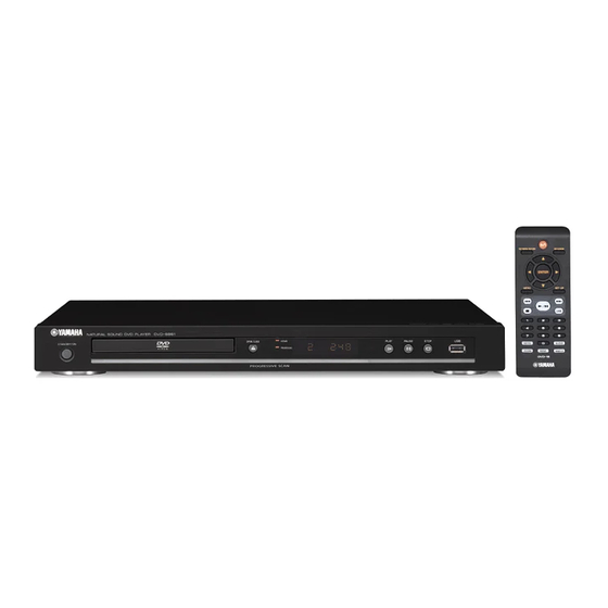
DVD-S661/DV-S6160 3 7 63 1515 0 I FRONT PANELS DVD-S661 (U, K, A, L, P models) DV-S6160 (U model) I REAR PANELS DVD-S661 (U model) L 13942296513 DVD-S661 (K model) DVD-S661 (A model) DVD-S661 (L model) u163 http://www.xiaoyu163.com... -
Page 6: Remote Control Panel
DVD-S661/DV-S6160 3 7 63 1515 0 DVD-S661 (P model) DV-S6160 (U model) I REMOTE CONTROL PANEL I SPECIFICATIONS PLAYBACK SYSTEM DVD Video, VR (Video Recording) format (DVD-RW) DVD-R, DVD-RW, DVD-R DL DVD+R, DVD+RW, DVD+R DL Video CD, SVCD PICTURE CD... - Page 7 DVD-S661/DV-S6160 3 7 63 1515 0 MULTIMEDIA (USB) APPLICATIONS Manufactured under license from Dolby Labo- ratories. “Dolby”, “Pro Logic” and the double-D Connections USB mass storage class device symbol are trademarks of Dolby Laboratories. Playback formats (USB device) “DTS” and “DTS Digital Out” are registered fs 32, 44.1, 48 kHz / 96, 128, 256,...
-
Page 8: Internal View
DVD-S661/DV-S6160 3 7 63 1515 0 I INTERNAL VIEW 1 AV P.C.B. MONO P.C.B. FRONT (4) P.C.B. 4 Power Supply Unit 5 DVD Mechanism 6 FRONT (2) P.C.B. 7 FRONT (1) P.C.B. 8 FRONT (3) P.C.B. L 13942296513 u163... -
Page 9: Repair Notes
DVD-S661/DV-S6160 3 7 6 3 1 5 1 5 0 I REPAIR NOTES I TRADE MODE None of the components of the following unit can be supplied separately. This unit provides TRADE mode which prevents the tray from opening even when the “OPEN/CLOSE” key is pressed. -
Page 10: Disassembly Procedures
DVD-S661/DV-S6160 3 7 6 3 1 5 1 5 0 I DISASSEMBLY PROCEDURES When disassembling, use T10 TORX screwdriver as shown below. See REPLACEMENT PARTS LIST for item numbers. Mounting Top Cover [240] 2.7 mm Remove 5 screws [250] (2 on sides and 3 on rear side). -
Page 11: Test Mode
DVD-S661/DV-S6160 3 7 6 3 1 5 1 5 0 I TEST MODE • Starting Test Mode a. Connect the power cable to the AC power outlet. b. Press the “STANDBY/ON” key while simultaneously pressing “PAUSE” and “STOP” keys of the main unit. -
Page 12: Block Diagram
DVD-S661/DV-S6160 3 7 6 3 1 5 1 5 0 I BLOCK DIAGRAM MONO • See page 20-22 → SCHEMATIC DIAGRAM • See page 23, 24 → SCHEMATIC DIAGRAM DIGITAL OUT COAXIAL 7301 HDMI TZA1039HL 38,39 +5VL 7108 +5STBY... -
Page 13: Wiring Diagram
DVD-S661/DV-S6160 3 7 6 3 1 5 1 5 0 I WIRING DIAGRAM 30FE-BT-VK-N 30FE-BT-VK-N 1100 1201 MCLK MCLK BCLK BCLK LRCLK LRCLK AC IN PCM_DATA0 PCM_DATA0 B4B-EH-A WH04D-1 PCM_DATA1 PCM_DATA1 1105 1522 PCM_DATA2 PCM_DATA2 SPDIF SPDIF CVBS CVBS... -
Page 14: Printed Circuit Boards
DVD-S661/DV-S6160 3 7 6 3 1 5 1 5 0 The first digit of a component indicates the component type. I PRINTED CIRCUIT BOARDS 1xxx : Connector 3xxx : Resistor 5xxx : Coil 7xxx : IC, Transistor, FET FOR INFORMATION ONLY (COMPONENT PARTS NOT AVAILABLE) - Page 15 DVD-S661/DV-S6160 3 7 6 3 1 5 1 5 0 The first digit of a component indicates the component type. 1xxx : Connector 3xxx : Resistor 5xxx : Coil 7xxx : IC, Transistor, FET 2xxx : Capacitor 4xxx : SMD jumper...
- Page 16 DVD-S661/DV-S6160 3 7 6 3 1 5 1 5 0 The first digit of a component indicates the component type. 1xxx : Connector 3xxx : Resistor 5xxx : Coil 7xxx : IC, Transistor, FET 2xxx : Capacitor 4xxx : SMD jumper...
- Page 17 DVD-S661/DV-S6160 3 7 6 3 1 5 1 5 0 The first digit of a component indicates the component type. 1xxx : Connector 3xxx : Resistor 5xxx : Coil 7xxx : IC, Transistor, FET 2xxx : Capacitor 4xxx : SMD jumper...
- Page 18 DVD-S661/DV-S6160 3 7 6 3 1 5 1 5 0 The first digit of a component indicates the component type. 1xxx : Connector 3xxx : Resistor 5xxx : Coil 7xxx : IC, Transistor, FET 2xxx : Capacitor 4xxx : SMD jumper...
- Page 19 DVD-S661/DV-S6160 3 7 6 3 1 5 1 5 0 The first digit of a component indicates the component type. 1xxx : Connector 3xxx : Resistor 5xxx : Coil 7xxx : IC, Transistor, FET 2xxx : Capacitor 4xxx : SMD jumper...
-
Page 20: Schematic Diagrams
DVD-S661/DV-S6160 3 7 6 3 1 5 1 5 0 The first digit of a component indicates the component type. I SCHEMATIC DIAGRAMS 1xxx : Connector 3xxx : Resistor 5xxx : Coil 7xxx : IC, Transistor, FET FOR INFORMATION ONLY (NO COMPONENT PARTS NOT AVAILABLE) - Page 21 DVD-S661/DV-S6160 3 7 6 3 1 5 1 5 0 The first digit of a component indicates the component type. 1xxx : Connector 3xxx : Resistor 5xxx : Coil 7xxx : IC, Transistor, FET 2xxx : Capacitor 4xxx : SMD jumper...
- Page 22 DVD-S661/DV-S6160 3 7 6 3 1 5 1 5 0 The first digit of a component indicates the component type. 1xxx : Connector 3xxx : Resistor 5xxx : Coil 7xxx : IC, Transistor, FET 2xxx : Capacitor 4xxx : SMD jumper...
- Page 23 DVD-S661/DV-S6160 3 7 6 3 1 5 1 5 0 The first digit of a component indicates the component type. 1xxx : Connector 3xxx : Resistor 5xxx : Coil 7xxx : IC, Transistor, FET 2xxx : Capacitor 4xxx : SMD jumper...
- Page 24 DVD-S661/DV-S6160 3 7 6 3 1 5 1 5 0 The first digit of a component indicates the component type. 1xxx : Connector 3xxx : Resistor 5xxx : Coil 7xxx : IC, Transistor, FET 2xxx : Capacitor 4xxx : SMD jumper...
- Page 25 DVD-S661/DV-S6160 3 7 6 3 1 5 1 5 0 The first digit of a component indicates the component type. 1xxx : Connector 3xxx : Resistor 5xxx : Coil 7xxx : IC, Transistor, FET 2xxx : Capacitor 4xxx : SMD jumper...
- Page 26 DVD-S661/DV-S6160 3 7 6 3 1 5 1 5 0 The first digit of a component indicates the component type. 1xxx : Connector 3xxx : Resistor 5xxx : Coil 7xxx : IC, Transistor, FET 2xxx : Capacitor 4xxx : SMD jumper...
- Page 27 DVD-S661/DV-S6160 3 7 6 3 1 5 1 5 0 MEMO MEMO 1 3 9 4 2 2 9 6 5 1 3 w w w u 1 6 3 MEMO MEMO http://www.xiaoyu163.com...
-
Page 28: Replacement Parts List
DVD-S661/DV-S6160 3 7 6 3 1 5 1 5 0 I REPLACEMENT PARTS LIST When disassembling, use T10 TORX screwdriver as shown below. 2.7 mm 250 251 3 x 6 S-Tight with brim 3 x 6 S-Tight Black 3 x 8 P-Tight Black... -
Page 29: Remote Control
DVD-S661/DV-S6160 3 7 6 3 1 5 1 5 0 WARNING I REMOTE CONTROL Components having special characteristics are marked Z and must be DVD-16 replaced with parts having specifications equal to those originally in- stalled. • PANEL • KEY NO. LAYOUT •... -
Page 30: Scene Control
DVD-S661/DV-S6160 3 7 6 3 1 5 1 5 0 I SCENE CONTROL • Example of connection RECEIVER/AMPLIFIER DVD/CD PLAYER (Model with SCENE function) (Model with SCENE control signal reception function) REMOTE CONTROL REMOTE CONTROL Monaural analog mini cable •...
Need help?
Do you have a question about the DVD-S661 and is the answer not in the manual?
Questions and answers