Yamaha DVD-S2700 Service Manual
Dvd audio/video sa-cd player
Hide thumbs
Also See for DVD-S2700:
- Owner's manual (348 pages) ,
- Owner's manual (90 pages) ,
- Owner's manual (51 pages)
Table of Contents
Advertisement
DVD AUDIO/VIDEO SA-CD PLAYER
DVD-S2700
This manual has been provided for the use of authorized YAMAHA Retailers and their service personnel.
It has been assumed that basic service procedures inherent to the industry, and more specifically YAMAHA Products, are already
known and understood by the users, and have therefore not been restated.
WARNING:
IMPORTANT:
The data provided is believed to be accurate and applicable to the unit(s) indicated on the cover. The research, engineering, and
service departments of YAMAHA are continually striving to improve YAMAHA products. Modifications are, therefore, inevitable
and specifications are subject to change without notice or obligation to retrofit. Should any discrepancy appear to exist, please
contact the distributor's Service Division.
WARNING:
IMPORTANT:
I CONTENTS
TO SERVICE PERSONNEL ...................................... 2-4
LOCALE MANAGEMENT INFORMATION ................... 4
FRONT PANEL .............................................................. 5
REAR PANELS .......................................................... 5-6
REMOTE CONTROL PANEL ........................................ 7
SPECIFICATIONS /
INTERNAL VIEW ........................................................... 8
1 0 1 0 3 8
Failure to follow appropriate service and safety procedures when servicing this product may result in personal
injury, destruction of expensive components, and failure of the product to perform as specified. For these reasons,
we advise all YAMAHA product owners that any service required should be performed by an authorized
YAMAHA Retailer or the appointed service representative.
The presentation or sale of this manual to any individual or firm does not constitute authorization, certification or
recognition of any applicable technical capabilities, or establish a principle-agent relationship of any form.
Static discharges can destroy expensive components. Discharge any static electricity your body may have
accumulated by grounding yourself to the ground buss in the unit (heavy gauge black wires connect to this buss).
Turn the unit OFF during disassembly and part replacement. Recheck all work before you apply power to the unit.
........................................ 7
8
8
2006
This manual is copyrighted by YAMAHA and may not be copied or
redistributed either in print or electronically without permission.
SERVICE MANUAL
IMPORTANT NOTICE
DISPLAY DATA ........................................................... 12
IC DATA ................................................................. 13-31
BLOCK DIAGRAM ....................................................... 32
WIRING DIAGRAM ...................................................... 33
PRINTED CIRCUIT BOARDS................................ 34-42
SCHEMATIC DIAGRAMS ...................................... 43-56
REPLACEMENT PARTS LIST .............................. 57-59
REMOTE CONTROL .................................................... 60
All rights reserved.
................... 8
............ 9-11
P.O.Box 1, Hamamatsu, Japan
'06.12
Advertisement
Table of Contents
Troubleshooting

Related Manuals for Yamaha DVD-S2700


Summary of Contents for Yamaha DVD-S2700
-
Page 1: Table Of Contents
This manual has been provided for the use of authorized YAMAHA Retailers and their service personnel. It has been assumed that basic service procedures inherent to the industry, and more specifically YAMAHA Products, are already known and understood by the users, and have therefore not been restated. -
Page 2: To Service Personnel
DVD-S2700 I TO SERVICE PERSONNEL 1. Critical Components Information AC LEAKAGE WALL EQUIPMENT TESTER OR Components having special characteristics are OUTLET UNDER TEST EQUIVALENT marked s and must be replaced with parts having specifications equal to those originally installed. 2. Leakage Current Measurement (For 120V Models... - Page 3 DVD-S2700 Laser Emitting conditions: 1) When the Top Cover is removed, and the STANDBY/ON SW is turned to the "ON" position, the laser component will emit a beam for several seconds to detect if a disc is present. During this time (5-10 sec.) the laser may radiate through the lens of the laser pick-up unit.
-
Page 4: Prevention Of Electrostatic Discharge
DVD-S2700 Warning for power supply The primary side of the power supply carries live mains voltage when the player is connected to the mains even when the player is switched off ! This primary area is not shielded so it is possible to touch copper tracks and/or components when servicing the player. -
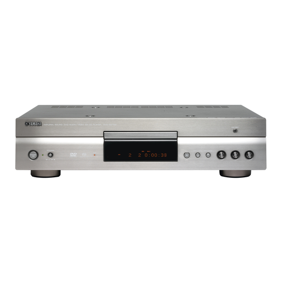
Page 5: Front Panel
DVD-S2700 I FRONT PANEL U, T, A, G, J models I REAR PANELS U model T model... - Page 6 DVD-S2700 A model G model J model...
-
Page 7: Remote Control Panel
DVD-S2700 I REMOTE CONTROL PANEL AUDIO FORMAT / GENERAL / Digital Dolby Digital/DTS/MPEG Dimensions (W x H x D) / 435 x 107 x 308.5 mm “HDMI”, the “HDMI” logo and “High Definition Compressed Digital (17-1/8" x 4-3/16" x 12-1/8") Multimedia Interface”... -
Page 8: Internal View
DVD-S2700 I INTERNAL VIEW I ERROR MESSAGE / Display / Cause / NO DISC When no disc is loaded in the tray. / UNKNOWN DISC When a disc which cannot be played or recognized is loaded in the tray. / POWER TRANSFORMER VIDEO (6) P.C.B. - Page 9 DVD-S2700 I DISASSEMBLY PROCEDURES Front panel ass'y (Remove parts in disassembly order as numbered.) Front side Disconnect the power cable from the AC outlet. 1. Removal of Top Cover a. Remove 4 screws (1), 4 screws (2) and 4 screws (3).
- Page 10 DVD-S2700 3. Removal of DVD Mechanism Unit 4. Electrostatic Protection of DVD Mechanism Unit a. Remove 4 screws (8). (Fig. 3) a. Remove 2 screws (9). (Fig. 4) b. Unlock CX16 and then disconnect the flexible flat cable, b. Lift the front of the cover DVD mechanism unit a little and ground the terminal face of the flexible flat cable and slide it to release the hook.
- Page 11 DVD-S2700 5. Removal of AUDIO P.C.B. 7. Removal of MAIN P.C.B. a. Remove 4 screws (0). (Fig. 3) a. Remove 6 screws (F). (Fig. 8) b. Remove 3 screws (A) and 1 screw (B). (Fig. 7) b. Remove CN11, CX12 and CX13. (Fig. 8) c.
-
Page 12: Troubleshooting / Disassembly Procedures / Display Data
DVD-S2700 I DISPLAY DATA G F401 : HCA14SM16 (AAX80850) G ANODE CONNECTION GR14 GR13 GR12 GR11 GR10 PATTERN AREA G PIN CONNECTION SG10 Pin No. 42 41 40 39 38 37 36 35 34 33 32 31 30 29 28 27 26... - Page 13 DVD-S2700 I IC DATA IC11: FLI2310LFCF (VIDEO P.C.B.) Digital video converter HSYNC1_PORT1 VSYNC1_PORT1 G/Y/Y_OUT_7 FIELD ID1_PORT1 G/Y/Y_OUT_6 IN_CLK1_PORT1 G/Y/Y_OUT_5 HSYNC2_PORT1 G/Y/Y_OUT_4 VSYNC2_PORT1 G/Y/Y_OUT_3 FIELD ID2_PORT1 G/Y/Y_OUT_2 VDD1 G/Y/Y_OUT_1 G/Y/Y_OUT_0 IN_CLK2_PORT1 VDD8 B/Cb/D1_0 R/V/Pr_OUT_7 B/Cb/D1_1 R/V/Pr_OUT_6 B/Cb/D1_2 R/V/Pr_OUT_5 B/Cb/D1_3 R/V/Pr_OUT_4 B/Cb/D1_4...
- Page 14 DVD-S2700 Internal Voltage Pull-up/ Pin Name I/O Type Drive Description Tolerance Pull-down HSYNC1_PORT1 Input Horizontal sync or reference - CTl1 of Port 1 VSYNC1_PORT1 Input Vertical sync or reference - CTL1 of Port 1 FIELD ID1_PORT1 Input Odd/Even field identification - CTL1 of Port 1...
- Page 15 DVD-S2700 Internal Voltage Pull-up/ Description Pin Name I/O Type Drive Tolerance Pull-down SDRAM DATA(11) Tristate I/O SDRAM data bus * VDD4 Power 3.3 V - Power pin for IO Ground Ground SDRAM DATA(12) Tristate I/O SDRAM data bus * SDRAM DATA(13)
- Page 16 DVD-S2700 Internal Voltage Pull-up/ Pin Name I/O Type Drive Description Tolerance Pull-down VSync1/CRef/VRef/Film indicator CTLOUT2 Tristate O/P Control signal output selectable as monitor Coast/HRef/VDD_en/HSync2 CTLOUT3 Tristate O/P Control signal output selectable as film Indicator/VRef/Backlight_en/VSync2 CTLOUT4 Tristate O/P Control signal output selectable as CRef/Field...
- Page 17 DVD-S2700 Internal Voltage Pull-up/ Pin Name I/O Type Drive Description Tolerance Pull-down Reserved Leave open R_VDD Power 3.3 V R_VSS Ground Ground Reserved Leave open Reserved Leave open Reserved Leave open R_VSS Ground Ground R_VDD Power 3.3 V R_VSS Ground...
- Page 18 DVD-S2700 IC13: ST72F321R (MAIN P.C.B.) Microprocessor No replacement part available. Device Block Diagram 8-BIT CORE PROGRAM MEMORY (16K - 60K Bytes) RESET CONTROL (512 - 2048 Bytes) WATCHDOG OSC1 OSC2 PA7:0 MCC/RTC/BEEP (8-bits) PORT A PORT F PORT B PF7:0...
-
Page 19: Ic Data
DVD-S2700 Pin no. Level Port Main Input Output function Pin Name Alternate function (afterreset) RTS_RS232 Port E4 CTS_RS232C Port E5 VFD_RESET Port E6 N.C. Port E7 EXT_SW1(RS232) Port B0 PWM output 3 N.C. Port B1 PWM output 2 DSP_RESET Port B2... - Page 20 DVD-S2700 IC15, 16: ADV7320KSTZ (VIDEO P.C.B.) Video decoder STANDARD DEFINITION ADV7320/ CONTROL BLOCK ADV7321 COLOR CONTROL BRIGHTNESS 12-BIT GAMMA PROGRAMMABLE FILTERS 12-BIT SD TEST PATTERN 12-BIT Y9–Y0 PROGRAMMABLE C9–C0 RGB MATRIX S9–S0 12-BIT HIGH DEFINITION 12-BIT CONTROL BLOCK HD TEST PATTERN...
- Page 21 DVD-S2700 Pin No Mnemonic Input/Output Description Power supply for digital inputs and outputs. SD or progressive scan/HDTV input port for Y data. Input port for interleaved progressive scan data. The LSB is set up on pin Y0. For 8-bit data input, LSB is set up on Y2.
- Page 22 DVD-S2700 Pin No Mnemonic Input/Output Description A 3040 ohm resistor must be connected from this pin to AGND and is used to control the SET2 amplitudes of the DAC outputs. COMP2 Compensation pin for DACs. Connect 0. 1 uF capacitor from COMP pin to V DAC_F In SD only mode: Chroma/Red/V analog output;...
-
Page 23: Dsd Decoder
DVD-S2700 IC20: SAA7893HLC2 (MAIN P.C.B.) DSD decoder to host host_sel HOST INTERFACE REGISTER SAA7893HL HOST INTERFACE MEMORY FRONT- PSP-KEY MANAGER DECODER INTERFACE PI-bus control 8-CHANNEL data-bus DECRYPTION/ DSD2PCM SECTOR CONVERSION DEMUX PROCESSOR SACD 2, 5 or 6-channel SPEAKER SETUP PI-BUS... - Page 24 DVD-S2700 Symbol Type Description Symbol Type[1] Description Pin. H_A[1] Address bus D_ADDR[3] SDRAM address bus H_DQ[15] I/O10 Data bus D_ADDR[4] SDRAM address bus H_DQ[14] I/O10 Data bus D_ADDR[2] SDRAM address bus GND_IO1 GND_IO GND I/O pads D_ADDR[5] SDRAM address bus...
- Page 25 DVD-S2700 IC35: ZR36778 (MAIN P.C.B.) MPEG decoder IR-RC Front Panel Receiver Concentrator SPI/I2C/GPIO/DDC TRAY 8/16 Mbits Flash MICROPROCESSOR SPINDLE SERVO 27 MHz SLED RESET Vaddis 32/64/128 Mbits SDRAM Disc loader RF amp Audio Servo amp S/PDIF 2 to 8 Stereo...
- Page 26 DVD-S2700 Pin Functions Direction Description SSCRXD SSC data input GPCI/O[17] General purpose I/O, monitored/controlled by the microprocessor or DSP or FCU SW PM[15] Probe mux data output MEMCS[1]# PNVM/SRAM chip select (active low) output GPCI/O[18] General purpose I/O, monitored/controlled by the microprocessor or DSP SW VDDP 3.3 V digital periphery power supply...
- Page 27 DVD-S2700 Pin Functions Direction Description FCUIF[16] Flash card interface unit output signal MEMDA[8] PNVM/SRAM bi-directional data bus FCUIF[21] Flash card interface unit I/O signal MEMAD[5] PNVM/SRAM address bus outputs FCUIF[15] Flash card interface unit output signal VDDP 3.3 V digital periphery power supply...
- Page 28 DVD-S2700 Pin Functions Direction Description RAMDAT[4] SDRAM bi-directional data bus VDDC 1.8 V digital core power supply RAMDAT[12] SDRAM bi-directional data bus GNDC Digital core ground of 1.8 V supply RAMDAT[3] SDRAM bi-directional data bus VDDP 3.3 V digital periphery power supply...
- Page 29 DVD-S2700 Pin Functions Direction Description COSYNC Composite sync output / Active only when component analog output is selected ICGPCI/O[1] General purpose I/O, monitored/controlled by the microprocessor or DSP SW When input, the pin can be used as general purpose external interrupt to the microprocessor VDDP 3.3 V digital periphery power supply...
- Page 30 DVD-S2700 Pin Functions Direction Description When the Vaddis 778 outputs composite SCART video, this line is the Y output VDDDAC 3.3 V analog power supply for the video DACs Y/R/V When the Vaddis 778 outputs composite non-SCART video, this line is Y output...
- Page 31 DVD-S2700 Pin Functions Direction Description PWMCO[6] PMW8 output signal IDGPCI/O[4] General purpose I/O, monitored/controlled by the microprocessor or DSP SW When input, the pin can be used as general purpose external interrupt to the DSP FCUIF[32] Flash card interface unit I/O signal...
-
Page 32: Block Diagram
DVD-S2700 I BLOCK DIAGRAM VIDEO (1) MAIN JK12 IC21 • See page 43-47 → SCHEMATIC DIAGRAM • See page 48-53 → SCHEMATIC DIAGRAM COMPONENT IC15 1,3,5 JK13 42,43,44 9,11,13 X101 IC20 D1/D2 J model IC26 JK11 X102 IC36 IC24 2,4,6... -
Page 33: Wiring Diagram
DVD-S2700 I WIRING DIAGRAM VIDEO (5) POWER TRANSFORMER VIDEO (6) VIDEO (1) (G model) SCART_R MAIN SCART_L G model CN12 (3P) DVD MECHANISM UNIT BN13 (3P) POWER SUPPLY UNIT AUDIO DVD MECHANISM UNIT VIDEO (3) VIDEO (4) DVD MECHANISM UNIT... -
Page 34: Printed Circuit Boards
DVD-S2700 I PRINTED CIRCUIT BOARDS When any part not included in the replacement parts list has failed, replace the P.C.B.. VIDEO (1) VIDEO (1) AUDIO AUDIO (CY13) (CY12) (CY11) (CY12) MAIN P.C.B. (Top view) U model DVD MECHANISM UNIT VIDEO (5) - Page 35 DVD-S2700 MAIN P.C.B. (Bottom view) U model...
- Page 36 DVD-S2700 VIDEO OUT COMPONENT VIDEO / S-VIDEO VIDEO (1) P.C.B. D1/D2 AV (SCART) HDMI (Top view) J model G model AUDIO (BN13) G model U model G model G model MAIN (CX13) MAIN (CX12) POWER SUPPLY UNIT (CN96)
- Page 37 DVD-S2700 VIDEO (1) P.C.B. (Bottom view) G model...
- Page 38 DVD-S2700 VIDEO (2) P.C.B. (Top view) HDMI MAIN (CX11) VIDEO (2) P.C.B. (Bottom view) VIDEO (3) P.C.B. VIDEO (3) P.C.B. VIDEO (4) P.C.B. VIDEO (4) P.C.B. (Top view) (Bottom view) (Top view) (Bottom view) AUDIO DIRECT STANDBY STANDBY/ON...
- Page 39 DVD-S2700 VIDEO (5) P.C.B. (Top view) VIDEO (6) P.C.B. VIDEO (6) P.C.B. (Top view) (Bottom view) REMOTE CONTROL RS232C ON/OFF IN/OUT POWER TRANSFORMER MAIN (CX14) VIDEO (5) P.C.B. (Bottom view) AUDIO (CN12)
- Page 40 DVD-S2700 AUDIO P.C.B. (Top view) MAIN VIDEO (6) (CX15) (CN91) COAXIAL / DIGITAL OPTICAL MAIN (CX17) MIXED 2CH FRONT AUDIO OUT CENTER / SUBWOOFER SURROUND VIDEO (1) (CN12) G model...
- Page 41 DVD-S2700 AUDIO P.C.B. (Bottom view)
- Page 42 DVD-S2700 POWER SUPPLY UNIT (Top view) POWER TRANSFORMER AC IN VIDEO (1) (CN15) POWER MAIN (CN11) ON/OFF...
-
Page 43: Schematic Diagrams
DVD-S2700 I SCHEMATIC DIAGRAMS When any part not included in the replacement parts list has failed, replace the P.C.B.. MAIN 1/5 Page 54 Page 56 Page 48 Page 48 to VIDEO (2)_CY81 to POWER SUPPLY UNIT_CN95 to VIDEO (1)_CY12 to VIDEO (1)_CY13... - Page 44 DVD-S2700 MAIN 2/5 Page 55 to AUDIO_CY11...
- Page 45 DVD-S2700 MAIN 3/5...
- Page 46 DVD-S2700 MAIN 4/5 U model T, A, G, J models U model...
- Page 47 DVD-S2700 MAIN 5/5...
- Page 48 DVD-S2700 VIDEO 1/7 VIDEO (1) Page 43 to MAIN_CX12 Page 43 to MAIN_CX13...
- Page 49 DVD-S2700 VIDEO 2/7 VIDEO (1) Page 56 to POWER SUPPLY UNIT_CN96...
- Page 50 DVD-S2700 VIDEO 3/7 VIDEO (1) G model...
- Page 51 DVD-S2700 VIDEO 4/7 VIDEO (1) U model VIDEO S-VIDEO D1/D2 (J model)
- Page 52 DVD-S2700 VIDEO 5/7 VIDEO (1) G model Page 56 to AUDIO_BN13...
- Page 53 DVD-S2700 VIDEO 6/7 VIDEO (1) MICROPROCESSOR HDMI...
- Page 54 DVD-S2700 VIDEO 7/7 VIDEO (2) VIDEO (6) POWER TRANSFORMER VIDEO (3) AUDIO DIRECT LED HDMI LED Connected: Green Unconnected: Orange VIDEO (4) STANDBY/ON LED Page 55 to AUDIO_CN12 Page 56 to POWER SUPPLY UNIT_CN92 STANDBY/ON Green STANDBY: Orange VIDEO (5)
- Page 55 DVD-S2700 AUDIO OPTICAL DIGITAL COAXIAL Page 44 to MAIN_CX15 Page 52 to VIDEO (1)_CN12 (G model) MIXED 2CH FRONT Page 47 to MAIN_CX17 AUDIO OUT SUBWOOFER / CENTER SURROUND Page 54 to VIDEO (6)_CN91...
- Page 56 DVD-S2700 POWER SUPPLY UNIT POWER ON /OFF To POWER TRANSFORMER Page 49 to VIDEO (1) _CN15 AC IN Page 43 to MAIN_CN11...
-
Page 57: Replacement Parts List
DVD-S2700 I REPLACEMENT PARTS LIST P.C.B. MAIN, P.C.B. VIDEO and P.C.B. AUDIO • ELECTRICAL COMPONENT PARTS Note) When any part not included in the replacement parts list has failed, replace the P.C.B.. WARNING G Components having special characteristics are marked s and must be replaced with parts having specifications equal to those originally installed. - Page 58 DVD-S2700 • OVERALL ASS’Y G model J model 10 (1) 10 (1) * Note) The replacement battery cover is not available. 10 (5) 10 (6) 10 (4) 5 (1) 10 (1) 10 (3) * Note) Precaution when replacing the foot...
- Page 59 DVD-S2700 ✻ New Parts ✻ New Parts...
-
Page 60: Remote Control
DVD-S2700 I REMOTE CONTROL • SCHEMATIC DIAGRAM • PANEL • KEY NO. LAYOUT • KEY CODE Key no. Function Custom code OSC1 LIGHT – POWER 7C-F6 455kHz DIMMER 7C-A9 HDMI 7C-E5 AUDIO DIRECT 7C-D9 OSC2 STANDBY 7C-F7 K11 K12 K13 K14... - Page 61 DVD-S2700 MEMO MEMO...
- Page 62 DVD-S2700...
Need help?
Do you have a question about the DVD-S2700 and is the answer not in the manual?
Questions and answers