Table of Contents

Related Manuals for Ford FG3050P


Summary of Contents for Ford FG3050P
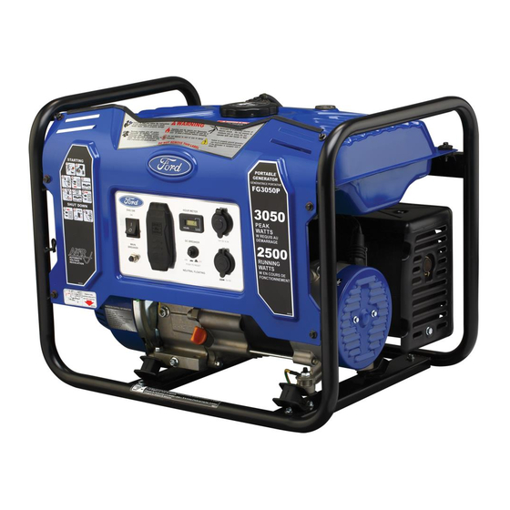
- Page 1 MODEL#: FG3050 P ITEM#: F2E250R991 Generator OPERATOR’S MANUAL Warning: The Engine Exhaust from this product contains chemicals known to the State of California to cause cancer, birth defects or other reproductive harm. www.fordpower.cc...
-
Page 2: Table Of Contents
TABLE OF CONTENTS Introduction..................................... 3 Product Specifications..............................3 Parts Ordering / Customer Service..........................3 Safety Rules.................................... 4 Safety Symbols................................4 Safety Instructions............................... 4 Features....................................7 Assembly....................................9 Unpacking..................................9 Packing List................................Adding Oil..................................9 Adding Fuel................................10 Connecting Generator to an Electrical System......................10 Operation....................................11 Grounding the Generator............................11 How to Start Engine.............................. -
Page 3: Introduction
INTRODUCTION Thank you for purchasing this superior quality portable generator from Ford Power Equipment. When operating and maintaining this product as instructed in this manual, your generator will give you many years of reliable service. Product Specifications: This generator is an engine-driven, revolving field, alternating current (AC) portable generator. It is designed to supply electrical power to operate tools, appliances, camping equipment, lighting, or serve as a back up power source during power outages. -
Page 4: Safety Rules
SAFETY RULES Safety Symbols Indicates a potentially hazardous WARNING! situation which could result in serious injury or death if not avoided. Indicates a potentially hazardous CAUTION! situation which could result in damage to equipment or property. Toxic Fumes Risk of fire Risk of explosion Risk of electric shock Hot surface... - Page 5 SAFETY RULES Never exceed generator’s wattage / amperage capacity. This could damage the generator WARNING! and / or connected electrical devices. Check operating voltage and frequency requirements of all electrical devices prior to plugging them into the generator. • Never start or stop engine with electrical devices plugged in to the receptacles. Failure to do WARNING! so could damage the generator and / or connected electrical devices.
- Page 6 Never transport or make adjustments to this unit while it is running. • Never insert objects through cooling slots. Never operate this unit if there are any broken or missing parts and only use Ford Power WARNING! Equipment replacement parts specifically designed for this unit.
-
Page 7: Features
FEATURES A - ON/OFF Switch Circuit Protector B - Hour Meter Volt AC 20 Amp duplex Receptacle (NEMA 5-20R). C - 12 DC Cigarette Lighter Receptacle D - USB (Dual Port) - Page 8 FEATURES M - Fuel Tank G - Fuel Gauge H - Fuel Tank Vapor Vent N - Fuel Fill Cap I - Generator Frame O - Fuel Valve (ON/OFF) J - Choke Lever P - Recoil Starter Grip K - Air Filter Q - Oil Fill (Dipstick) L - Oil Drain Plug...
-
Page 9: Assembly
ASSEMBLY Unpacking 1. Place box on a level surface. 2. Remove all items from box except the generator. Make sure all items listed on the packing list are included and not damaged. 3. Cut down the sides of the box being careful to avoid hitting the generator. Packing List Check all loose parts to the following list. -
Page 10: Adding Fuel
ASSEMBLY Adding Fuel (See fig 4) • Set generator on a clean and level surface in an area that is well ventilated. • Remove fuel cap. • Insert a funnel into the fuel tank and carefully pour gasoline into the tank until fuel level reaches 1 ½ inches below the top of the neck. -
Page 11: Operation
OPERATION Grounding the Generator (See fig 5) The ground terminal located on the back of the generator frame must always be used to connect generator to a driven ground rod. Connect the ground terminal to the driven ground rod with a No 8 AWG (American Wire Gauge) copper wire. The wire connects to the terminal between the lock washer and nut. -
Page 12: How To Stop Engine
OPERATION Never start or stop engine with electrical devices plugged in to the receptacles. Failure to WARNING! do so could damage the generator and / or connected electrical devices. • Always start the engine and let it stabilize before connecting any electronic devices. •... -
Page 13: Don't Overload Generator
OPERATION CAUTION! Do not move the voltage selector switch while powering electrical devices. Disconnect all electrical loads before moving the switch. Failure to disconnect electrical loads could damage the switch or generator. CAUTION! Do not connect 3-phase loads to generator. Extension Cord Selection Refer to the below table to ensure the extension cord used has the capacity to carry the required load. -
Page 14: Wattage Reference Guide
OPERATION Operating voltage and frequency requirement of all electronic equipment should be checked prior to plugging them into this generator. Damage may result if the equipment is not designed to operate within a +/- 10% voltage variation, and +/- 3 Hz frequency variation from the generator name plate ratings. To reduce the risk of damage, always have an additional load plugged into the generator if solid state equipment (such as television set) is used. -
Page 15: Cold Weather Operation
OPERATION Never exceed generator’s wattage / amperage capacity. This could damage the generator WARNING! and / or connected electrical devices. Check operating voltage and frequency requirements of all electrical devices prior to plugging them into the generator. • Hour Meter (See Fig 13) The digital hour meter operates whenever the engine is running and keeps track of how many hours the unit has been used. -
Page 16: Maintenance
MAINTENANCE Creating a Temporary Cold Weather Shelter In an emergency, the original shipping carton can be used as a temporary shelter. The shelter should hold enough heat created by the generator to prevent icing. Cut off all flaps. Cut off one of the long sides of the carton to expose the units muffler and exhaust. Do not enclose the muffler / exhaust side of the generator. -
Page 17: Engine Maintenance
MAINTENANCE Changing Oil (See Fig 14) • Run the Generator until the Engine is warm. • Place generator on a level surface. • Remove the crankcase dipstick. • Place an oil pan underneath the oil drainage bolt to collect used oil. Oil Fill &... -
Page 18: Air Filter
MAINTENANCE Used oil should be disposed of at an approved disposal site. See your local oil retailer for CAUTION! more information. Air Filter (See Fig 15) A dirty air filter will reduce the life span of the engine, make it difficult to start the engine, and reduce the unit’s performance. •... -
Page 19: Maintaining Fuel Valve
MAINTENANCE Carburetor Adjustment The carburetor is low emission and is equipped with a non-adjustable idle mixture valve. If adjustment is needed contact an authorized dealer. Replacing Fuel Filter (See Fig 18) Occasionally the fuel filter may become clogged and need replacing. To purchase a replacement fuel filter contact PULSAR customer service or your local small Engine repair shop. -
Page 20: How To Store
MAINTENANCE Draining the carburetor • Turn the engine OFF. • Turn the fuel valve to the OFF position. • Position a suitable container under the carburetor drain screw to catch fuel; loosen the screw. • Allow fuel to drain completely into container. •... -
Page 21: Troubleshooting
TROUBLESHOOTING Problem Cause Solution Engine is running, but AC output is not 1. Open circuit breaker 1. Reset circuit breaker available 2. Poor connection 2. Check and repair 3. Defective cord set 3. Check and repair 4. Connected device is faulty 4. -
Page 22: Diagrams
DIAGRAMS... -
Page 23: Warranty
From the date of original purchase, Ford Power Equipment warrants to the original purchaser that each portable generator sold, shall be free from defect in material and workmanship for the items and time period set forth below. Ford Power Equipment, at its discretion, agrees to repair or replace any defective part that upon examination, inspection, and testing by a Ford Power Equipment authorized service dealer, is found to be defective within the original warranty period. - Page 24 Take the original receipt and product to the place of purchase or mail the original receipt and product to the address found on the web site if purchased on-line. You can also locate your nearest Ford Power Equipment dealer for service or warranty questions by calling toll free at 1-888-863-7589.
Need help?
Do you have a question about the FG3050P and is the answer not in the manual?
Questions and answers