
Related Manuals for Ford FG2500iS


Summary of Contents for Ford FG2500iS
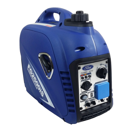
- Page 1 Model: FG2500iS FG2500iSE Inverter Generator OPERATOR’S MANUAL ORIGINAL INSTRUCTIONS LICENCED BY: PULSAR PRODUCTS INC 2051 S Lynx Place, Ontario, California, U.S.A 91761...
-
Page 2: Table Of Contents
TABLE OF CONTENTS Introduction . N NNNNNNNNNNNNNNNNNNNNNNNNNNNNNNNNNNNNNNNNNNNNNNNNNNNNNNNNNNNNNNNNNNNNNNNNNNNNNNNNNNNNNNNNNNNNNNNNNNNNNNNNNNNNNNNNNNNNNNNNNNNNNNNNNNNNNNNNNNNNNNNNNNNNNNNNNNNNNNNNNNNNNNNNNN 3 Safety Rules . N NNNNNNNNNNNNNNNNNNNNNNNNNNNNNNNNNNNNNNNNNNNNNNNNNNNNNNNNNNNNNNNNNNNNNNNNNNNNNNNNNNNNNNNNNNNNNNNNNNNNNNNNNNNNNNNNNNNNNNNNNNNNNNNNNNNNNNNNNNNNNNNNNNNNNNNNNNNNNNNNNNNNNNN 4 Safety Symbols . NNNNNNNNNNNNNNNNNNNNNNNNNNNNNNNNNNNNNNNNNNNNNNNNNNNNNNNNNNNNNNNNNNNNNNNNNNNNNNNNNNNNNNNNNNNNNNNNNNNNNNNNNNNNNNNNNNNNNNNNNNNNNNNNNNNNNNNNNNNNNNNNNNNNNNNNN 4 Safety Instructions . NNNNNNNNNNNNNNNNNNNNNNNNNNNNNNNNNNNNNNNNNNNNNNNNNNNNNNNNNNNNNNNNNNNNNNNNNNNNNNNNNNNNNNNNNNNNNNNNNNNNNNNNNNNNNNNNNNNNNNNNNNNNNNNNNNNNNNNNNNNNNNNNNNN 4 Features . NNNNNNNNNNNNNNNNNNNNNNNNNNNNNNNNNNNNNNNNNNNNNNNNNNNNNNNNNNNNNNNNNNNNNNNNNNNNNNNNNNNNNNNNNNNNNNNNNNNNNNNNNNNNNNNNNNNNNNNNNNNNNNNNNNNNNNNNNNNNNNNNNNNNNNNNNNNNNNNNNNNNNNNNNNNNNNNN 7 Control Panel Functions . N NNNNNNNNNNNNNNNNNNNNNNNNNNNNNNNNNNNNNNNNNNNNNNNNNNNNNNNNNNNNNNNNNNNNNNNNNNNNNNNNNNNNNNNNNNNNNNNNNNNNNNNNNNNNNNNNNNNNNNNNNNNNNNNNNNNNNNNNNNNNNNNNNNN 8 ON/OFF Start Switch and Choke. N NNNNNNNNNNNNNNNNNNNNNNNNNNNNNNNNNNNNNNNNNNNNNNNNNNNNNNNNNNNNNNNNNNNNNNNNNNNNNNNNNNNNNNNNNNNNNNNNNNNNNNNNNNNNNNNNNNNNNNNNNNNN 8 NNNNNNNNNNNNNNNNNNNNNNNNNNNNNNNNNNNNNNNNNNNNNNNNNNNNNNNNNNNNNNNNNNNNNNNNNNNNNNNNNNNNNNNNNNNNNNNNNNNNNNNNNNNNNNNNNNNNNNNNNNNNNNNNNNNNNNNNNNNNNNNNNNNNNNNNNNNNNNN... - Page 3 INTRODUCTION Thank you for purchasing this superior quality portable generator from Ford Power Equipment. When operating and maintaining this product as instructed in this manual, your generator will give you many years of reliable service. This generator is an engine-driven, portable generator.It is designed to supply electrical power to operate tools, appliances, camping equipment, lighting, or serve as a back up power source during power outages.
-
Page 4: Safety Rules
SAFETY RULES Safety Symbols Indicates a potentially hazardous situation which could result in serious injury or death if not avoided. Indicates a potentially hazardous situation which could result in damage to equipment or property. Injury of damage Read manual before use Wear noise protection Toxic fumes Risk of fire... - Page 5 SAFETY RULES Engine exhaust contains chemicals that lead to cause cancer and birth defects. • Always wash hands after handling generator. To reduce the risk of serious injury, avoid attempting to lift the generator alone. Never exceed generator’s wattage / amperage capacity. This could damage the generator and / or connected electrical devices.
- Page 6 Never transport or make adjustments to this unit while it is running. • Never insert objects through cooling slots. Never operate this unit if there are any broken or missing parts and only use Ford Power Equipment replacement parts specifically designed for this unit. •...
-
Page 7: Features
FEATURES Q - Parallel Outlets A - Spark Plug Cover I - Control Panel R - Ground Terminal B - Spark Arrestor J - Oil Warning Light S - 12V DC Port K - Overload Indicator Light T - Thermal protector D - Outer Casing (Side Panel) L - AC Pilot Light E - Handle (Grip) -
Page 8: Control Panel Functions
CONTROL PANEL FUNCTIONS ON/OFF Start Switch and Choke Start Switch “OFF” When the Start Switch is in the “OFF” position the fuel valve is O FF switched off and the engine will not run. Start Switch “CHOKE” When the Start Switch is in the “CHOKE” position the fuel valve is switched on and the engine can be started. -
Page 9: Ac Pilot Indicator Light
CONTROL PANEL FUNCTIONS Note: The engine overload indicator light may turn on for a few sec- onds when attaching a load due to a power surge. This is normal. AC Pilot Indicator Light The green AC Pilot Indicator Light comes on when the engine starts and generates power. -
Page 10: Parallel Outlets
This operation requires special cables. When operating parallel generators, the rated output is 4.0kVA and the rated current is 17.4A / 230V AC. For cables and instructions consult a FORD dealer for a PARALLEL OPERATION C C C A A A B B B L L L E E E K K K I I I T T T . . . -
Page 11: Assembly
ASSEMBLY Connecting Generator to an Electrical System • If connecting generator to a building’s electrical system for standby power, The power from the generator must be isolated from the circuit breaker or alternative power source. The connection must comply with all electrical codes and applicable laws. -
Page 12: Adding / Checking Oil
ASSEMBLY Adding / Checking Engine Oil • Place generator on a level surface. • Remove screws and then remove the outer casing cover. • Remove the crankcase dipstick. • Insert a funnel into the crankcase dipstick hole and carefully add the specified amount of 4-Cycle engine oil (SAE 10W- 30) to empty reservoir until or oil reaches the outer edge of the oil fill hole (crankcase dipstick hole). -
Page 13: Operation
OPERATION Grounding the Generator To avoid electrocution, this generator must be properly grounded prior to use. For instructions see Control Panel Functions on page 10. How to Start Engine • Place generator on a level surface. All electrical loads MUST be disconnected from generator. •... -
Page 14: How To Stop Engine
OPERATION How to Stop Engine • Turn the Economy switch to the “OFF” position. • Disconnect any electronic device. All loads MUST be disconnect from the generator. Never start or stop the engine with electrical devices plugged in to the receptacles. •... -
Page 15: Charging A 12 Volt Battery
OPERATION Charging a 12 Volt Battery This generator can be used to charge a 12 volt automotive or storage battery by taking the following steps: ONLY level is low. Never add tap water. 1. Use a wire brush to clean battery terminals if corroded. 2. -
Page 16: Ac Parallel Operation
OPERATION AC Parallel Operation It is possible to connect two FG2500iS generators to each other, using a parallel cable kit, to increase available power output. • Connect PARALLEL OPERATION CABLES to two FG2500iS generators according to the instructions provided with the cable kit. -
Page 17: Don't Overload Generator
OPERATION Don’t Overload Generator Make sure you can supply enough rated watts for all electronic devices connected to the generator. Rated watts refer to the power a generator must supply to keep a device running. Surge watts refer to the power a generator must supply to start an electronic device. -
Page 18: Maintenance
Before inspecting or servicing this machine, make sure the engine is off and no parts are WARNING! moving. Disconnect the spark plug wire and move it away from the spark plug. If you are unsure of how to perform a maintenance task, have the unit serviced by a FORD CAUTION! dealer CAUTION! Only use specified PULSAR replacement partsN... -
Page 19: Checking Spark Plug
MAINTENANCE Checking Spark Plug • Remove cap. Then remove spark plug cap. • Disconnect the spark plug wire from the spark plug. • Before removing the spark plug, clean the area around its base to prevent debris from entering the engine. •... -
Page 20: Changing Oil
MAINTENANCE Changing Oil • Place generator on a level surface. • Run the generator for several minutes until the engine is warm. Turn off generator. • Remove screws, then remove outer casing side cover. • Remove the crankcase dipstick. • Place an oil pan underneath the engine. -
Page 21: Air Filter
• Remove screws, then remove the muffler cover as shown. • • • Check the muffler screen and spark arrester for damage. If damaged replace with FORD replacement parts • • • Install the outer casing and tighten the screws. -
Page 22: Fuel Filter
MAINTENANCE Fuel Tank Filter • • • • • Install fuel cap. Fuel Filter • To clean, remove screws, remove outer casing, and drain fuel. • Lift and hold onto the clamp, then remove hose from tank. • • • •... - Page 23 MAINTENANCE Contact with a hot engine or exhaust system can cause serious burns or fires. Let the engine cool WARNING! before transporting or storing the generator. Take care not to drop or strike the generator when transporting. Do not place heavy objects on the CAUTION! generator.
-
Page 24: Troubleshooting
9. Add oil level. 10. Engine has flooded 10. Wait 5 minutes and recrank engine 11. Faulty ignition 11. Contact FORD dealer 1. See P.17 “Don’t overload generator” 1. Generator is overloaded Engine lacks power 2. Clean or replace fuel filter 2.Clogged fuel filter... -
Page 25: Wiring Diagarm
WIRING DIAGRAM... - Page 26 WIRING DIAGRAM...
-
Page 27: Noise
This information, however, will enable the user of the machine to make a better evaluation of the hazard and risk. Measured according with ISO8528-10, ISO 3744 and Noise Directive 2000/14/EC. MODEL FG2500iS Emission sound pressure level at the 68 dB(A) operator’s operation (according with... -
Page 28: Service
SERVISE WARRANTY: Please see the separate sheet in accessories. CE DECLARATION: Please see the separate sheet in accessories. HOW TO CONTACT US: To order parts, receive warranty assistance, or other services inquiries, please see the warranty sheet. Record the following information bellow for service or warranty assistance. Date of Purchase: Model Number: Series Number:...
Need help?
Do you have a question about the FG2500iS and is the answer not in the manual?
Questions and answers