Advertisement
Quick Links
INSTALLATION AND MAINTENANCE INSTRUCTIONS
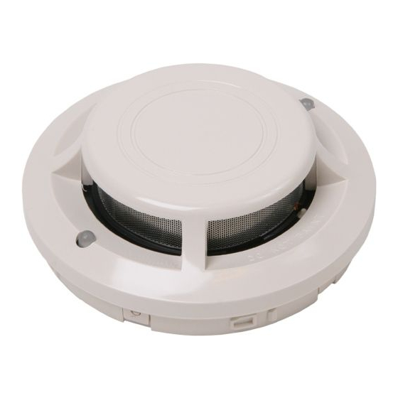
7251A Intelligent Laser Smoke Sensor
Specifications
Operating Voltage Range:
Standby Current:
Max. Alarm Current (LED on:)
Operating Humidity Range:
Operating Temperature Range:
Height:
Diameter:
Weight:
Additional Bases Available:
Before Installing
This sensor must be installed in compliance with the con-
trol panel system installation manual. The installation must
meet the requirements of the Authority Having Jurisdiction
(AHJ). Sensors offer maximum performance when installed
in compliance with CAN/ULC S524.
General Description
Model 7251A is a plug-in type smoke sensor that uses a
laser based sensing chamber. The sensor uses analog-
addressable communications to transmit smoke density
and other information to the control panel. Rotary-decade
switches are provided for setting the sensor's address. Two
LEDs on the sensor are controlled by the panel to indicate
sensor status. An output is provided for connection to an
optional remote LED annunciator (P/N RA400Z).
This detector requires compatible addressable com-
munications to function properly. Connect this sensor
to listed-compatible control panels only.
Spacing
System Sensor recommends spacing sensors in compli-
ance with CAN/ULC S524. In low air flow applications with
smooth ceilings, space sensors 30 feet apart. For spe-
cific information regarding sensor spacing, placement, and
special applications, refer to CAN/ULC S524 or the System
Sensor Guide For Proper Use of System Smoke Detectors,
available from System Sensor (P/N I56-407-XX).
Wiring Instructions
D200-09-00
15 to 32 VDC
330µA @ 24 VDC (one communication every 5 sec. with LED blink enabled)
6.5 mA @ 24 VDC
10% to 93% Relative Humidity, noncondensing
0°C to 38°C (32°F to 100°F)
1.7 inches (43 mm) installed in B210LPA Base
6.1 inches (155 mm) installed in B210LPA Base
4.1 inches (104 mm) installed in B501A Base
5.0 oz. (142 g)
All 200/500 Series bases are compatible.
6581 Kitimat Rd., Unit #6, Mississauga, Ontario, L5N 3T5
All wiring must be installed in compliance with the Canadian
Electrical Code, applicable local codes, and any special
requirements of the Authority Having Jurisdiction. Proper
wire gauges should be used. The installation wires should
be color-coded to limit wiring mistakes and ease system
troubleshooting. Improper connections will prevent a sys-
tem from responding properly in the event of a fire.
Remove power from the communication line before
installing sensors.
All wiring must conform to applicable local codes, ordi-
nances, and regulations.
1. Wire the sensor base (supplied separately) per the wir-
ing diagram, see Figure 1.
2. Set the desired address on the sensor address switch-
es, see Figure 2.
3. Install the sensor into the sensor base. Push the sensor
into the base while turning it clockwise to secure it in
place.
4. After all sensors have been installed, apply power to the
control unit and activate the communication line.
5. Test the sensor(s) as described in the TESTING section
of this manual.
1
1-800-SENSOR2, FAX: 905-812-0771
www.systemsensor.ca
I56-1986-000
Advertisement

Related Manuals for System Sensor 7251A


Summary of Contents for System Sensor 7251A
- Page 1 INSTALLATION AND MAINTENANCE INSTRUCTIONS 6581 Kitimat Rd., Unit #6, Mississauga, Ontario, L5N 3T5 1-800-SENSOR2, FAX: 905-812-0771 7251A Intelligent Laser Smoke Sensor www.systemsensor.ca Specifications Operating Voltage Range: 15 to 32 VDC Standby Current: 330µA @ 24 VDC (one communication every 5 sec. with LED blink enabled) Max. Alarm Current (LED on:) 6.5 mA @ 24 VDC Operating Humidity Range: 10% to 93% Relative Humidity, noncondensing Operating Temperature Range: 0°C to 38°C (32°F to 100°F) Height: 1.7 inches (43 mm) installed in B210LPA Base Diameter: 6.1 inches (155 mm) installed in B210LPA Base 4.1 inches (104 mm) installed in B501A Base Weight: 5.0 oz. (142 g) Additional Bases Available: All 200/500 Series bases are compatible. Before Installing All wiring must be installed in compliance with the Canadian This sensor must be installed in compliance with the con- Electrical Code, applicable local codes, and any special requirements of the Authority Having Jurisdiction. Proper...
- Page 2 Figure 1. Wiring diagram: CAUTION Do not loop wire under terminal 1 or 2. Break RE M OTE ANNUN C IATOR wire run to provide supervision of connection. – – – OPTIONAL RETURN LOOP C0100-00 shown in Figure 3. CAUTION 2. The sensor should alarm the panel. Dust covers provide limited protection against airborne Two LEDs on the sensor are controlled by the panel dust particles during shipping. Dust covers must be to indicate sensor status. Coded signals, transmitted removed before the sensors can sense smoke. Remove from the panel, can cause the LEDs to blink, latch sensors prior to heavy remodeling or construction.
- Page 3 Figure 2. Rotary decade address switches: Cleaning It is recommended that the detector be removed from its mounting base to facilitate cleaning. The detector is cleaned as follows: NOTE: Before removing the detector, notify the proper authorities that the smoke detector system is undergoing maintenance and will be temporarily out of service. Disable the zone or system under- going maintenance to prevent unwanted alarms.
- Page 4 Laser Safety Information CAUTION This smoke detector does not produce any hazardous Use of controls, adjustments, or performance of proce- laser radiation and is certified as a Class 1 laser product under the U.S. Department of Health and Human Services dures other than those specified in this manual may result in hazardous radiation exposure. (DHHS) Radiation Performance Standard according to the Radiation Control for Health and Safety Act of 1968. Special Note Regarding Smoke Detector Guards Any radiation emitted inside the smoke detector is com- Smoke detectors are not to be used with detector guards pletely within the protective housings and external covers.
Need help?
Do you have a question about the 7251A and is the answer not in the manual?
Questions and answers