Table of Contents
Advertisement
Quick Links
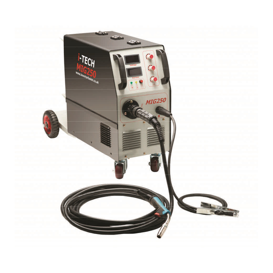
i-TECH
MIG250
Inverter MIG
Welding Machine
User Manual
Do not a empt to set up or operate this equipment un l you have read and fully
understood the contents of this manual. If you do not fully understand any of the
instruc ons, please contact your supplier for further informa on and advice
before beginning any welding procedure.
Advertisement
Table of Contents

Related Manuals for Inverter Fusion i-TECH MIG250


Summary of Contents for Inverter Fusion i-TECH MIG250
- Page 1 i-TECH MIG250 Inverter MIG Welding Machine User Manual Do not a empt to set up or operate this equipment un l you have read and fully understood the contents of this manual. If you do not fully understand any of the instruc ons, please contact your supplier for further informa on and advice before beginning any welding procedure. ...
-
Page 2: Table Of Contents
Contents 1. General descrip on ..................... 1 2. Warranty ...................... 2 3. Safety ........................ 2 4. Main parameters .................... 3 5. Panel layout ...................... 4 6. Set up & opera on .................... 6 7. Welding Guide .................... 8 8. Cau on ...................... 12 9. Maintenance ..................... 12 10. Troubleshoo ng .................... 13 1. General Descrip on The i‐TECH MIG250 welding machine is manufactured with advanced inverter technology ... -
Page 3: Warranty
2. Warranty 1. Your i‐TECH MIG250 welder is covered by a comprehensive 2 year return‐to‐ base parts and labour warranty. 2. Improper use, abuse or any a empt to repair the product by an unauthorised third party will invalidate any warranty claim. 3. Any parts or consumables fi ed or used in conjunc on with the i‐TECH MIG250 which affect the equipment opera on and which are deemed by Inverter Fusion Ltd to be of inferior quality or not fit for that purpose will be regarded as abuse and will invalidate the warranty claim. 4. The claimant is responsible for all carriage, insurance and transporta on costs in returning the product to Inverter Fusion Ltd. 5. Upon receipt and inspec on of the product, it will be repaired or replaced at the discre on of Inverter Fusion Ltd. In the event of a chargeable repair, or a repair being required that is not considered to be a warranty issue, the claimant will be contacted for further instruc ons. 6. Following the comple on of any authorised warranty claim work, the product will be returned to the claimant at the cost of Inverter Fusion Ltd (UK only). 3. Safety There are inherent safety issues whilst welding so please ensure you read this manual carefully before commencing opera ons and follow the safety guidelines below to protect yourself and others from injury: 1. Whilst welding, ensure that you are working in a well ven lated area to avoid breathing in smoke and fumes. ... -
Page 4: Main Parameters
4. Main Parameters Input Power Voltage 230v single phase Input Current (A) 14 Power capacitance (KVA) 9.2 Output current range (A) 50‐250 Output voltage (VDC) 15‐29 Duty Cycle 60% Power factor 0.85 Efficiency 85% Type of wire feeder Embedded Post‐flow me (s) 1 Diameter of the coil (mm) 270 Diameter of the wire (mm) 0.8/1.6 Dimensions (mm) 500 x 270 x 340 Weight (kg) 26 Thickness (mm) ≥0.8 Insula on class 1 Protec on class IP21 3 ... -
Page 5: Panel Layout
5. Panel Layout 5.1. Front panel Overhea ng warning LED Voltage adjustment Power on Current adjustment indicator LED Inductor balance Earth return Euro welding torch connector 4 ... - Page 6 5.2. Back panel Power on/off switch Input power cable Heater plug for gas feeds Shielding gas hose connector 5 ...
-
Page 7: Set Up & Opera On
6. Set Up & Opera on Please ensure you follow these instruc ons whilst se ng up your i‐TECH MIG250. 6.1. Power cable connec on Connect the power input lead to a suitable 230v single phase plug. 6.2. Output cable connec on 1. Plug the fast connector to the on the panel board and ghten it clockwise while the earth clamp at the other end is already connected to the workpiece. 2. Connect the fast connector of the torch to the on the panel board and ghten it clockwise. 6.3. Installa on of wire feeder Fix the wire reel to the internal spindle; make sure the hole of the wire reel matches well with the lug on the spindle. The wire should be unwound in a clockwise direc on. Cut off the curved part which is ed around the fixed hole. Unscrew the wire‐pressing wheel and put the wire into the slot of the wire feed wheel. Press the wire ghtly but not too ght, then thread the wire into the torch. ... - Page 8 6.4. Connec on of Shielding Gas N.B. Before connec ng the gas regulator, release and shut off the gas several mes in order to remove possible dust from the pipes. 6.5. Opera on 6.5.1. Set up 1. Turn on the air switch on the welding machine, open the gas cylinder valve, and adjust the flow meter to the desired posi on. 2. Choose the aperture of the contact p of the welding gun according to the diameter of the welding wire. 3. Adjust the voltage and current dials to required se ngs. 4. Adjust the inductance dial in order to achieve the correct type of weld. This se ng is for adjus ng the weld penetra on, high inductance is good for thicker metals and low inductance for thin metals. 5. Press the switch on the welding gun, then welding can be carried out. 6.5.2. Se ng the welding current Refer to the following table to set the welding current for op mal welding. Short circuit transi on Granular transi on Wire φ (mm) Current (A) ...
-
Page 9: Welding Guide
7. Welding Guide 7.1. Parameter for bu ‐welding Plate Welding Gas Gap g Wire φ Welding Welding thickness t speed volume (mm) (mm) current (A) voltage (V) (mm) (cm/min) (L/min) 0.8 0 0.8~0.9 60~70 16~16.5 50~60 10 1.0 0 0.8~0.9 75~85 17~17.5 50~60 10~15 1.2 ... - Page 10 7.2. Parameter for flat fillet welding Plate Welding Gas Corn size l Wire φ Welding Welding speed volume thickness t (mm) (mm) current (A) voltage (V) (mm) (cm/min) (L/min) 1.0 2.5~3.0 0.8~0.9 70~80 17~18 50~60 10~15 1.2 2.5~3.0 1.0 70~100 18~19 50~60 10~15 1.6 2.5~3.0 1.0~1.2 ...
- Page 11 7.3. Parameter for fillet welding in the ver cal posi on Plate Welding Gas Corn size l Wire φ Welding Welding thickness t speed volume (mm) (mm) current (A) voltage (V) (mm) (cm/min) (L/min) 1.2 2.5~3.0 1.0 70~100 18~19 50~60 10~15 1.6 2.5~3.0 1.0~1.2 90~120 18~20 50~60 10~15 2.0 3.0~3.5 1.0~1.2 100~130 ...
- Page 12 7.4. Parameter for lap welding Plate Welding Gas Welding Wire φ Welding Welding thickness t speed volume posi on (mm) current (A) voltage (V) (mm) (cm/min) (L/min) 0.8 A 0.8~0.9 60~70 16~17 40~45 10~15 1.2 A 1.0 80~100 18~19 45~55 10~15 1.6 A ...
-
Page 13: Cau On
8. Cau on 8.1. Working environment 1. Welding should be carried out in a rela vely dry environment with a humidity of 90% or less. 2. The temperature of the working environment should be ‐10°C to +40°C. 3. Avoid welding in the open air unless sheltered from sunlight and rain, and never let rain or water infiltrate the machine. 4. Avoid welding in dusty areas or where corrosive chemical gases are present. 5. Avoid MIG welding in environments with a strong airflow. 8.2. Ven la on The i‐TECH MIG250 contains an inner fan which cools it effec vely, enabling it to work steadily for longer periods. To enable the fan to work efficiently, always ensure that the louvers on the front panel are uncovered and unblocked and that the minimum distance between the machine and other objects is 30cm. 8.3. Overhea ng protec on If the machine has become overheated because of con nuous welding for long periods the overheat LED will light up and the overheat protec on system will begin working, causing the machine to stop welding. If this occurs there is no need to restart the machine — once it has cooled down the LED will go out and welding can recommence. 9. Maintenance 1. ... -
Page 14: Troubleshoo Ng
10. Troubleshoo ng Fault Cause Remedy Ensure that the machine is connected The power on No mains power to a suitable live mains power source LED is not lit available and is switched on Stop welding for a while to allow the The machine has machine me to cool down. Ensure The yellow LED overheated because the that the fan and output ducts are light is lit working duty cycle has free from obstruc on and that there been exceeded is adequate ven la on space around the machine Check that the leads are fi ed to the No welding Welding leads are correct sockets & that the earth output incorrectly fi ed return is connected to the work piece Incorrect welding Check that the current se ng is MMA Welding ... - Page 15 ...
- Page 16 Heathpark Way, Heathpark Industrial Estate, Honiton, Devon, EX14 1BB 01404 549791 sales@inverterfusion.co.uk | www.inverterfusion.co.uk @IFL_Welders Inverter Fusion Ltd ...
Need help?
Do you have a question about the i-TECH MIG250 and is the answer not in the manual?
Questions and answers