Table of Contents
Advertisement
User's Guide
Hammerfall
DSP System
®
Multiface II
Simply THE professional multitrack recording system!
™
TotalMix
24 Bit / 96 kHz
™
™
™
SyncAlign
ZLM
SyncCheck
Analog and Digital Audio I/O System
PCI, CardBus, PCI Express and ExpressCard Interface
8 + 8 + 2 Channels Analog / ADAT / SPDIF Interface
Hi-Power Hi-End Headphone Output
24 Bit / 96 kHz
Advertisement
Table of Contents
Troubleshooting

Subscribe to Our Youtube Channel
Related Manuals for RME Audio DSP System Multiface


Summary of Contents for RME Audio DSP System Multiface
- Page 1 User's Guide Hammerfall DSP System ® Multiface II Simply THE professional multitrack recording system! ™ TotalMix 24 Bit / 96 kHz ™ ™ ™ SyncAlign SyncCheck Analog and Digital Audio I/O System PCI, CardBus, PCI Express and ExpressCard Interface 8 + 8 + 2 Channels Analog / ADAT / SPDIF Interface Hi-Power Hi-End Headphone Output 24 Bit / 96 kHz...
-
Page 2: Table Of Contents
General Introduction ...6 Package Contents ...6 System Requirements ...6 Brief Description and Characteristics...7 First Usage – Quick Start Connectors and Front Panel ...7 Quick Start ...8 Installation and Operation - Windows Hardware Installation 6.1 PCI / PCIe Card ...10 6.2 CardBus / ExpressCard ...10 6.3 Notes on Power Supply ...10 Driver and Firmware 7.1 Driver Installation ...11... - Page 3 Driver Installation and Operation - Mac OS X Hardware Installation 14.1 PCIe Card ... 26 14.2 ExpressCard ... 26 14.3 Notes on Power Supply ... 26 Driver and Firmware 15.1 Driver Installation ... 27 15.2 Driver Update... 27 15.3 Firmware Update ... 27 Configuring the Multiface II 16.1 Settings Dialog...
- Page 4 TotalMix: The Matrix 26.1 Overview ...57 26.2 Elements of the Matrix View ...57 26.3 Usage ...57 26.4 Advantages of the Matrix ...58 TotalMix Super-Features 27.1 ASIO Direct Monitoring (Windows only) ...58 27.2 Selection and Group based Operation ...59 27.3 Copy Routings to other Channels ...59 27.4 Delete Routings...59 27.5 Recording a Subgroup (Loopback)...60 27.6 Using external Effects Devices ...61...
-
Page 5: General
User's Guide Multiface II General User's Guide HDSP System Multiface II © RME... -
Page 6: Introduction
1. Introduction Thank you for choosing the RME Hammerfall DSP system. This unique audio system is capable of transferring analog and digital audio data directly to a computer from practically any device. The latest Plug and Play technology guarantees a simple installation, even for the inexperi- enced user. -
Page 7: Brief Description And Characteristics
4. Brief Description and Characteristics • All settings can be changed in real-time • Analog, ADAT and SPDIF I/Os can be used simultaneously • Buffer sizes/latencies from 32 up to 4096 samples selectable • 4 channels 96 kHz/24 bit record/playback via ADAT optical (S/MUX) •... -
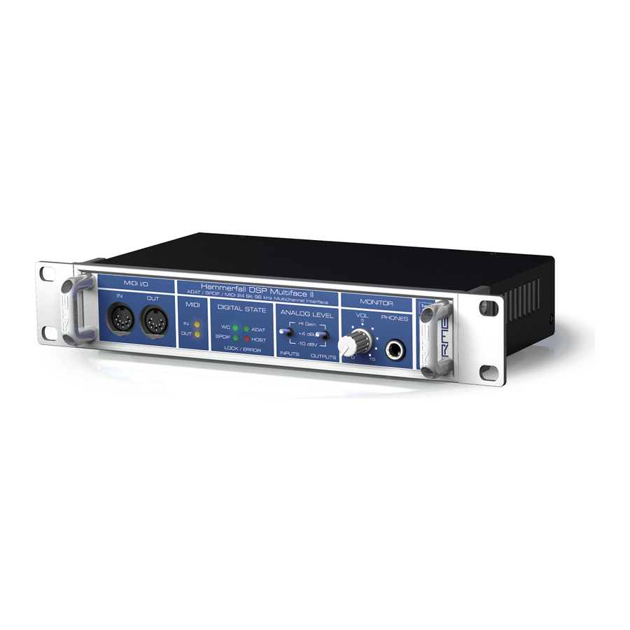
Page 8: Quick Start
The rear panel of the Multiface II has eight analog inputs and outputs, the Power socket (only necessary with CardBus/ExpressCard operation), Word Clock input and output, and both digital inputs and outputs ADAT and SPDIF. ADAT I/O (TOSLINK): Can also be used as optical SPDIF input and output, if set up accord- ingly in the Settings dialog. - Page 9 User's Guide Multiface II Driver Installation and Operation - Windows User's Guide HDSP System Multiface II © RME...
-
Page 10: Hardware Installation
6. Hardware Installation 6.1 PCI / PCIe Card Before installing the card, please make sure the computer is switched off and the power cable is disconnected from the mains supply. Inserting or removing the card while the com- puter is in operation can cause irreparable damage to both motherboard and card! 1. -
Page 11: Driver And Firmware
7. Driver and Firmware 7.1 Driver Installation After the interface has been installed correctly (see 6. Hardware Installation), and the computer has been switched on, Windows will recognize the new hardware component and start its ‘Hardware Wizard’. Insert the RME Driver CD into your CD-ROM drive, and follow further in- structions which appear on your computer screen. -
Page 12: Firmware Update
7.4 Firmware Update The Flash Update Tool updates HDSP PCI, PCIe, CardBus and ExpressCard to the latest ver- sion. It requires an already installed driver. Start the program hdsp_wdm_fut.exe (for all HDSP cards) or pcie_fut.exe (for all HDSPe cards). The Flash Update Tool displays the current revision of the HDSP interface, and whether it needs an update. -
Page 13: Configuring The Multiface
8. Configuring the Multiface II 8.1 Settings Dialog Configuration of the HDSP system Multiface is done via its own settings dialog. The panel 'Set- tings' can be opened: • by clicking on the hammer symbol in the Task Bar's notification area The mixer of the Hammerfall DSP System (TotalMix) can be opened: •... - Page 14 Clock Source The unit can be configured to use its own clock (Internal = Master), or one of the input signals (Word, SPDIF, ADAT). If the selected source isn't available (Input Status No Lock), the unit will change to the next available one (this behaviour is called AutoSync). If none is available then the internal clock is used.
-
Page 15: Clock Modes - Synchronization
8.2 Clock Modes - Synchronization In the digital world, all devices must be either Master (clock source) or Slave (clock receiver). Whenever several devices are linked within a system, there must always be a single master clock. A digital system can only have one master! If the HDSP’s clock mode is set to 'Master', all other devices must be set to ‘Slave’. -
Page 16: Operation And Usage
9. Operation and Usage 9.1 Playback The HDSP system can play back audio data in supported formats only (sample rate, bit resolu- tion). Otherwise an error message appears (for example at 22 kHz and 8 bit). In the audio application being used, HDSP must be selected as output device. This can often be found in the Options, Preferences or Settings menus under Playback Device, Audio Devices, Audio etc. -
Page 17: Dvd-Playback (Ac-3/Dts)
9.2 DVD-Playback (AC-3/DTS) AC-3 / DTS When using popular DVD software player like WinDVD and PowerDVD, their audio data stream can be sent to any AC-3/DTS capable receiver using the HDSP SPDIF output. For this to work, the WDM SPDIF device has to be selected in >Control Panel/ Sounds and Multimedia/ Audio< or >Control Panel/ Sound/Playback<. -
Page 18: Notes On Wdm
9.3 Notes on WDM The driver offers a WDM streaming device per stereo pair, like HDSP Multiface (1+2). WDM streaming is Microsoft's current driver and audio system, directly embedded into the operating system. WDM streaming is hardly usable for professional music purposes, as all data is proc- essed by the so called Kernel Mixer, causing a latency of at least 30 ms. -
Page 19: Channel Count Under Wdm
9.4 Channel Count under WDM The HDSP system’s ADAT optical ports allow to record sample rates of up to 96 kHz using a standard ADAT recorder. For this to work single-channel data is spread to two ADAT channels using the Sample Multiplexing technique. This reduces the number of available ADAT channels from 8 to 4. -
Page 20: Analog Recording
9.6 Analog Recording For recordings via the analog inputs the corresponding record device has to be chosen (HDSP Analog (x+x)). The input sensitivity of the analog inputs can be adjusted using the front panel switch ANALOG LEVEL INPUTS to meet the most often used studio levels, see chapter 22.1. It often makes sense to monitor the input signal or send it directly to the output. -
Page 21: Operation Under Asio
10. Operation under ASIO 10.1 General Start the ASIO software and select ASIO Hammerfall DSP as the audio I/O device. The Multiface supports ASIO Direct Monitoring (ADM). The Multiface’s MIDI I/O can be used with both MME MIDI and DirectMusic MIDI. 10.2 Channel Count under ASIO At a sample rate of 88.2 or 96 kHz, the ADAT optical input and output operate in S/MUX mode, so the number of available channels per port is reduced from 8 to 4. -
Page 22: Known Problems
10.3 Known Problems If a computer does not provide sufficient CPU-power and/or sufficient PCI-bus transfer rates, then drop outs, crackling and noise will appear. Raising the buffer size in the Settings dialog of the HDSP system helps in most cases. It is also recommended to deactivate all PlugIns to verify that these are not the reason for such effects. -
Page 23: Digicheck Windows
12. DIGICheck Windows The DIGICheck software is a unique utility developed for testing, measuring and analysing digi- tal audio streams. Although this Windows software is fairly self-explanatory, it still includes a comprehensive online help. DIGICheck 5.34 operates as multi-client ASIO host, therefore can be used in parallel to any software, be it WDM or ASIO, with both inputs and outputs (!). -
Page 24: Hotline - Troubleshooting
13. Hotline – Troubleshooting The newest information can always be found on our website www.rme-audio.com, section FAQ, Latest Additions. The dialog 'New hardware component found’ does not appear: • Check whether the CardBus card is completely inserted into the PCMCIA slot, or the PCI interface is correctly inserted in the PCI slot. -
Page 25: Driver Installation And Operation - Mac Os X
User's Guide Multiface II Driver Installation and Operation – Mac OS X User's Guide HDSP System Multiface II © RME... -
Page 26: Hardware Installation
14. Hardware Installation 14.1 PCIe Card Before installing the card, please make sure the computer is switched off and the power cable is disconnected from the mains supply. Inserting or removing the card while the com- puter is in operation can cause irreparable damage to both motherboard and card! 1. -
Page 27: Driver And Firmware
15. Driver and Firmware 15.1 Driver Installation First fit the card (see 14. Hardware Installation), then switch on the computer and install the drivers from the RME Driver CD. The driver file is located in the folder HDSPe Series. Installa- tion works automatically by a double-click on the file hdspe.pkg. -
Page 28: Configuring The Multiface
16. Configuring the Multiface II 16.1 Settings Dialog Configuring the Multiface II is done via its own settings dialog. The panel 'Settings' can be opened by clicking on the hammer icon in the dock. The mixer of the Hammerfall DSP System, TotalMix, can be opened by clicking on the mixer icon in the dock. - Page 29 I/O Box Disconnect interrupts the communication between I/O-box and PCI or CardBus card. In case the Multiface has been configured using the Settings dialog and TotalMix, Disconnect allows to use it Stand-Alone (without a connected computer), after a power supply has been attached. The status display below shows the current state of the I/O-boxt: Error: I/O-box not connected or missing power...
-
Page 30: Clock Modes - Synchronization
16.2 Clock Modes - Synchronisation In the digital world, all devices are either the ‘Master’ (clock source) or a ‘Slave’ synchronized to the master. Whenever several devices are linked within a system, there must always be a sin- gle master clock. The Hammerfall DSP’s intelligent clock control is very user-friendly, being able to switch between clock modes automatically. - Page 31 If several digital devices are to be used simultaneously in a system, they not only have to oper- ate with the same sample frequency but also be synchronous with each other. This is why digi- tal systems always need a single device defined as ‘master’, which sends the same clock signal to all the other (‘slave’) devices.
-
Page 32: Mac Os X Faq
17. Mac OS X FAQ 17.1 Round about Driver Installation The driver with the file suffix zip provided by RME is a compressed archive. Zip is directly sup- ported by OS X, a double click on the file is all one needs to do. The driver consists of a package file (pkg). -
Page 33: Channel Count Under Core Audio
17.5 Channel Count under Core Audio At a sample rate of 88.2 or 96 kHz, the ADAT optical input and output operates in S/MUX mode, so the number of available channels is reduced from 8 to 4. It is not possible to change the number of Core Audio devices without a reboot of the computer. Therefore whenever the Fireface changes into Double Speed (88.2/96 kHz) mode all devices stay present, but become partly inactive. -
Page 34: Digicheck Mac
19. DIGICheck Mac The DIGICheck software is a unique utility developed for testing, measuring and analysing digi- tal audio streams. Although this Windows software is fairly self-explanatory, it still includes a comprehensive online help. DIGICheck 0.64 operates in parallel to any software, showing all input data. -
Page 35: Disconnect Mode, Connections And Totalmix
User's Guide Multiface II Disconnect Mode, Connections and TotalMix User's Guide HDSP System Multiface II © RME... -
Page 36: Disconnect Mode
21. Disconnect Mode RME's exclusive Disconnect mode lets you adjust level, input selection and signal mix via your computer, and simply detach the Multiface afterwards. With this, a stand-alone operation of the Multiface gets possible. When the Multiface has been configured using Settings dialog and To- talMix, it won't loose those settings after detaching it from the computer if an external power supply is used, because the Multiface (as all HDSP I/O-boxes) does not contain memory, so all settings get lost upon power-off. -
Page 37: Line Outputs
22.2 Line Outputs The eight short circuit protected, low impedance line outputs are available as 1/4" TRS jacks on the back of the unit. The electronic output stage is built in a servo balanced design which han- dles unbalanced (mono jacks) and balanced (stereo jacks) correctly. To maintain an optimum level for devices connected to the analog outputs, the Multiface II in- ternally uses hi-quality electronic switches, which allow for a perfect adaptation of all rear out- puts to the three most often used studio levels. -
Page 38: Digital Connections
23. Digital Connections 23.1 ADAT The ADAT optical input of the HDSP system is fully compatible with all ADAT optical outputs. RME's unsurpassed Bitclock PLL prevents clicks and drop outs even in extreme varipitch op- eration, and guarantees a fast and low jitter lock to the digital input signal. A usual TOSLINK cable is sufficient for connection. -
Page 39: Word Clock
The Multiface’s new output header is optimized for largest compatibility with other digital de- vices: • 32 kHz, 44.1 kHz, 48 kHz, 88.2 kHz, 96 kHz depending on the current sample rate • Audio use, Non-Audio • No Copyright, Copy Permitted •... -
Page 40: Word Clock
24. Word Clock 24.1 Technical Description and Usage In the analog domain one can connect any device to another device, a synchronization is not necessary. Digital audio is different. It uses a clock, the sample frequency. The signal can only be processed and transmitted when all participating devices share the same clock. -
Page 41: General Operation
The word clock input of the Hammerfall DSP is a high-impedance type ensuring maximum flexi- bility, and is therefore not terminated. If normal termination is necessary (e.g. because Ham- merfall DSP is the last device in the chain), simply connect a T-adapter to its BNC input jack, connect the cable supplying the word clock signal to one arm of the T-adapter and terminate the other with a 75 Ohm resistor (as a short BNC plug). - Page 42 User's Guide HDSP System Multiface II © RME...
- Page 43 User's Guide Multiface II TotalMix User's Guide HDSP System Multiface II © RME...
-
Page 44: Totalmix: Routing And Monitoring
25. TotalMix: Routing and Monitoring 25.1 Overview The Multiface includes a powerful digital real-time mixer, the Hammerfall DSP mixer, based on RME’s unique, sample-rate independent TotalMix technology. It allows for practically unlimited mixing and routing operations, with all inputs and playback channels simultaneously, to any hardware outputs. - Page 45 User's Guide HDSP System Multiface II © RME...
-
Page 46: The User Interface
25.2 The User Interface The visual design of the TotalMix mixer is a result of its capability to route hardware inputs and software playback channels to any hardware output. The Multiface provides 18 input channels, 18 software playback channels, and 20 hardware output channels: 36 channels don't fit on the screen side by side, neither does such an arrangement provide a useful overview. -
Page 47: Elements Of A Channel
25.3 The Channels A single channel consists of various elements: Input channels and playback channels each have a mute and solo button. Below there is the panpot, realized as indicator bar (L/R) in order to save space. In the field below, the present level is displayed in RMS or Peak, being updated about every half a second. - Page 48 You see, it is very easy to set up a specific submix for whatever output: select output channel, set up fader and pans of inputs and playbacks – ready! For advanced users sometimes it makes sense to work without Submix View. Example: you want to see and set up some channels of different submixes simultaneously, without the need to change between them all the time.
-
Page 49: Submix View
You will certainly have noticed that the signal at the outputs 7/8 did not change while you were routing channel 4 to other outputs and setting different gain values for those. With all analog and most digital mixing desks, the fader setting would affect the level for every routed bus - not so for TotalMix. -
Page 50: Quick Access Panel
25.7 The Quick Access Panel This section includes additional options, further improving the handling of TotalMix. The Master buttons for Mute and Solo have already been described, they allow for group-based working with these functions. In the View section the single mixer rows can be made visible or invisible. If the inputs are not needed for a pristine playback mix, the whole upper row falls out of the picture after a click on the Input button. - Page 51 Mouse: The original factory presets can be reloaded by holding down the Ctrl-key and clicking on any preset button. Alternatively the files described above can be renamed, moved to a dif- ferent directory, or being deleted. Keyboard: Using Ctrl and any number between 1 and 8 (not on the numeric keypad!) will load the corresponding factory default preset.
-
Page 52: Monitor Panel
25.9 The Monitor Panel The Monitor panel provides several options usually found on analog mixing desks. It offers quick access to monitoring functions which are needed all the time in typical studio work. Monitor Main Use the drop down menu to select the hardware outputs where your main monitors are con- nected to. -
Page 53: Editing The Names
MIDI Controller MIDI In: Input where TotalMix receives MIDI Remote data. MIDI Out: Output where TotalMix sends MIDI Remote data. Mackie Control Options Enable Protocol Support: When disabled TM FX will only react on the Control Change com- mands of chapter 28.5. Enable full LCD support: Activates full Mackie Control LCD support with eight channel names and eight volume/pan values. -
Page 54: Hotkeys
25.12 Hotkeys In many situations TotalMix can be controlled quickly and comfortably by the keyboard, making the mixer setup considerably easier and faster. The Shift-key for the fine mode for faders and panpots has already been mentioned. The Ctrl-key can do far more than changing the routing pairwise: •... -
Page 55: Menu Options
25.13 Menu Options Always on Top: When active (checked) the TotalMix window will always be on top of the Win- dows desktop. Note: This function may result in problems with windows containing help text, as the TotalMix window will even be on top of those windows, so the help text isn't readable. Deactivate Screensaver: When active (checked) any activated Windows screensaver will be disabled temporarily. -
Page 56: Level Meter
25.15 Level Meter The Multiface II calculates all the display values Peak, Over and RMS in hardware, in order to be capable of using them independent of the software in use, and to significantly reduce the CPU load. Tip: This feature, the Hardware Level Meter, is used by DIGICheck (see chapter 12/19) to display Peak/RMS level meters of all channels, nearly without any CPU load. -
Page 57: Totalmix: The Matrix
26. TotalMix: The Matrix 26.1 Overview The mixer window of TotalMix looks and operates similar to mixing desks, as it is based on a conventional stereo design. The matrix display presents a different method of assigning and routing channels, based on a single channel or monaural design. The matrix view of the HDSP has the looks and works like a conventional patchbay, adding functionality way beyond compa- rable hardware and software solutions. -
Page 58: Advantages Of The Matrix
26.4 Advantages of the Matrix The Matrix not always replaces the mixer view, but it significantly enhances the routing capabili- ties and - more important - is a brilliant way to get a fast overview of all active routings. It shows you in a glance what's going on. -
Page 59: Selection And Group Based Operation
27.2 Selection and Group-based Operation Click on the white name label of channel 1 and 2 in TotalMix. Be sure to have channel 3's fader set to a different position and click on its label too. All three labels have changed to the colour orange, which means they are selected. -
Page 60: Recording A Subgroup (Loopback)
27.5 Recording a Subgroup (Loopback) TotalMix supports a routing of the subgroup outputs (=hardware outputs, bottom row) to the recording software. Instead of the signal at the hardware input, the signal at the hardware out- put is sent to the record software. This way, complete submixes can be recorded without an external loopback cable. -
Page 61: Using External Effects Devices
Recording a Software's playback In real world application, recording a software's output with another software will show the fol- lowing problem: The record software tries to open the same playback channel as the playback software (already active), or the playback one has already opened the input channel which should be used by the record software. -
Page 62: Ms Processing
As explained in chapter 27.5, the hardware input of channel 10 now no longer feeds the record software, but is still connected to TotalMix (and thus to the Compressor). The record software receives the signal of submix channel 10 instead – the Compressor's return path. 27.8 MS Processing The mid/side principle is a special positioning technique for microphones, which results in a mid signal on one channel and a side signal on the other channel. -
Page 63: Totalmix Midi Remote Control
28. TotalMix MIDI Remote Control 28.1 Overview TotalMix can be remote controlled via MIDI. It is compatible to the widely spread Mackie Control protocol, so TotalMix can be controlled with all hardware controllers supporting this standard. Examples are the Mackie Control, Tascam US-2400 or Behringer BCF 2000. Additionally, the stereo output faders (lowest row) which are set up as Monitor Main outputs in the Monitor panel can also be controlled by the standard Control Change Volume via MIDI channel 1. -
Page 64: Setup
28.3 Setup • Open the Preferences dialog (menu Options or F3). Select the MIDI Input and MIDI Output port where your controller is connected to. • When no feedback is needed (when using only standard MIDI commands instead of Mackie Control protocol) select NONE as MIDI Output. -
Page 65: Simple Midi Control
28.5 Simple MIDI Control The stereo output faders (lowest row) which are set up as Monitor Main outputs in the Monitor panel can also be controlled by the standard Control Change Volume via MIDI channel 1. With this, the main volume of the Multiface is controllable from nearly any MIDI equipped hard- ware device. -
Page 66: Loopback Detection
Examples for sending MIDI strings*: - Set input 1 to 0 dB: B0 66 40 - Set input 17 to maximum attenuation: B1 66 0 - Set playback 1 to maximum: B4 66 7F - Set Output 16 to 0 dB: B8 75 40 *Note: Sending MIDI strings requires the use of programmer's logic for the MIDI channel, start- ing with 0 for channel 1 and ending with 15 for channel 16. -
Page 67: Technical Reference
User's Guide Multiface II Technical Reference User's Guide HDSP System Multiface II © RME... -
Page 68: Technical Specifications
29. Technical Specifications 29.1 Analog • Resolution: 24 bit • Signal to Noise ratio (SNR): 107.5 dB RMS unweighted, 111.5 dBA • THD: < -100 dB, < 0.001 % • THD+N: < -98 dB, < 0.0012 % • Channel separation: > 100 dB •... -
Page 69: Digital
29.3 Digital Inputs SPDIF - AES/EBU • 1 x RCA, transformer-balanced, galvanically isolated, according to AES3-1992 • High-sensitivity input stage (< 0.3 Vpp) • SPDIF compatible (IEC 60958) • Accepts Consumer and Professional format, copy protection will be ignored • Lock range: 28 kHz – 103 kHz •... -
Page 70: Technical Background
29.6 General • Power supply: external switching power supply, 100 - 240 V AC, 15 Watt • Current at 12 Volt operating voltage, unloaded: 720 mA (8.6 Watt) • Current at 12 Volt operating voltage, loaded: 1 A (12 Watt) •... -
Page 71: General
30.2 Latency and Monitoring The term Zero Latency Monitoring has been introduced by RME in 1998 for the DIGI96 series of audio cards. It stands for the ability to pass-through the computer's input signal at the inter- face directly to the output. Since then, the idea behind has become one of the most important features of modern hard disk recording. -
Page 72: Ds - Double Speed
Note: Cubase and Nuendo display the latency values signalled from the driver separately for record and playback. While with our former cards these values equalled exactly the buffer size (for example 3 ms at 128 samples), the Multiface displays an additional millisecond – the time needed for the AD/DA-conversion. -
Page 73: Aes/Ebu - Spdif
30.4 AES/EBU - SPDIF The most important electrical properties of 'AES' and 'SPDIF' can be seen in the table below. AES/EBU is the professional balanced connection using XLR plugs. The standard is being set by the Audio Engineering Society based on the AES3-1992. For the 'home user', SONY and Philips have omitted the balanced connection and use either Phono plugs or optical cables (TOSLINK). -
Page 74: Diagrams 31.1 Block Diagram Multiface Ii
31. Diagrams 31.1 Block Diagram Multiface II User's Guide HDSP System Multiface II © RME... -
Page 75: Connector Pinouts
31.2 Connector Pinouts TRS jacks of analog input / output The stereo ¼" TRS jacks of the analog inputs and outputs are wired according to international standards: Tip = + (hot) Ring = – (cold) Sleeve = GND The servo balanced input and output circuitry allows to use monaural TS jacks (unbalanced) with no loss in level. - Page 76 User's Guide HDSP System Multiface II © RME...
-
Page 77: Miscellaneous
User's Guide Multiface II Miscellaneous User's Guide HDSP System Multiface II © RME... -
Page 78: Accessories
32. Accessories RME offers several optional accessories. Additionally parts of the HDSP system are available separately. Part Number Description 36000 19“, 1UH Universal rack holder This 19" rack holder has holes for Digiface and Multiface. Two units can be installed side by side in any combination. -
Page 79: Warranty
33. Warranty Each individual Hammerfall DSP undergoes comprehensive quality control and a complete test at IMM before shipping. The usage of high grade components should guarantee a long and trouble-free operation of the unit. If you suspect that your product is faulty, please contact your local retailer. Audio AG grants a limited manufacturer warranty of 6 months from the day of invoice showing the date of sale. -
Page 80: Declaration Of Conformity
35. Declaration of Conformity CE / FCC Compliance This device has been tested and found to comply with the limits of the European Council Direc- tive on the approximation of the laws of the member states relating to electromagnetic compati- bility according to RL2004/108/EG, and European Low Voltage Directive RL2006/95/EG.
Need help?
Do you have a question about the DSP System Multiface and is the answer not in the manual?
Questions and answers