Table of Contents
Advertisement
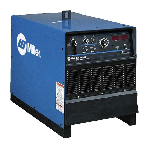
Gold Star® 402, 602, 852 (50/60 HZ -
CC/DC Welding Power Sources For SMAW, GTAW Welding, And CAC-A Cutting And Gouging
Rated
Amp
Model
Model
Welding
Welding
Range
Range
Output
DC
300 A @
300
32 Volts
15 − 395
Amp
DC, 60%
Duty Cycle
450 A @
450
38 Volts
20 − 590
Amp
DC, 60%
Duty Cycle
650 A @
650
44 Volts
50 − 850
Amp
DC, 60%
Duty Cycle
*While idling
( ) Indicates specification differences for CE models
cover_om 4/95 − ST-800 168-B
OWNER'S
MANUAL
Gold Star® 302, 452, 652 (60 HZ)
Maximum
Open-
IP
Circuit
Circuit
Rating
Rating
Voltage
DC
72
21M
(70)
72
21M
(70)
72
21M
(70)
©
1996 MILLER Electric Mfg. Co.
January 1996
Effective With Serial No. KG054113
Amperes Input at Rated Load Output, 50 or 60 Hz,
Three-Phase
200 V 230 V 380 V 400 V 440 V 460 V 575 V
61
35
33
__
3.6*
1.1*
1.1*
102
89
54
51
3.5*
3.1*
1.5*
1.4*
124
75
71
−−
5.2*
1.7*
1.6*
Form: OM-222D
)
KVA
31
31
25
24.5
1.0*
3.1*
1.5*
1.3*
47
45
36
35.5
1.2*
1.5*
1.2*
1.2*
65
62
50
49.4
1.5*
2.6*
2.1*
2.1*
PRINTED IN USA
KW
13.8
0.67*
23.3
0.51*
36
0.58*
Advertisement
Table of Contents
Troubleshooting

Related Manuals for Miller GOLDSTAR 302


Summary of Contents for Miller GOLDSTAR 302
- Page 1 50 − 850 −− (70) 5.2* 1.7* 1.6* 1.5* 2.6* 2.1* 2.1* 0.58* DC, 60% Duty Cycle *While idling ( ) Indicates specification differences for CE models © cover_om 4/95 − ST-800 168-B 1996 MILLER Electric Mfg. Co. PRINTED IN USA...
-
Page 2: Who Do I Contact
(Equipment with a serial number preface of “KD” or newer) This limited warranty supersedes all previous MILLER warranties and is exclusive with no other guarantees or warranties expressed or implied. LIMITED WARRANTY − Subject to the terms and conditions below, MILLER Elec- 6 Months —... - Page 3 Declaration of Conformity For European Community (CE) Products NOTE This information is provided for units with CE certification (see rating label on unit.) Miller Electric Mfg. Co. Manufacturer’s Name: 1635 W. Spencer Street Manufacturer’s Address: Appleton, WI 54914 USA Goldstar® 402, 602, And 852...
-
Page 4: Section 1 − Safety Precautions For Arc Welding
SECTION 1 − SAFETY PRECAUTIONS FOR ARC WELDING OM-222D 1/96 safety_som1 4/95 1-1. Symbol Usage Y Marks a special safety message. Means Warning! Watch Out! There are possible hazards with this procedure! The possible hazards are shown in the adjoining symbols. Means NOTE;... - Page 5 CYLINDERS can explode if damaged. 4. Never drape a welding torch over a gas cylinder. 5. Never allow a welding electrode to touch any cylinder. Shielding gas cylinders contain gas under high 6. Never weld on a pressurized cylinder − explosion will result. pressure.
-
Page 6: Principal Safety Standards
OVERUSE can cause OVERHEATED SIGNIFICANT DC VOLTAGE exists after EQUIPMENT. removal of input power on inverters. 1. Allow cooling period. 1. Turn Off inverter, disconnect input power, and 2. Reduce current or reduce duty cycle before discharge input capacitors according starting to weld again. -
Page 7: Section 2 − Definitions
SECTION 2 − DEFINITIONS 2-1. Warning Label Definitions Warning! Watch Out! There are possible hazards as shown by the symbols. Electric shock from welding electrode or wiring can kill. 1.1 Wear dry insulating gloves. Do not touch electrode with bare hand. Do not wear wet or damaged gloves. - Page 8 Warning! Watch Out! There are possible hazards as shown by the symbols. Electric shock from wiring can kill. Disconnect input plug or power before working on machine. Read the Owner’s Manual before working on this machine. Consult rating label for input power requirements, and check power available at the job site −...
-
Page 9: Manufacturer's Rating Labels For Ce Products
2-2. Manufacturer’s Rating Labels For CE Products Match label to one on unit. See Section 3-1. S-174 342 / S-174 340 / S-174 341 OM-222 Page 6... -
Page 10: Symbols And Definitions
2-3. Symbols And Definitions NOTE Some symbols are found only on CE products. Amperage Control/ Gas Tungsten Arc Shielded Metal Arc Amperes Panel Welding (GTAW) Welding (SMAW) Do Not Switch Temperature Arc Force (DIG) Percent While Welding Output Circuit Breaker Remote Volts Protective Earth... -
Page 11: Selecting A Location
SECTION 3 − INSTALLATION 3-1. Selecting A Location Lifting Eye Lifting Forks Use lifting eye or lifting forks to move unit. Movement If using lifting forks, extend forks beyond opposite side of unit. Rating Label (Non CE Models Only) Use rating label to determine input power needs. -
Page 12: 115 Vac Receptacle And Circuit Breakers
3-3. Tipping Y Be careful when placing or moving unit over uneven surfaces. 3-4. 115 VAC Receptacle And Circuit Breakers Y Turn power before connecting to receptacle. 115 V 15 A AC Receptacle Power is shared between RC9 and Remote 14 receptacle RC8 or terminal strip 1T (see Section 3-7). -
Page 13: Remote Output Control
3-5. Weld Output Terminals And Selecting Cable Sizes Y ARC WELDING can cause Electromagnetic Interference. To reduce possible interference, keep weld cables as short as possible, close together, and down low, such as on the floor. Locate welding operation 100 meters from any sensitive electronic equipment. Be sure this welding machine is installed and grounded according to this manual. -
Page 14: Connecting Remote Control
3-7. Connecting Remote Control Remote 14 Receptacle RC8 Connect remote control to RC8. If plug does not fit, wire cord to termi- nal strip 1T. Y Turn power before opening terminal strip cover. Terminal Strip 1T Remote Control Cord Strain Relief (Customer Supplied) Secure cord in strain relief. -
Page 15: Electrical Service Guide
3-8. Electrical Service Guide 60 Hertz Models 300 Amp Model 450 Amp Model 650 Amp Model Input Voltage Input Amperes At Rated Output Max Recommended Standard Fuse Or Circuit Breaker Rating In Amperes Min Input Conductor Size In AWG/Kcmil Max Recommended Input Conductor Length In Feet (Meters) (35) (94) -
Page 16: Placing Jumper Links And Connecting Input Power
3-9. Placing Jumper Links And Connecting Input Power 200 VOLTS 230 VOLTS 460 VOLTS Ref. S-174 976-A 230 VOLTS 460 VOLTS 575 VOLTS Ref. S-174 973-A 220 VOLTS 380 VOLTS 400 VOLTS 440 VOLTS (FACTORY OPTION) Ref. S-174 975-A Do not overtighten GND/PE jumper link nuts. -
Page 17: Section 4 − Operation
SECTION 4 − OPERATION 4-1. Controls Ref. ST-800 101-C Polarity Selector Switch (Optional On electrode. Remote Amperage Control Switch 50 Hz Models) For front panel control, place switch in Panel Set control at 0 for normal welding To change polarity on models not equipped position. -
Page 18: Duty Cycle And Overheating
4-2. Duty Cycle And Overheating Duty Cycle is percentage of 10 min- utes that unit can weld at rated load without overheating. If unit overheats, thermostat(s) opens, output stops, and cooling fan runs. Wait fifteen minutes for unit to cool. Reduce amperage or duty cycle before welding. -
Page 19: Troubleshooting
5-2. Fuse F1 Y Turn Off power before open- ing rear access door. Fuse F1 (See Parts List For Rating) Fuse F1 protects control transform- er from overload. If F1 opens, weld output and fan motor stops. Re- place F1. Tools Needed: 3/8 in Ref. -
Page 20: Section 6 − Electrical Diagram
SECTION 6 − ELECTRICAL DIAGRAM For Primary Circuit Diagram Portion, refer to the Circuit Diagram located inside the wrapper of the welding power source. SC-175 486 Figure 6-1. Circuit Diagram OM-222 Page 17... -
Page 21: Section 7 − Parts List
SECTION 7 − PARTS LIST ST-800 875-A Figure 7-1. Main Assembly (452 Model Illustrated) OM-222 Page 18... - Page 22 Quantity Model Item Dia. Part Mkgs. Description 302 452 652 Figure 7-1. Main Assembly ....+168 793 PANEL, side LH ........
- Page 23 Quantity Model Item Dia. Part Mkgs. Description 302 452 652 Figure 7-1. Main Assembly (Continued) ... . 172 408 TRANSFORMER, pwr main 380/400/440 (consisting of) ...
- Page 24 Quantity Model Item Dia. Part Mkgs. Description 302 452 652 Figure 7-2. Panel, Front w/Components (Fig 7-1 Item 32) ..♦169 331 SWITCH, mode polarity (single deck) ..... .
- Page 25 Quantity Model Item Dia. Part Mkgs. Description 302 452 652 Figure 7-2. Panel, Front w/Components (Fig 7-1 Item 32) (Continued) ..039 047 TERMINAL, pwr output red (consisting of) ....
- Page 26 Item Dia. Part Mkgs. Description Quantity 175 070 Figure 7-3. Rectifier, Si Diode (302 Model) (Fig 7-1 Item 33) ..C7-12 ..048 420 CAPACITOR, cer disc .01uf 1000VDC ......
- Page 27 Item Dia. Part Mkgs. Description Quantity Figure 7-5. Panel, Rear w/Components (Fig 7-1 Item 19) ....173 283 CHAMBER, plenum 14 in ........
- Page 28 Notes...
-
Page 29: Options And Accessories
PROTECTION PACKAGE design conveniently mounts to Fastens to TIG torch using two (#043 049 Factory) Miller cylinder rack in place of one Velcro strips. Allows complete Internal machine components are cylinder. For more information, see current and contactor control at... - Page 30 OPTIONS AND ACCESSORIES GMAW/FCAW WELDING RHC-14 HAND CONTROL EXTENSION CABLES FOR 14-PIN (#129 340) S-32S PORTABLE WIRE FEEDER Miniature hand control for remote PLUGS TO 14-PIN SOCKETS (#088 816) current and contactor control. For .035 - 5/64 in. (0.6 - 2.0 mm) Dimensions: 4 in.
Need help?
Do you have a question about the GOLDSTAR 302 and is the answer not in the manual?
Questions and answers