Table of Contents
Advertisement
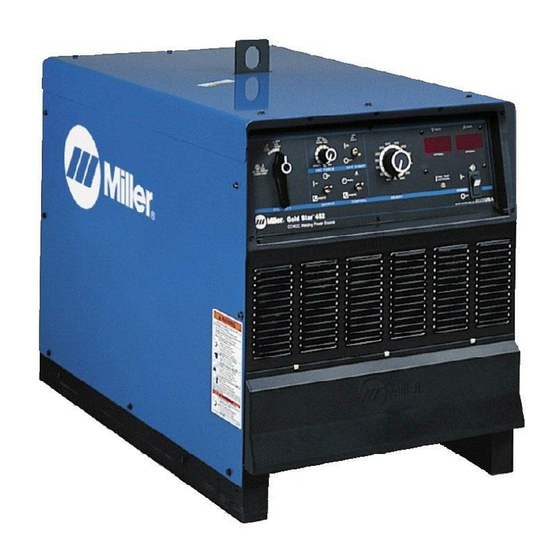
Gold Star® 302, 452, And 652 (60 HZ)
Gold Star® 402, 602, And 852 (50 HZ)
CC/DC Welding Power Sources For SMAW, GTAW Welding, And CAC-A Cutting And Gouging
Rated
Amperage
Model
Model
Welding
Welding
Range DC
Range DC
Output
300 A @ 32
Volts DC,
300 Amp
60% Duty
Cycle
450 A @ 38
Volts DC,
450 Amp
60% Duty
Cycle
650 A @ 44
Volts DC,
650 Amp
60% Duty
Cycle
*While idling
cover_om 4/95 − ST-800 168-B
OWNER'S
MANUAL
Maximum
Open-
Circuit
Circuit
200 V 230 V 380 V 400 V 440 V 460 V 575 V
Voltage DC
15 − 395
72
20 − 590
72
50 − 850
72
©
1995 MILLER Electric Mfg. Co.
August 1995
Effective With Serial No. KF840452
Amperes Input at Rated Load Output, 50 or 60 Hz,
Three-Phase
61
35
33
__
(3.6)*
(2.3)*
(2.1)*
102
89
52
49
(3.5)*
(3.1)*
(2.5)*
(2.4)*
124
76
72
−−
(5.2)*
(2.4)*
(2.2)*
Form: OM-222A
KVA
30
31
25
24.5
(2.0)*
(3.1)*
(1.5)*
(1.3)*
46
45
36
35.5
(2.2)*
(1.5)*
(1.2)*
(1.2)*
65
62
50
49.4
(2.0)*
(2.6)*
(2.1)*
(2.1)*
PRINTED IN USA
KW
13.8
(0.67)*
23.3
(0.51)*
36
(0.58)*
Advertisement
Table of Contents
Troubleshooting

Related Manuals for Miller GOLDSTAR 302


Summary of Contents for Miller GOLDSTAR 302
- Page 1 650 A @ 44 Volts DC, 49.4 650 Amp 50 − 850 −− 60% Duty (5.2)* (2.4)* (2.2)* (2.0)* (2.6)* (2.1)* (2.1)* (0.58)* Cycle *While idling © cover_om 4/95 − ST-800 168-B 1995 MILLER Electric Mfg. Co. PRINTED IN USA...
-
Page 2: Limited Warranty
(Equipment with a serial number preface of “KD” or newer) This limited warranty supersedes all previous MILLER warranties and is exclusive with no other guarantees or warranties expressed or implied. LIMITED WARRANTY − Subject to the terms and conditions below, MILLER Elec- 6 Months —... -
Page 3: Table Of Contents
TABLE OF CONTENTS SECTION 1 − SAFETY PRECAUTIONS FOR ARC WELDING ....... . 1-1. -
Page 5: Section 1 − Safety Precautions For Arc Welding
SECTION 1 − SAFETY PRECAUTIONS FOR ARC WELDING safety_som1 4/95 1-1. Symbol Usage Y Marks a special safety message. Means Warning! Watch Out! There are possible hazards with this procedure! The possible hazards are shown in the adjoining symbols. Means NOTE; not safety related. This group of symbols means Warning! Watch Out! possible ELECTRIC SHOCK, MOVING PARTS, and HOT PARTS hazards. -
Page 6: Additional Installation, Operation, And Maintenance Hazards
CYLINDERS can explode if damaged. 4. Never drape a welding torch over a gas cylinder. 5. Never allow a welding electrode to touch any cylinder. Shielding gas cylinders contain gas under high 6. Never weld on a pressurized cylinder − explosion will result. pressure. -
Page 7: Principal Safety Standards
OVERUSE can cause OVERHEATED SIGNIFICANT DC VOLTAGE exists after EQUIPMENT. removal of input power on inverters. 1. Allow cooling period. 1. Turn Off inverter, disconnect input power, and 2. Reduce current or reduce duty cycle before discharge input capacitors according starting to weld again. -
Page 8: Section 2 − Installation
SECTION 2 − INSTALLATION NOTE See User’s Guide on unit for process connection information. 2-1. Selecting A Location Lifting Eye Lifting Forks Use lifting eye or lifting forks to move unit. If using lifting forks, extend forks beyond opposite side of unit. Movement Rating Label (Under Access Door) -
Page 9: Weld Output Terminals And Selecting Cable Sizes
2-3. Weld Output Terminals And Selecting Cable Sizes Total Cable (Copper) Length In Weld Circuit Not Exceeding 150 ft 200 ft 250 ft 300 ft 350 ft 400 ft 100 ft (30 m) Or Less (45 m) (60 m) (70 m) (90 m) (105 m) (120 m) -
Page 10: Connecting Remote Control
2-5. Connecting Remote Control Remote 14 Receptacle RC8 Connect optional remote control to RC8. If remote control plug does not fit RC8, wire cord to terminal strip 1T. Terminal connections are not direct replacements sockets in Remote 14 recep- tacle (see Section 2-4). Y Turn Off power before open- ing terminal strip cover. -
Page 11: 115 Volts Ac Duplex Receptacle
2-6. 115 Volts AC Duplex Receptacle Y Turn Off power before con- necting to receptacle. Weld output terminals are ener- gized when Output switch is On and Power is On. 115 V 15 A AC Receptacle Power is shared between RC9 and Remote 14 receptacle RC8 or terminal strip 1T (see Section 2-5). -
Page 12: Placing Jumper Links And Connecting Input Power
2-8. Placing Jumper Links And Connecting Input Power 200 VOLTS 230 VOLTS 460 VOLTS S-163 963 230 VOLTS 460 VOLTS 575 VOLTS S-168 940 220 VOLTS 380 VOLTS 400 VOLTS 440 VOLTS (FACTORY OPTION) S-171 177-A GND/PE Earth Ground L1 (U) L2 (V) L3 (W) IMPORTANT... -
Page 13: Section 3 − Operation
SECTION 3 − OPERATION 3-1. Controls Ref. ST-165 597-B Polarity Selector Switch (Optional On Control increases SMAW short-circuit am- Amperage Adjustment Control 50 Hz Models) perage which allows the operator to use a Digital Meters (Optional) very short arc length without sticking the To change polarity on models not equipped Power Switch With Indicator Light electrode. -
Page 14: Duty Cycle And Overheating
3-2. Duty Cycle And Overheating Duty Cycle is percentage of 10 min- utes that unit can weld at rated load without overheating. If unit overheats, thermostat(s) opens, output stops, and cooling fan runs. Wait fifteen minutes for unit to cool. Reduce amperage or duty cycle before welding. -
Page 15: Fuse F1
4-2. Fuse F1 Y Turn Off power before open- ing rear panel access door. Fuse F1 (See Parts List For Rating) Fuse F1 protects control transform- er from overload. If F1 opens, weld output and fan motor stops. Re- place F1. Tools Needed: 3/8 in Ref. -
Page 16: Section 5 − Electrical Diagram
SECTION 5 − ELECTRICAL DIAGRAM SC-175 486 Figure 5-1. Circuit Diagram For Welding Power Source OM-222 Page 12... - Page 17 NOTES OM-222 Page 13...
-
Page 18: Section 6 − Parts List
SECTION 6 − PARTS LIST ST-800 875-A Figure 6-1. Main Assembly (452 Model Illustrated) OM-222 Page 14... - Page 19 Quantity Model Item Dia. Part Mkgs. Description 302 452 652 Figure 6-1. Main Assembly ....+168 793 PANEL, side LH ........
- Page 20 Quantity Model Item Dia. Part Mkgs. Description 302 452 652 Figure 6-1. Main Assembly (Continued) ... . 172 408 TRANSFORMER, pwr main 380/400/440 (consisting of) ...
- Page 21 Quantity Model Item Dia. Part Mkgs. Description 302 452 652 Figure 6-2. Panel, Front w/Components (Fig 6-1 Item 32) ♦169 331 ..SWITCH, mode polarity (single deck) ..... ♦169 332 .
- Page 22 Quantity Model Item Dia. Part Mkgs. Description 302 452 652 Figure 6-2. Panel, Front w/Components (Fig 6-1 Item 32) (Continued) ....601 880 ..NUT, .500-13 x .31 high stl .
- Page 23 Item Dia. Part Mkgs. Description Quantity 168 897 Figure 6-3. Rectifier, Si Diode (302 Model) (Fig 6-1 Item 33) ..C7-12 ..031 688 CAPACITOR, cer disc .01uf 1000VDC ......
- Page 24 Item Dia. Part Mkgs. Description Quantity Figure 6-5. Panel, Rear w/Components (Fig 6-1 Item 19) ....124 275 CHAMBER, plenum 14 in ........
- Page 25 Notes...
- Page 26 Notes...
-
Page 27: Options And Accessories
PROTECTION PACKAGE design conveniently mounts to Fastens to TIG torch using two (#043 049 Factory) Miller cylinder rack in place of one Velcro strips. Allows complete Internal machine components are cylinder. For more information, see current and contactor control at... - Page 28 OPTIONS AND ACCESSORIES GMAW/FCAW WELDING RHC-14 HAND CONTROL EXTENSION CABLES FOR 14-PIN (#129 340) S-32S PORTABLE WIRE FEEDER Miniature hand control for remote PLUGS TO 14-PIN SOCKETS (#088 816) current and contactor control. For .035 - 5/64 in. (0.6 - 2.0 mm) Dimensions: 4 in.
Need help?
Do you have a question about the GOLDSTAR 302 and is the answer not in the manual?
Questions and answers