Advertisement
Service Manual
2
3
1
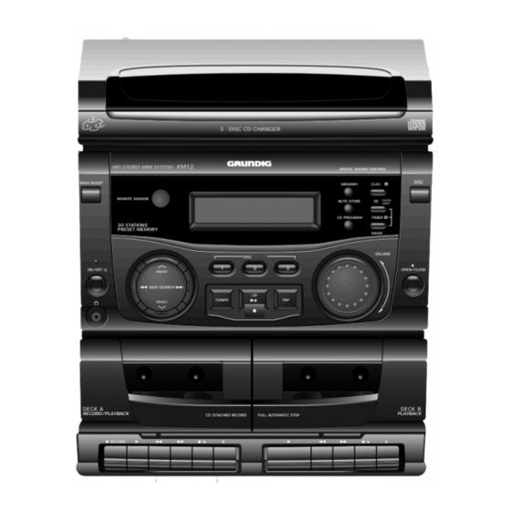
HIFI STEREO MINI SYSTEM -
BASS BOOST
REMOTE SENSOR
30 STATIONS
PRESET MEMORY
ON/OFF
S SKIP/SEARCH T
DECK A
RECORD/PLAYBACK
0 RECORD
B
Zusätzlich erforderliche
Unterlagen für den Komplettservice
Additionally required
Service Manuals for the Complete Service
Service
Service
Manual
Manual
Sicherheit
KM 12
Safety
Sach-Nr./Part No.
Sach-Nr./Part No.
72010-754.30
72010-800.00
3 - DISC CD CHANGER
KM12
DISC
C
1
2
3
PRESET
CD
a B;
TUNER
TAP
PRESET
D
9
CD SYNCHRO RECORD
FULL AUTOMATIC STOP
Q
R
9//
;
B
DIGITAL SOUND CONTROL
DSC
CLOC
MEMORY
CLOCK
AUTO STORE
SE
LIGHT
CD PROGRAM
TIMER
MODE
VOLUME
a /
OPEN/CLOSE
DECK B
PLAYBACK
Q
R
9//
;
HiFi
KM 12
Btx * 32700 #
Sachnummer
Part Number 72010-754.30
Änderungen vorbehalten
Subject to alteration
Printed in Germany
VK232 0697
Advertisement

Related Manuals for Grundig KM 12


Summary of Contents for Grundig KM 12
- Page 1 Service Manual HiFi KM 12 3 - DISC CD CHANGER KM12 HIFI STEREO MINI SYSTEM - DIGITAL SOUND CONTROL BASS BOOST CLOC MEMORY REMOTE SENSOR CLOCK AUTO STORE LIGHT CD PROGRAM TIMER 30 STATIONS PRESET MEMORY MODE VOLUME DISC OPEN/CLOSE...
-
Page 2: Table Of Contents
Cassette torque meter 456 Part No. 35079-014.00 Test-CD Sach-Nr. 72008-376.00 Test CD Part No. 72008-376.00 Beachten Sie bitte das GRUNDIG Meßtechnik-Programm, das Sie Please note the Grundig Catalog “Test and Measuring Equipment” unter folgender Adresse erhalten: obtainable from: GRUNDIG Instruments GRUNDIG Instruments Test- und Meßsysteme GmbH... -
Page 3: Technische Daten
KM 12 Allgemeiner Teil / General Section Technische Daten Technical Data Spannungsversorgung Power Supply Netzbetrieb ..............230V, 50/60Hz Mains operation ............230V, 50/60Hz Verstärkerteil Amplifier Section Ausgangsleistung DIN 45324, 10% THD Output power DIN 45324, 10% THD Musikleistung ............... 2 x 20W Music power ................. -
Page 4: Ausbauhinweise
Allgemeiner Teil / General Section KM 12 Ausbauhinweise Disassembly Instructions Die Teilebezeichnungen (wie z.B. M7A ) im Text und bei den Abbildun- The designations of parts (e.g. M7A ) in the text and figures are gen sind mit den Positionsnummern in den Ersatzteillisten und identical with the position numbers in the spare parts lists and exploded Explosionszeichnugen übereinstimmend. - Page 5 KM 12 Allgemeiner Teil / General Section Fig. 6 Fig. 5 3. CD-Teil ausbauen 3. Removing the CD Unit - Gehäuseoberteil M35 mit CD-Teil ausbauen (Punkt 1). - Remove cabinet top M35 with the CD unit (point 1). - 4 Schrauben M30 herausschrauben (Fig.
- Page 6 Allgemeiner Teil / General Section KM 12 5.2 Move/Stop-Platte M28 ausbauen 5.2 Removing the Move/Stop Circuit Board M28 - Schraube M31B (Fig. 10) herausschrauben und die Abdeckung - Undo screw M31B (Fig. 10) and take the cover M31A off. M31A abnehmen.
- Page 7 KM 12 Allgemeiner Teil / General Section 5.6 CD Deck Open/Close-Platte M51 ausbauen 5.6 Removing the CD Deck Open/Close Circuit Board M51 - CD-Schublade ausbauen (Punkt 5.1). - Remove the CD tray (point 5.1). - Schraube M38 herausschrauben und die Leiterplatte M51...
- Page 8 Allgemeiner Teil / General Section KM 12 Fig. 22 Fig. 24 Fig. 23 6. Hauptplatte M64 ausbauen 6. Removing the Main Circuit Board M64 - Gehäuseoberteil M35 mit CD-Teil ausbauen (Punkt 1). - Remove the cabinet top M35 with CD unit (point 1).
- Page 9 KM 12 Allgemeiner Teil / General Section Fig. 28 Fig. 29 9. Laufwerk ausbauen 9. Removing the Drive Mechanism - Hauptplatte M64 ausbauen (Punkt 6). - Remove the main circuit board M64 (point 6). - Die beiden Cassettentüren öffnen. - Open the two cassette doors.
-
Page 10: Bedienhinweise
Bedienhinweise Dieses Kapitel enthält Auszüge aus der Bedienungsanleitung. Weitergehende Informationen entnehmen Sie bitte der gerätespezifischen Bedienungsanleitung, deren Sachnummer Sie in der entsprechenden Ersatzteilliste finden. FERNBEDIENUNG BEDIENELEMENTE BEDIENUNG Batteriewechsel CD-Funktionen Bedienelemente CD An- und Ausschalten des Geräts p (Kopfhörer)-Öffnung CD 2/; - Einstellen der CD-Funktion und zum CD B;... - Page 11 CD-SPIELER TIMER Wahl eines anderen Titels Repeat-Funktion Einstellen des Sleep-Timers Einstellen des Timers • Durch wiederholtes Drücken der Taste SKIP/- Wenn Sie CDs oder ein CD-Programm mehrmals Das Gerät kann zu einem vorher eingestellten • Die gewünschte Signalquelle CD oder TUNER STEREO SLEEP REPEAT 1...
-
Page 12: Operating Instructions
Operating Hints This chapter contains excerpts from the operating instructions. For further particulars please refer to the appropriate user instructions the part number of which is indicated in the relevant spare parts list. REMOTE CONTROL CONTROLS OPERATION CD player controls To turn the unit on and off Changing batteries CD functions... - Page 13 CD PLAYER TIMER Selecting a different track Repeat function Setting the Sleep Timer Setting the Timer • By pressing repeatedly SKIP/SEARCH T you If you want to listen to CDs or a CD programme You can let the unit switch off at a preset time •...
- Page 14 Abgleichvorschriften / Adjustment Procedures KM 12 Abgleichvorschriften 1. Tuner Meßgeräte: Meßsender, Stereocoder, Oszilloskop, DC-Voltmeter, NF-Voltmeter Abgleich Vorbereitung Abgleichvorgang 1. MW-ZF MW; am Gerät 522kHz einstellen. Mit T102 auf NF-Maximum abgleichen. Meßsender 450kHz an Antennenbuchse. nur so groß, daß das Signal gerade erkennbar ist;...
-
Page 15: Adjustment Procedures
KM 12 Abgleichvorschriften / Adjustment Procedures Adjustment Procedures 1. Tuner Test equipment: Test Generator, Stereo Coder, Oscilloscope, DC Voltmeter, AF Voltmeter Adjustment Preperation Adjustment Procedure 1. AM IF MW; set the tuner to 522kHz. Adjust T102 for AF maximum. Test generator 450kHz at aerial input. - Page 16 Abgleichvorschriften / Adjustment Procedures KM 12 Abgleichlagepläne / Alignment Layouts 1. Tuner 2. Cassette SFR201 L104 TC102 L105 L102 T102 L103 SFR101 TC101 3. CD CN02 VR01 CN09 2 - 3 GRUNDIG Service...
-
Page 19: Verdrahtungsplan
KM 12 Platinenabbildungen und Schaltpläne / Layout of PCBs and Circuit Diagrams KM 12 Platinenabbildungen und Schaltpläne / Layout of PCBs and Circuit Diagrams Verdrahtungsplan / Wiring Diagram GRUNDIG Service 3 - 3 GRUNDIG Service 3 - 4... - Page 20 Platinenabbildungen und Schaltpläne / Layout of PCBs and Circuit Diagrams KM 12 Platinenabbildungen und Schaltpläne / Layout of PCBs and Circuit Diagrams KM 12 Schaltplan / Circuit Diagram: -LED-Platte / LED Board -CD-Decoder-Platte / CD Decoder Board -Motorplatte / Motor Board...
- Page 21 KM 12 Platinenabbildungen und Schaltpläne / Layout of PCBs and Circuit Diagrams KM 12 Platinenabbildungen und Schaltpläne / Layout of PCBs and Circuit Diagrams Platinenabbildungen / Layout of PCBs: -LED-Platte / LED Board -CD-Decoder-Platte / CD Decoder Board -Motorplatte / Motor Board -Schalterplatten A - D / Switch Boards A - D Bauteile der Bestückungsseite (Sicht von der Lötseite) / Components of component side (View of Solder side)
- Page 22 Platinenabbildungen und Schaltpläne / Layout of PCBs and Circuit Diagrams KM 12 Platinenabbildungen und Schaltpläne / Layout of PCBs and Circuit Diagrams KM 12 Schaltplan / Circuit Diagram: -Front-Platte / Front Board -Fernbedienplatte / Remote Receiver Board TO CD DECODER PCB...
- Page 23 KM 12 Platinenabbildungen und Schaltpläne / Layout of PCBs and Circuit Diagrams KM 12 Platinenabbildungen und Schaltpläne / Layout of PCBs and Circuit Diagrams Platinenabbildungen / Layout of PCBs: -Fernbedienplatte / Remote Receiver Board -Front-Platte / Front Board Ansicht von der Bestückungsseite / View of component side Ansicht von der Lötseite / View of solder side...
- Page 24 Platinenabbildungen und Schaltpläne / Layout of PCBs and Circuit Diagrams KM 12 Platinenabbildungen und Schaltpläne / Layout of PCBs and Circuit Diagrams KM 12 Schaltplan / Circuit Diagram: -Aufnahmeschalterplatte / Record Switch Board -Hauptplatte / Main Board -Trafoplatte / Transformer Primary Board...
- Page 25 KM 12 Platinenabbildungen und Schaltpläne / Layout of PCBs and Circuit Diagrams KM 12 Platinenabbildungen und Schaltpläne / Layout of PCBs and Circuit Diagrams Platinenabbildungen / Layout of PCBs: -Trafoplatte / Transformer Primary Board -Hauptplatte / Main Board -Aufnahmeschalterplatte / Record Switch Board Ansicht von der Bestückungsseite / View of component side...
- Page 26 Platinenabbildungen und Schaltpläne / Layout of PCBs and Circuit Diagrams KM 12 Platinenabbildungen und Schaltpläne / Layout of PCBs and Circuit Diagrams KM 12 Platinenabbildungen / Layout of PCBs: -Trafoplatte / Transformer Primary Board -Hauptplatte / Main Board -Aufnahmeschalterplatte / Record Switch Board Ansicht von der Lötseite / View of solder side...
-
Page 27: Ic-Block-Diagramme
KM 12 Platinenabbildungen und Schaltpläne / Layout of PCBs and Circuit Diagrams KM 12 Platinenabbildungen und Schaltpläne / Layout of PCBs and Circuit Diagrams IC-Block-Diagramme / IC Block Diagrams IC01 CXA1782BG IC04 CXA2508Q IC03 BA5941FP IC101 LA1186N – – 73 74 66 65 –... - Page 28 Platinenabbildungen und Schaltpläne / Layout of PCBs and Circuit Diagrams KM 12 Platinenabbildungen und Schaltpläne / Layout of PCBs and Circuit Diagrams KM 12 IC201 TA8189N IC303 TA8216H IC602 TC74HC237AP Metal Tape A Tape B TA 8189 N A / B –...
- Page 29 Ersatzteilliste und Explosionszeichnungen / Spare Parts List and Exploded Views KM 12 Ersatzteilliste und Explosionszeichnungen / Spare Parts List and Exploded Views Ersatzteilliste und Explosionszeichnungen / Spare Parts List and Exploded Views Explosionszeichnung – KM 12 / Exploded View – KM 12 GRUNDIG Service 4 - 1 GRUNDIG Service...
- Page 30 Ersatzteilliste und Explosionszeichnungen / Spare Parts List and Exploded Views KM 12 Ersatzteilliste und Explosionszeichnungen / Spare Parts List and Exploded Views KM 12 Explosionszeichnung – CD-Teil / Exploded View – CD Part 4 - 3 GRUNDIG Service 4 - 4...
- Page 31 75954-062.73 PUFFER, ROT CUSHION RED M44.000 75954-062.74 CD LAUFWERK 94V5T3 CD DRAWER 94V5T3 M46.000 75954-062.75 PUFFER, GRUEN CUSHION GREEN 05 / 97 KM 12 M47.000 75954-062.76 HUBRAD, PULLY B GEAR PULLEY B M48.000 75954-062.77 RIEMEN BELT M50.000 75954-062.78 HUBRAD, SCHIEBER GEAR SLIDER SACH-NR.
- Page 32 POS. NR. SACHNUMMER BEZEICHNUNG POS. NR. SACHNUMMER BEZEICHNUNG POS. NO. PART NUMBER DESCRIPTION POS. NO. PART NUMBER DESCRIPTION Q 216 75982-502.00 TRANS.2 SA 733 P ICP 01 75954-043.26 IC PN25 Q 217 75964-502.00 TRANS.2 SC 945 P,Q Q 218 75952-015.22 TRANS.2 SC 2001 L 75952-015.96 DR 0207 10UH 10% AX...
Need help?
Do you have a question about the KM 12 and is the answer not in the manual?
Questions and answers