Table of Contents
Advertisement
Industrial Automation Headquarters
Delta Electronics, Inc.
Taoyuan Technology Center
No.18, Xinglong Rd., Taoyuan City,
Taoyuan County 33068, Taiwan
TEL: 886-3-362-6301 / FAX: 886-3-371-6301
Asia
Delta Electronics (Jiangsu) Ltd.
Wujiang Plant 3
1688 Jiangxing East Road,
Wujiang Economic Development Zone
Wujiang City, Jiang Su Province,
People's Republic of China (Post code: 215200)
TEL: 86-512-6340-3008 / FAX: 86-769-6340-7290
Delta Greentech (China) Co., Ltd.
238 Min-Xia Road, Pudong District,
ShangHai, P.R.C.
Post code : 201209
TEL: 86-21-58635678 / FAX: 86-21-58630003
Delta Electronics (Japan), Inc.
Tokyo Office
2-1-14 Minato-ku Shibadaimon,
Tokyo 105-0012, Japan
TEL: 81-3-5733-1111 / FAX: 81-3-5733-1211
Delta Electronics (Korea), Inc.
1511, Byucksan Digital Valley 6-cha, Gasan-dong,
Geumcheon-gu, Seoul, Korea, 153-704
TEL: 82-2-515-5303 / FAX: 82-2-515-5302
Delta Electronics Int'l (S) Pte Ltd
4 Kaki Bukit Ave 1, #05-05, Singapore 417939
TEL: 65-6747-5155 / FAX: 65-6744-9228
Delta Electronics (India) Pvt. Ltd.
Plot No 43 Sector 35, HSIIDC
Gurgaon, PIN 122001, Haryana, India
TEL : 91-124-4874900 / FAX : 91-124-4874945
Americas
Delta Products Corporation (USA)
Raleigh Office
P.O. Box 12173,5101 Davis Drive,
Research Triangle Park, NC 27709, U.S.A.
TEL: 1-919-767-3800 / FAX: 1-919-767-8080
Delta Greentech (Brasil) S.A
Sao Paulo Office
Rua Itapeva, 26 - 3° andar Edificio Itapeva One-Bela Vista
01332-000-São Paulo-SP-Brazil
TEL: +55 11 3568-3855 / FAX: +55 11 3568-3865
Europe
Deltronics (The Netherlands) B.V.
Eindhoven Office
De Witbogt 20, 5652 AG Eindhoven, The Netherlands
TEL: +31-(0)40-8003800 / FAX: +31-(0)40-8003898
*We reserve the right to change the information in this catalogue without prior notice.
5011640614
2016-05-16
1 4 E E
Sensorless Vector
Control Compact Drive
VFD-E Series User Manual
www.deltaww.com
Advertisement
Table of Contents
Troubleshooting

Subscribe to Our Youtube Channel
Related Manuals for Delta VFD-E Series


Summary of Contents for Delta VFD-E Series
- Page 1 Sensorless Vector Geumcheon-gu, Seoul, Korea, 153-704 TEL: 82-2-515-5303 / FAX: 82-2-515-5302 Control Compact Drive Delta Electronics Int’l (S) Pte Ltd 4 Kaki Bukit Ave 1, #05-05, Singapore 417939 TEL: 65-6747-5155 / FAX: 65-6744-9228 VFD-E Series User Manual Delta Electronics (India) Pvt. Ltd.
- Page 2 Ground the VFD-E using the ground terminal. The grounding method must comply with the laws of the country where the AC motor drive is to be installed. Refer to the Basic Wiring Diagram. VFD-E series is used only to control variable speed of 3-phase induction motors, NOT for 1-phase motors or other purpose.
- Page 3 WARNING! DO NOT use Hi-pot test for internal components. The semi-conductor used in AC motor drive easily damage by high-voltage. There are highly sensitive MOS components on the printed circuit boards. These components are especially sensitive to static electricity. To prevent damage to these components, do not touch these components or the circuit boards with metal objects or your bare hands.
-
Page 4: Table Of Contents
Table of Contents Chapter 1 Introduction 1.1 Receiving and Inspection………….…….……….……….……….…….1-2 1.2 Preparation for Installation and Wiring.……….………….…………...1-11 1.3 Dimensions………….……….……….…….………..……………….….1-17 Chapter 2 Installation and Wiring 2 . 1 W i r i n g … … … … . … … … . … … … . … … … . … … … … … … … . … . 2 - 3 2.2 External Wiring………….……….………….……….…………..….2-13 2.3 Main Circuit………….……….………….……….…………..….2-14 2.4 Control Terminals………….……….….………..………………..….2-19... -
Page 5: Table Of Contents
5.5 Over Heat (OH) ………….…………. .…………….……………...5-4 5.6 Overload………….……….………….……..……………..….5-4 5.7 Keypad Display is Abnormal………….……….……….……...….5-5 5.8 Phase Loss (PHL) ………….……….……….………….……..….5-5 5.9 Motor cannot Run………….……….……….…….…….………...….5-6 5.10 Motor Speed cannot be Changed………….….….….……….……5-7 5.11 Motor Stalls during Acceleration………….….……….……..….5-8 5.12 The Motor does not Run as Expected……….……………..….….5-8 5.13 Electromagnetic/Induction Noise………….….…….….……..….5-9 5.14 Environmental Condition………….……….….……….……..….5-9 5.15 Affecting Other Machines………….……….…..…….…...5-10... -
Page 6: Table Of Contents
B.10 EMI Filter………….……….……….……….……….………….…..B-44 B.11 Fan Kit………….……….……….……….……….………….…..B-47 B.12 KPC-CC01 keypad.……….……….……….……….………….…..B-48 Appendix C How to Select the Rights AC Motor Drive C.1 Capacity Formulas………….……….……….……….……….……..C-2 C.2 General Precaution………….……….……….……….……….………..C-4 C.3 How to Choose a Suitable Motor………….……….……….……...…….C-5 Appendix D How to Use PLC Function D.1 PLC Overview………….………..……….……….………….……..….D-1 D.2 Start-up………….………..……….……….……….……………..….D-2 D.3 Ladder Diagram………….……….……….……….……….………….….D-7 D.4 PLC Devices………….……….……….……….……….……….…..D-20... - Page 7 Publication History Please include the Issue Edition and the Firmware Version, both shown below, when contacting technical support regarding this publication. Issue Edition: 11. Control board v2.23 & activation board v1.23. Issue date: May 2016 Publication History CH01 01. Modify the description of the nameplate CH02 01.
-
Page 8: Chapter 1 Introduction
Chapter 1 Introduction The AC motor drive should be kept in the shipping carton or crate before installation. In order to retain the warranty coverage, the AC motor drive should be stored properly when it is not to be used for an extended period of time. Storage conditions are: CAUTION! Store in a clean and dry location free from direct sunlight or corrosive fumes. -
Page 9: Receiving And Inspection
Example for 1HP/0.75kW 3-phase 230V AC motor drive 機 種名稱; 機種 名稱 ; Mo del n ame 輸入 端電壓/電流範圍 ; DELTA E LE CTRONI CS, I NC. 輸 入端 電壓/電 流 範圍 ; MODEL: VFD00 7E23A Inpu t vo ltag e/cur ren t INP UT : 3 PH 20 0-2 40V 50/60H z 5.1A... - Page 10 1.1.3 Series Number Explanation If the nameplate information does not correspond to your purchase order or if there are any problems, please contact your distributor. 1.1.4 Drive Frames and Appearances 0.25-2HP/0.2-1.5kW (Frame A) Input terminals (R/L1, S/L2, T/L3) Keypad cover Control board cover Output terminals (U/T1, V/T2, W/T3)
- Page 11 1-5HP/0.75-3.7kW (Frame B) Input terminals (R/L1, S/L2, T/L3) Keypad cover Case body Control board cover Output terminals (U/T1, V/T2, W/T3) 7.5-15HP/5.5-11kW (Frame C) Input terminals (R/L1, S/L2, T/L3) Case body Keypad cover Control board cover Output terminals (U/T1, V/T2, W/T3) 20-30HP/15-22kW (Frame D) Input terminals (R/ L1, S/L2, T/L3)
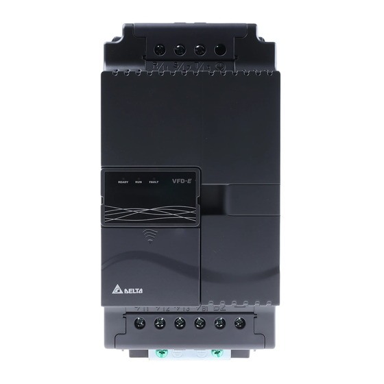
- Page 12 Internal Structure READY: power indicator FAULT READY RUN: status indicator 1 2 3 FAULT: fault indicator Switch to ON for 50Hz, refer to P 01.00 to P01.02 for details Switch to ON for free run to stop refer to P02.02 Switch to ON for setting frequency AVI2 source to ACI (P 02.00=2)
- Page 13 Frame B: above the nameplate Frame C (230V): near the input terminals Frame C (460V): near the input terminals (R/L1, S/L2, T/L3) (R/L1, S/L2, T/L3) Frame D: near the input terminals (R/L1, S/L2, T/L3), under terminal R/L1. Main power isolated from earth: If the AC motor drive is supplied from an isolated power (IT power), the RFI jumper must be cut off.
- Page 14 (according to IEC 61800-3) and reduce earth leakage current. CAUTION! 1. After applying power to the AC motor drive, do not cut off the RFI jumper. Therefore, make sure that main power has been switched off before cutting the RFI jumper. 2.
- Page 15 1.1.5 Remove Instructions Remove Keypad Remove RST Terminal Cover Press and hold in the latch on each side of For Frame B, C and D: it only needs to turn the cover then pull the cover up to release. cover lightly to open it. For Frame A, it doesn’t have cover and can be wired directly.
- Page 16 Remove Cooling Fan Press and hold in the latch on each side of the fan and pull the fan up to release. Frame A 3. Detach the power cord from the fan. 1. Press the left and right latches. 2. Remove the fan. Frame B 3.
- Page 17 Frame D 1. Press the left and right latches. 3. Detach the power cord from the fan. 2. Remove the fan. Remove Extension Card For Frame A, Frame B, Frame C and Frame D Loosen the screws first then press and hold in the latches on each side of the extension card and pull the extension card up to release.
-
Page 18: Preparation For Installation And Wiring
1.2 Preparation for Installation and Wiring 1.2.1 Ambient Conditions Install the AC motor drive in an environment with the following conditions: -10 ~ +50°C (14 ~ 122°F) for UL & cUL Air Temperature: -10 ~ +40°C (14 ~ 104°F) for side-by-side mounting Relative Humidity: <90%, no condensation allowed Atmosphere... - Page 19 Minimum Mounting Clearances Frame A Mounting Clearances Single drive Side-by-side installation Air flow 120mm 120mm Air Flow 120mm 120mm Frame B, C and D Mounting Clearances Single drive Side-by-side installation Air flow 150mm 150mm Air Flow 150mm 150mm 1-12...
- Page 20 For VFD-E-P series: heat sink system example Air-extracting apparatus User 's heat sink should comply with following conditions: Control panel Duct temperature Air flow speed 2m/sec 1. Flatness <0.1mm 2. Roughness <6um 3. Grease 10um~12um 4. Screw torque: 16Kgf-cm dust collector 5.
- Page 21 Installation with Metal Separation Installation without Metal Separation 1 20 mm 1 50 mm 1 20 mm 1 50 mm 1 20 mm 1 50 mm 1 20 mm 1 50 mm Air flow 1 50 mm 1 20 mm 1 50 mm 1 20 mm F ram e A...
- Page 22 VFD022E23A/C VFD037E23A/C VFD055E23A/C VFD075E23A/C VFD110E23A/C VFD150E23A/C VFD002E23P VFD004E23P VFD007E23P VFD015E23P 3φ/480V Model Total Power Dissipation (W) Flow rate (CFM) VFD004E43A/C/T Natural Convection VFD007E43A/C/T Natural Convection VFD015E43A/C/T VFD022E43A/C VFD037E43A/C VFD055E43A/C VFD075E43A/C VFD110E43 A/C VFD150E43 A/C VFD185E43 A/C VFD220E43 A/C VFD004E43P VFD007E43P VFD015E43P 1-15...
- Page 23 1.2.2 DC-bus Sharing: Connecting the DC-bus of the AC Motor Drives in Parallel This function is not for VFD-E-T series. The AC motor drives can absorb mutual voltage that generated to DC bus when deceleration. Enhance brake function and stabilize the voltage of the DC bus. The brake module can be added to enhance brake function after connecting in parallel.
-
Page 24: Dimensions
1.3 Dimensions Frame A VFD002E11A/11C/11T; VFD002E21A/21C/21T; VFD002E23A/23C/23T; VFD004E11A/11C/11T; VFD004E21A/21C/21T; VFD004E23A/23C/23T; VFD004E43A/43C/43T; VFD007E21A/21C/21T; VFD007E23A/23C/23T; VFD007E43A/43C/43T; Unit: mm [inch] Frame 72.0 60.0 142.0 120.0 152.0 50.0 [2.83] [2.36] [5.59] [4.72] [5.98] [1.97] [0.18] [0.20] [0.20] 1-17... - Page 25 Frame A VFD015E23A/23C/23T; VFD015E43A/43C/43T; Unit: mm [inch] Frame 72.0 60.0 142.0 120.0 152.0 50.0 [2.83] [2.36] [5.59] [4.72] [5.98] [1.97] [0.18] [0.20] [0.20] 1-18...
- Page 26 Frame A VFD002E11P/21P/23P; VFD004E11P/21P/23P/43P; VFD007E21P/23P/43P; VFD015E23P/43P; Unit: mm [inch] Frame 72.0 56.0 155.0 143.0 111.5 [2.83] [2.20] [6.10] [5.63] [4.39] [0.37] [0.21] 1-19...
- Page 27 Frame B VFD007E11A/11C; VFD015E21A/21C; VFD022E21A/21C; VFD022E23A/23C; VFD022E43A/43C; VFD037E23A/23C; VFD037E43A/43C; Unit: mm [inch] Frame 100.0 89.0 174.0 162.0 152.0 50.0 [3.94] [3.50] [6.86] [6.38] [5.98] [1.97] [0.16] [0.22] [0.22] 1-20...
- Page 28 Frame C VFD055E23A/23C; VFD055E43A/43C; VFD075E23A/23C; VFD075E43A/43C; VFD110E23A/23C; VFD110E43A/43C; Unit: mm [inch] Frame 130.0 116.0 260.0 246.5 169.2 78.5 [5.12] [4.57] [10.24] [9.70] [6.66] [3.09] [0.31] [0.26] [0.22] 1-21...
- Page 29 Frame D VFD150E23A/23C; VFD150E43A43C; VFD185E43A/43C; VFD220E43A/43C; Unit: mm [inch] Frame 200.0 180.0 310.0 290.0 190.0 92.0 10.0 10.0 [7.87] [7.09] [12.20] [11.42] [7.48] [3.62] [0.39] [0.39] [0.35] 1-22...
- Page 30 The "Line Fuse Specification" in Appendix B, lists the recommended fuse part number for each VFD-E Series part number. These fuses (or equivalent) must be used on all installations where compliance with U.L. standards is a required.
- Page 31 Chapter 2 Installation & Wiring DANGER! A charge may still remain in the DC bus capacitors with hazardous voltages even if the power has been turned off. To prevent personal injury, please ensure that the power is turned off and wait ten minutes for the capacitors to discharge to safe voltage levels before opening the AC motor drive.
- Page 32 RS-485 communication port or permanent damage may result. The pins 1 & 2 are the power supply for the optional copy keypad only and should not be used for RS-485 communication. Figure 1 for models of VFD-E Series VFD002E11A/21A, VFD004E11A/21A, VFD007E21A, VFD002E11C/21C, VFD004E11C/21C, VFD007E21C, VFD002E11P/21P, VFD004E11P/21P, VFD007E21P...
- Page 33 Chapter 2 Installation & Wiring Figure 2 for models of VFD-E Series VFD002E23A, VFD004E23A/43A, VFD007E23A/43A, VFD015E23A/43A, VFD002E23C, VFD004E23C/43C, VFD007E23C/43C, VFD015E23C/43C, VFD002E23P, VFD004E23P/43P, VFD007E23P/43P, VFD015E23P/43P...
- Page 34 Chapter 2 Installation & Wiring Figure 3 for models of VFD-E Series VFD007E11A, VFD015E21A, VFD022E21A, VFD007E11C, VFD015E21C, VFD022E21C...
- Page 35 Chapter 2 Installation & Wiring Figure 4 for models of VFD-E Series VFD022E23A/43A, VFD037E23A/43A, VFD055E23A/43A, VFD075E23A/43A, VFD110E23A/43A, VFD022E23C/43C, VFD037E23C/43C, VFD055E23C/43C, VFD075E23C/43C, VFD110E23C/43C, VFD150E23A/23C, VFD150E43A/43C, VFD185E43A/43C, VFD220E43A/43C...
- Page 36 Chapter 2 Installation & Wiring Figure 5 for models of VFD-E Series VFD002E11T/21T, VFD004E11A/21T, VFD007E21T...
- Page 37 Chapter 2 Installation & Wiring Figure 6 for models of VFD-E Series VFD002E23T, VFD004E23T/43T, VFD007E23T/43T, VFD015E23T/43T...
- Page 38 Chapter 2 Installation & Wiring Figure 7 Wiring for NPN mode and PNP mode A. NPN mode without external power PN P Factory setting B. NPN mode with external power PN P Factory setting C. PNP mode without external power Factory setting...
- Page 39 Chapter 2 Installation & Wiring D. PNP mode with external power NP N PN P Factory setting Figure 8 Pin definition for VFD*E*C CANopen models (Note: CANopen models can’t use PU06) Signal Description CAN_H CAN_H bus line (dominant high) CAN_L CAN_L bus line (dominant low) CAN_GND Ground / 0V /V-...
- Page 40 Use ground leads that comply with local regulations and keep them as short as possible. No brake resistor is built in the VFD-E series, it can install brake resistor for those occasions that use higher load inertia or frequent start/stop. Refer to Appendix B for details.
- Page 41 Chapter 2 Installation & Wiring Multiple VFD-E units can be installed in one location. All the units should be grounded directly to a common ground terminal, as shown in the figure below. Ensure there are no ground loops. Excellent Good Not allowed 2-12...
-
Page 42: External Wiring
Chapter 2 Installation & Wiring 2.2 External Wiring Items Explanations Power Supply Please follow the specific power Power supply requirements shown in supply Appendix A. There may be an inrush current during power up. Please check the FUSE/NFB Fuse/NFB chart of Appendix B and select the (Optional) correct fuse with rated current. -
Page 43: Main Circuit
Chapter 2 Installation & Wiring 2.3 Main Circuit 2.3.1 Main Circuit Connection Figure 1 For frame A: VFD002E11A/21A/23A, VFD004E11A/21A/23A/43A, VFD007E21A/23A/43A, VFD002E11C/21C/23C, VFD004E11C/21C/23C/43C, VFD007E21C/23C/43C, VFD002E11P/21P/23P, VFD004E11P/21P/23P/43P, VFD007E21P, VFD015E23A/43A /23P /43P Brake Resistor(Optional) Brake Unit (Optional) No fuse breaker (NFB) Motor R(L1) U(T1) S(L2) V(T2) - Page 44 Chapter 2 Installation & Wiring Terminal Symbol Explanation of Terminal Function R/L1, S/L2, T/L3 AC line input terminals (1-phase/3-phase) U/T1, V/T2, W/T3 AC drive output terminals for connecting 3-phase induction motor +/B1~ B2 Connections for Brake resistor (optional) +/B1, - Connections for External Brake unit (BUE series) Earth connection, please comply with local regulations.
- Page 45 AC motor drive. Please use inductance filter. Do not use phase-compensation capacitors or L-C (Inductance-Capacitance) or R-C (Resistance-Capacitance), unless approved by Delta. DO NOT connect phase-compensation capacitors or surge absorbers at the output terminals of AC motor drives.
- Page 46 Chapter 2 Installation & Wiring 2.3.2 Main Circuit Terminals Frame A Main circuit terminals: R/L1, S/L2, T/L3, U/T1, V/T2, W/T3, , +, - Wire Models Wire Torque Type VFD002E11A/11C/11T/11P; VFD002E21A/21C/21T/21P; Stranded VFD002E23A/23C/23T/23P; VFD004E11A/11C/11T/11P; copper VFD004E21A/21C/21T/21P; 8 kgf-cm only VFD004E23A/23C/23T/23P; 14 AWG. VFD004E43A/43C/43T/43P;...
- Page 47 Chapter 2 Installation & Wiring Frame C Main circuit terminals: R/L1, S/L2, T/L3, U/T1, V/T2, W/T3, , +/B1, B2, - Wire Wire Models Wire (Min.) Torque (Max.) Type VFD055E23A/23C 8 AWG (8.4mm VFD075E23A/23C 8 AWG (8.4mm Stranded copper only VFD110E23A/23C 6 AWG (13.3mm 6 AWG 30kgf-cm 600V ,...
-
Page 48: Control Terminals
Chapter 2 Installation & Wiring 2.4 Control Terminals Circuit diagram for digital inputs (NPN current 16mA.) PNP Mode NPN Mode Multi-Input multi-input Terminal terminal +24V Internal Circuit Internal Circuit The position of the control terminals AFM MCM MO1 RS-485 DCM 24V ACM AVI ACI MI1 MI2 MI3 MI4 MI5 MI6 Terminal symbols and functions... - Page 49 Chapter 2 Installation & Wiring Factory Settings (NPN mode) Terminal Terminal Function Symbol ON: Connect to DCM Common for digital inputs and used for NPN Digital Signal Common mode. Resistive Load: Multi-function Relay output (N.O.) a 5A(N.O.)/3A(N.C.) 240VAC 5A(N.O.)/3A(N.C.) 24VDC Multi-function Relay output Inductive Load: (N.C.) b...
- Page 50 Chapter 2 Installation & Wiring Factory Settings (NPN mode) Terminal Terminal Function Symbol ON: Connect to DCM ACI circuit Set-up: Pr.04.15 ~ Pr.04.18 internal circuit Analog output meter 0 to 10V, 2mA ACM circuit Impedance: 100kΩ Output current 2mA max 0~10V Resolution: 8 bits...
- Page 51 Chapter 2 Installation & Wiring General Keep control wiring as far away as possible from the power wiring and in separate conduits to avoid interference. If necessary let them cross only at 90º angle. The AC motor drive control wiring should be properly installed and not touch any live power wiring or terminals.
-
Page 52: Keypad
Chapter 3 Keypad and Start Up Chapter 3 Keypad and Start Up Make sure that the wiring is correct. In particular, check that the output terminals U/T1, V/T2, W/T3. are NOT connected to power and that the drive is well grounded. ... -
Page 53: Operation Method
Chapter 3 Keypad and Start Up 3.2 Operation Method The operation method can be set via communication, control terminals and optional keypad KPE- LE02. A) Connect RS-485 communication port. Use a VFD-USB01 cable or an IFD8500 (IFD6500) communication module to connect your computer to this port. B) Control terminals MI~ M6. -
Page 54: Trial Run
Chapter 3 Keypad and Start Up Operation Operation Command Frequency Source Method Source When setting communication by the PC, it needs to use VFD-USB01 or Operate from the IFD8500 converter to connect to the PC. communication Refer to the communication address 2000H and 2101H setting for details. ... - Page 55 Chapter 3 Keypad and Start Up Setting the potentiometer or AVI-DCM 0-10Vdc power to less than 1V. Setting MI1=On for forward running. And if you want to change to reverse running, you should set MI2=On. And if you want to decelerate to stop, please set MI1/MI2=Off. Check following items: ...
- Page 56 Chapter 4 Parameters Chapter 4 Parameters The VFD-E parameters are divided into 14 groups by property for easy setting. In most applications, the user can finish all parameter settings before start-up without the need for re-adjustment during operation. The 14 groups are as follows: Group 0: User Parameters Group 1: Basic Parameters Group 2: Operation Method Parameters...
-
Page 57: Summary Of Parameter Settings
Chapter 4 Parameters 4.1 Summary of Parameter Settings : The parameter can be set during operation. Group 0 User Parameters Factory Parameter Explanation Settings Customer Setting 00.00 Identity Code of the Read-only AC motor drive 00.01 Rated Current Read-only Display of the AC motor drive 0: Parameter can be read/written... - Page 58 Chapter 4 Parameters Factory Parameter Explanation Settings Customer Setting 4: Display output voltage (E) 5: Display PID analog feedback signal value (b) (%) 6: Output power factor angle (n) 7: Display output power (P) 8: Display the estimated value of torque as it relates to current (t) 9: Display AVI (I) (V) 10: Display ACI / AVI2 (i) (mA/V)
- Page 59 Chapter 4 Parameters Group 1 Basic Parameters Factory Parameter Explanation Settings Customer Setting Maximum Output 50.00 to 599.00 Hz 01.00 60.00 Frequency (Fmax) Maximum Voltage 01.01 Frequency (Fbase) 0.10 to 599.00 Hz 60.00 (Motor 0) Maximum Output 115V/230V series: 0.1V to 255.0V 220.0 01.02 Voltage (Vmax)
- Page 60 Chapter 4 Parameters Factory Parameter Explanation Settings Customer Setting deceleration (refer 1: Auto Accel, Linear Decel to Accel/Decel time 2: Linear Accel, Auto Decel setting) 3: Auto Accel/Decel (Set by load) 4: Auto Accel/Decel (set by Accel/Decel Time setting) Auto acceleration / 5: Linear Accel.
- Page 61 Chapter 4 Parameters Factory Parameter Explanation Settings Customer Setting Maximum Output 115V/230V series: 0.1V to 255.0V 220.0 01.33 Voltage (Vmax) 460V series: 0.1V to 510.0V 440.0 (Motor 2) Mid-Point 0.10 to 599.00 Hz Frequency (Fmid) 01.34 1.50 (Motor 2) 115V/230V series: 0.1V to 255.0V 10.0 Mid-Point Voltage...
- Page 62 Chapter 4 Parameters Group 2 Operation Method Parameters Factory Parameter Explanation Settings Customer Setting 0: Digital keypad UP/DOWN keys or Multi- function Inputs UP/DOWN. Last used frequency saved. Source of First 1: 0 to +10V from AVI 02.00 Master Frequency 2: 4 to 20mA from ACI or 0 to +10V from Command AVI2...
- Page 63 Chapter 4 Parameters Factory Parameter Explanation Settings Customer Setting 0: Start running when Power is on. 1: Don’t run when Power is on 2: When the source of the command changes, VFD’s operation remains the The source of same. Power-On command and Running 3: When the source of the command...
- Page 64 Chapter 4 Parameters Factory Parameter Explanation Settings Customer Setting 0.00 to 599.00Hz Keypad Frequency 60.00 02.11 Command Communication 0.00 to 599.00Hz Frequency 60.00 02.12 Command 0: Save Keypad & Communication The Selections for Frequency Saving Keypad or 02.13 Communication 1: Save Keypad Frequency only Frequency 2: Save Communication Frequency only...
- Page 65 Chapter 4 Parameters Group 3 Output Function Parameters Factory Parameter Explanation Settings Customer Setting 0: No function Multi-function 1: AC drive operational 03.00 Output Relay (RA1, 2: Master frequency attained RB1, RC1) 3: Zero speed 4: Over torque detection 5: Base-Block (B.B.) indication Multi-function 6: Low-voltage indication...
- Page 66 Chapter 4 Parameters Factory Parameter Explanation Settings Customer Setting Preliminary Count 03.06 0 to 9999 Value 0: Terminal count value attained, no EF EF Active When display 03.07 Terminal Count Value Attained 1: Terminal count value attained, EF active 0: Fan always ON 1: 1 minute after AC motor drive stops, fan will be OFF...
- Page 67 Chapter 4 Parameters Factory Parameter Explanation Settings Customer Setting Read only Bit0: RLY Status Bit1: MO1 Status Bit2: MO2/RA2 Status Display the Status of 03.13 Multi-function Bit3: MO3/RA3 Status Output Terminals Bit4: MO4/RA4 Status Bit5: MO5/RA5 Status Bit6: MO6/RA6 Status Bit7: MO7/RA7 Status Desired Frequency 0.00 to 599.00Hz...
- Page 68 Chapter 4 Parameters Group 4 Input Function Parameters Factory Parameter Explanation Settings Customer Setting Keypad 0.0 to 200.0 % 04.00 Potentiometer Bias Keypad 0: Positive bias Potentiometer Bias 04.01 1: Negative bias Polarity Keypad 0.1 to 200.0 % 100.0 04.02 Potentiometer Gain Keypad...
- Page 69 Chapter 4 Parameters Factory Parameter Explanation Settings Customer Setting 16: Output shutoff stop 17: Parameter lock enable 18: Operation command selection (external terminals) 19: Operation command selection(keypad) 20: Operation command selection (communication) 21: FWD/REV command 22: Source of second frequency command 23: Run/Stop PLC Program (PLC1) (NOT for VFD*E*C models) 23: Quick Stop (Only for VFD*E*C models)
- Page 70 Chapter 4 Parameters Factory Parameter Explanation Settings Customer Setting 04.20 Min AVI2 Voltage 0.0 to 10.0V 04.21 Min AVI2 Frequency 0.0 to 100.0% F max. 04.22 Max AVI2 Voltage 0.0 to 10.0V 10.0 Max AVI2 04.23 0.0 to 100.0% F max. 100.0 Frequency Read only...
- Page 71 Chapter 4 Parameters Factory Parameter Explanation Settings Customer Setting Bit5: MI6 Status Bit6: MI7 Status Bit7: MI8 Status Bit8: MI9 Status Bit9: MI10 Status Bit10: MI11 Status Bit11: MI12 Status Internal/External 0~4095 04.27 Multi-function Input Terminals Selection Internal Terminal 0~4095 04.28 Status...
- Page 72 Chapter 4 Parameters Group 5 Multi-Step Speeds Parameters Factory Parameter Explanation Settings Customer Setting 1st Step Speed 0.00 to 599.00 Hz 0.00 05.00 Frequency 2nd Step Speed 0.00 to 599.00 Hz 0.00 05.01 Frequency 3rd Step Speed 0.00 to 599.00 Hz 0.00 05.02 Frequency...
- Page 73 Chapter 4 Parameters Factory Parameter Explanation Settings Customer Setting 15th Step Speed 0.00 to 599.00 Hz 0.00 05.14 Frequency 4-18...
- Page 74 Chapter 4 Parameters Group 6 Protection Parameters Factory Parameter Explanation Settings Customer Setting 115/230V series: 330.0V to 410.0V 390.0V Over-Voltage Stall 06.00 460V series: 660.0V to 820.0V 780.0V Prevention 0.0: Disable over-voltage stall prevention Over-Current Stall 0:Disable 06.01 Prevention during 20 to 250% Accel Over-Current Stall...
- Page 75 Chapter 4 Parameters Factory Parameter Explanation Settings Customer Setting 4: Reserved 5: Overload (oL) 6: Overload1 (oL1) 7: Motor over load (oL2) 06.09 Second Most 8: External fault (EF) Recent Fault Record 9: Current exceeds 2 times rated current during accel.(ocA) 10: Current exceeds 2 times rated current during decel.(ocd)
- Page 76 Chapter 4 Parameters Factory Parameter Explanation Settings Customer Setting 31: Control Board CPU WRITE failure (cF2.1) 32: ACI signal fault (AErr) 33: Reserved 34: Motor PTC overheat protection (PtC1) 35: PG feedback signal fault (PGEr) 36-39: Reserved 40: Communication time-out fault of control board and power board (CP10) 41: dEb fault 42: ACL (Abnormal Communication Loop)
- Page 77 Chapter 4 Parameters Group 7 Motor Parameters Factory Parameter Explanation Settings Customer Setting 07.00 Motor Rated Current 30 %FLA to 120% FLA (Motor 0) Motor No-Load 0%FLA to 99% FLA 0.4*FLA 07.01 Current (Motor 0) Torque Compensation 0.0 to 10.0 07.02 (Motor 0) Slip Compensation...
- Page 78 07.15 Overheat Warning 0.1~10.0V Level Motor PTC 07.16 Overheat Reset 0.1~5.0V Delta Level 0: Warn and RAMP to stop Treatment of the 07.17 Motor PTC 1: Warn and COAST to stop Overheat 2: Warn and keep running Motor Rated Current 07.18...
- Page 79 Chapter 4 Parameters Factory Parameter Explanation Settings Customer Setting Motor Line-to-line 0~65535 mΩ 07.29 Resistance R1 (Motor 2) Motor Rated Slip 07.30 0.00 to 20.00 Hz 3.00 (Motor 2) Motor Pole Number 07.31 2 to 10 (Motor 3) Motor Rated Current 07.32 30 %FLA to 120% FLA (Motor 3)
- Page 80 Chapter 4 Parameters Group 8 Special Parameters Factory Parameter Explanation Settings Customer Setting DC Brake Current 08.00 0 to 100% Level DC Brake Time 08.01 0.0 to 60.0 sec during Start-Up DC Brake Time 08.02 0.0 to 60.0 sec during Stopping Start-Point for DC 0.00 to 599.00 Hz...
- Page 81 Chapter 4 Parameters Factory Parameter Explanation Settings Customer Setting Skip Frequency 3 0.00 to 599.00 Hz 08.13 0.00 Upper Limit Skip Frequency 3 0.00 to 599.00 Hz 08.14 0.00 Lower Limit Auto Restart After 0 to 10 (0=disable) 08.15 Fault 0.1 to 6000 sec Auto Reset Time at...
- Page 82 Chapter 4 Parameters Group 9 Communication Parameters Factory Parameter Explanation Settings Customer Setting Communication 1 to 254 09.00 Address 0: Baud rate 4800bps 1: Baud rate 9600bps Transmission Speed 09.01 2: Baud rate 19200bps 3: Baud rate 38400bps 0: Warn and keep operating 1: Warn and ramp to stop Transmission Fault 09.02...
- Page 83 Chapter 4 Parameters Factory Parameter Explanation Settings Customer Setting 0: Baud rate 4800 bps 1: Baud rate 9600 bps Transmission Speed 2: Baud rate 19200 bps 09.08 for USB Card 3: Baud rate 38400 bps 4: Baud rate 57600 bps 0: 7,N,2 for ASCII 1: 7,E,1 for ASCII 2: 7,O,1 for ASCII...
- Page 84 Chapter 4 Parameters Group 10 PID Control Parameters Factory Parameter Explanation Settings Customer Setting 0: Disable PID operation 1: Keypad (based on Pr.02.00) PID Set Point 2: 0 to +10V from AVI 10.00 Selection 3: 4 to 20mA from ACI or 0 to +10V from AVI2 4: PID set point (Pr.10.11) 0: Positive PID feedback from external...
- Page 85 Chapter 4 Parameters Factory Parameter Explanation Settings Customer Setting Source of PID Set 0.00 to 599.00 Hz 10.11 0.00 point 10.12 PID Offset Level 1.0 to 50.0% 10.0 Detection Time of 10.13 0.1 to 300.0 sec PID Offset Sleep/Wake Up 10.14 0.0 to 6550 sec Detection Time...
- Page 86 Chapter 4 Parameters Group 11 Parameters for Extension Card Factory Parameter Explanation Settings Customer Setting 0: No function Multi-function 1: AC drive operational 11.00 Output Terminal 2: Master frequency attained MO2/RA2 3: Zero speed 4: Over torque detection Multi-function 5: Base-Block (B.B.) indication 11.01 Output Terminal...
- Page 87 Chapter 4 Parameters Factory Parameter Explanation Settings Customer Setting 0: No function Multi-function Input 11.06 1: Multi-Step speed command 1 Terminal (MI7) 2: Multi-Step speed command 2 3: Multi-Step speed command 3 Multi-function Input 11.07 4: Multi-Step speed command 4 Terminal (MI8) 5: External reset 6: Accel/Decel inhibit...
- Page 88 Chapter 4 Parameters Factory Parameter Explanation Settings Customer Setting 25: Simple position function 26: OOB (Out of Balance Detection) 27: Motor selection (bit 0) 28: Motor selection (bit 1) 4-33...
- Page 89 Chapter 4 Parameters Group 12: Analog Input/ Output Parameters for Extension Card Factory Parameter Explanation Settings Customer Setting 0: Disabled 1: Source of the 1st frequency 2: Source of the 2nd frequency AI1 Function 12.00 Selection 3: PID Set Point (PID enable) 4: Positive PID feedback 5: Negative PID feedback 0: ACI2 analog current (0.0 ~ 20.0mA)
- Page 90 Chapter 4 Parameters Factory Parameter Explanation Settings Customer Setting Min. AVI4 Input 12.12 0.0 to 10.0V Voltage Min. AVI4 Scale 12.13 0.0 to 100.0% Percentage Max. AVI4 Input 12.14 0.0 to 10.0V 10.0 Voltage Max. AVI4 Scale 12.15 0.0 to 100.0% 100.0 Percentage Min.
- Page 91 Chapter 4 Parameters Factory Parameter Explanation Settings Customer Setting AUI Analog Input 0.00~200.00% 0.00 12.27 Bias 0: Positive bias 12.28 AUI Bias Polarity 1: Negative bias AUI Analog Gain 1~200% 12.29 0: No AUI Negative Bias Command AUI Negative Bias, 12.30 Reverse Motion 1: Negative Bias: REV Motion Enabled...
- Page 92 Chapter 4 Parameters Group 13: PG function Parameters for Extension Card Factory Parameter Explanation Settings Customer Setting 0: Disabled 1: Single phase 13.00 PG Input 2: Forward/Counterclockwise rotation 3: Reverse/Clockwise rotation 13.01 PG Pulse Range 1 to 20000 Motor Pole Number 13.02 2 to 10 (Motor 0)
-
Page 93: Parameter Settings For Applications
Chapter 4 Parameters 4.2 Parameter Settings for Applications Speed Search Related Applications Purpose Functions Parameters Windmill, winding Restart free- Before the free-running motor is 08.04~08.08 machine, fan and all running motor completely stopped, it can be restarted inertia loads without detection of motor speed. - Page 94 Chapter 4 Parameters Overheat Warning Related Applications Purpose Functions Parameters When AC motor drive overheats, it 03.00~03.01 Air conditioner Safety measure uses a thermal sensor to have 04.05~04.08 overheat warning. Two-wire/three-wire Related Applications Purpose Functions Parameters 02.01 MI1:("OPEN":STOP) FWD/STOP ("CLOSE":FWD) 04.04 MI2:("OPEN": STOP)
- Page 95 Chapter 4 Parameters Auto Restart after Fault Related Applications Purpose Functions Parameters For continuous and 08.15~08.16 The AC motor drive can be Air conditioners, reliable operation restarted/reset automatically up to 10 remote pumps without operator times after a fault occurs. intervention Emergency Stop by DC Brake Related...
- Page 96 Chapter 4 Parameters Carrier Frequency Setting Related Applications Purpose Functions Parameters The carrier frequency can be 02.03 General application Low noise increased when required to reduce motor noise. Keep Running when Frequency Command is Lost Related Applications Purpose Functions Parameters When the frequency command is lost 02.06...
- Page 97 Chapter 4 Parameters Output Signal for Base Block Related Applications Purpose Functions Parameters When executing Base Block, a signal 03.00~03.01 Provide a signal for General application is given for external system or control running status wiring. Overheat Warning for Heat Sink Related Applications Purpose...
-
Page 98: Description Of Parameter Settings
Chapter 4 Parameters 4.3 Description of Parameter Settings Group 0: User Parameters This parameter can be set during operation Identity Code of the AC Motor Drive 00.00 Settings Read Only Factory setting: ## Rated Current Display of the AC Motor Drive 00.01 Settings Read Only... - Page 99 Chapter 4 Parameters Parameter Reset 00.02 Factory Setting: 0 Settings 0 Parameter can be read/written All parameters are read-only Clear PLC program (NOT for VFD*E*C models) Keypad Lock All parameters are reset to factory settings (50Hz, 230V/400V or 220V/380V depends on Pr.00.12) All parameters are reset to factory settings (60Hz, 115V/220V/440V) ...
- Page 100 Chapter 4 Parameters Content of Multi-function Display 00.04 Factory Setting: 0 Settings 0 Display the content of user-defined unit (Uxxx) Display the counter value which counts the number of pulses on TRG terminal (c) Display PLC D1043 value (C) (NOT for VFD*E*C models) Display the actual DC BUS voltage in VDC of the AC motor drive (u)
- Page 101 Chapter 4 Parameters User Defined Coefficient K 00.05 Settings 0. 1 to 160.0 Factory Setting: 1.0 The coefficient K determines the multiplying factor for the user-defined unit. When Pr00.04 is set to 0: User-defined unit (U) = Output frequency (H) * User Defined Coefficient (K) ...
- Page 102 Chapter 4 Parameters Decode 00.08 input passw ord If the password is corr ec t? D isplays 0 when 3 c hanc es to enter the corr ect enter ing cor rect passw ord. password into 1st time displays "1" if Pr.00.08.
- Page 103 Chapter 4 Parameters Control Method 00.10 Factory Setting: 0 Settings V/f Control Vector Control This parameter determines the control method of the AC motor drive. Control of V/f (Voltage/frequency) 1. To operate by the change of frequency and voltage without changing the mechanical characteristic of motor: it can run by open-loop method and also can use with PG card (refer to Appendix B) to run by close-loop method.
- Page 104 Chapter 4 Parameters Group 1: Basic Parameters Maximum Output Frequency (Fmax) Unit: Hz 01.00 Settings 50.00 to 599.00 Hz Factory Setting: 60.00 This parameter determines the AC motor drive’s Maximum Output Frequency. All the AC motor drive frequency command sources (analog inputs 0 to +10V and 4 to 20mA) are scaled to correspond to the output frequency range.
- Page 105 Chapter 4 Parameters Maximum Output Voltage (Vmax) (Motor 0) Unit: V 01.02 Settings 115V/230V series 0.1 to 255.0V Factory Setting: 220.0 460V series 0.1 to 510.0V Factory Setting: 440.0 This parameter determines the Maximum Output Voltage of the AC motor drive. The Maximum Output Voltage setting must be smaller than or equal to the rated voltage of the motor as indicated on the motor nameplate.
- Page 106 Chapter 4 Parameters Minimum Output Frequency (Fmin) (Motor 0) Unit: Hz 01.05 Settings 0.10 to 599.00Hz Factory Setting: 1.50 This parameter sets the Minimum Output Frequency of the AC motor drive. If the frequency command is greater than this setting, the AC motor drive will accelerate to the frequency command by the accel./decel.
- Page 107 Chapter 4 Parameters Vol tage 0 1.0 2 Maximum Output Vol tage ( Vbas e) 0 1.0 4 Mid-point Vol tage ( Vmid) 0 1.0 6 F requenc y Minimum 0 1.0 3 0 1.0 1 0 1.0 0 0 1.0 5 Output Maximum Voltage...
- Page 108 Chapter 4 Parameters Output frequency 01.07 Output frequency upper l imit 01.08 Output frequency F requenc y low er limit command Acceleration Time 1 (Taccel 1) Unit: second 01.09 Deceleration Time 1 (Tdecel 1) Unit: second 01.10 Acceleration Time 2 (Taccel 2) Unit: second 01.11 Deceleration Time 2 (Tdecel 2)
- Page 109 Chapter 4 Parameters Frequency 01.00 Max. output Frequency setting operation frequency 01.05 Time Min. output frequency Accel. Time Decel. Time 01.11 01.12 01.09 01.10 The definition of Accel./Decel. Time Accel/Decel Time Unit 01.19 Factory Setting: 0 Settings Unit: 0.1 sec Unit: 0.01 sec ...
- Page 110 Chapter 4 Parameters Jog Acceleration Time Unit: second 01.13 Settings 0.1 to 600.0/0.01 to 600.0 sec Factory Setting: 1.0 Jog Deceleration Time Unit: second 01.14 Settings 0.1 to 600.0/0.01 to 600.0 sec Factory Setting: 1.0 Jog Frequency Unit: Hz 01.15 Settings 0.10 to 599.00Hz...
- Page 111 Chapter 4 Parameters With Auto acceleration / deceleration it is possible to reduce vibration and shocks during starting/stopping the load. When Pr.01.16 is set to 3 Auto acceleration / deceleration (set by load): During Auto acceleration the torque is automatically measured and the drive will accelerate to the set frequency with the fastest acceleration time and the smoothest starting current.
- Page 112 Chapter 4 Parameters The total Accel. Time=Pr.01.09 + Pr.01.17 or Pr.01.11 + Pr.01.17 The total Decel. Time=Pr.01.10 + Pr.01.18 or Pr.01.12 + Pr.01.18 Disable S curve Enable S curve Acceleration/deceleration Characteristics Related parameters: Pr.01.09(Accel Time 1), Pr.01.10(Decel Time 1), Pr.01.11(Accel Time 2) and Pr.01.12(Decel Time 2).
- Page 113 Chapter 4 Parameters Assume that the radius of the 4-pole motor is r and rotation speed is n (rpm). Example 1: Assume that motor speed is 50Hz, the delay time at 50Hz is 2 sec (Pr.01.25=2) and the deceleration time from 50Hz to 0Hz is 10 seconds.
- Page 114 Chapter 4 Parameters 460V series 0.1 to 510.0V Factory Setting: 440.0 Mid-Point Frequency (Fmid) (Motor 1) Unit: Hz 01.28 Settings 0.10 to 599.00Hz Factory Setting: 1.50 Mid-Point Voltage (Vmid) (Motor 1) Unit: V 01.29 Settings 115V/230V series 0.1 to 255.0V Factory Setting: 10.0 460V series 0.1 to 510.0V...
- Page 115 Chapter 4 Parameters Mid-Point Frequency (Fmid) (Motor 3) Unit: Hz 01.40 Settings 0.10 to 599.00Hz Factory Setting: 1.50 Mid-Point Voltage (Vmid) (Motor 3) Unit: V 01.41 Settings 115V/230V series 0.1 to 255.0V Factory Setting: 10.0 460V series 0.1 to 510.0V Factory Setting: 20.0 Minimum Output Frequency (Fmin) (Motor 3) Unit: Hz...
- Page 116 Chapter 4 Parameters Group 2: Operation Method Parameters Source of First Master Frequency Command 02.00 Factory Setting: 1 Source of Second Master Frequency Command 02.09 Factory Setting: 0 Settings Digital keypad UP/DOWN keys or Multi-function Inputs UP/DOWN. Last used frequency saved. (Digital keypad is optional) 0 to +10V from AVI 4 to 20mA from ACI or 0 to +10V from AVI2 RS-485 (RJ-45)/USB communication...
- Page 117 Chapter 4 Parameters When the AC motor drive is controlled by external terminal, please refer to Pr.02.05/Pr.04.04 for details. Combination of the First and Second Master Frequency 02.10 Command Factory Setting: 0 Settings First Master Frequency Command Only First Master Frequency + Second Master Frequency First Master Frequency - Second Master Frequency It can be used to add or subtract the first frequency set in Pr.02.00 and the second frequency...
- Page 118 Chapter 4 Parameters It is recommended to use “ramp to stop” for safety of personnel or to prevent material from being wasted in applications where the motor has to stop after the drive is stopped. The deceleration time has to be set accordingly. If motor free running is allowed or the load inertia is large, it is recommended to select “coast to stop”.
- Page 119 Chapter 4 Parameters Frequency Frequency frequency output motor speed frequency motor output speed stops according to free run to stop decel eration time operation operation command command When Pr.02.02 is set to 0 or 1 When Pr.02.02 is set to 2 or 3 PWM Carrier Frequency Selections Unit: Hz 02.03...
- Page 120 Chapter 4 Parameters Motor Direction Control 02.04 Factory Setting: 0 Settings Forward/Reverse operation enabled Reverse operation disabled Forward operation disabled This parameter is used to disable one direction of rotation of the AC motor drive direction of rotation to prevent damage due to operation faults. ...
- Page 121 Chapter 4 Parameters Change according to the new Enable (AC motor drive doesn’t run) operation command source Changes as the external terminal’s Disable (AC motor drive will run) status changes When the operation command source is from external terminal and operation command is ON (NPN mode: MI1/MI2-DCM=closed, PNP mode: MI1/MI2+24V=closed, please refer to chapter 2 wiring for details), the AC motor drive will operate according to Pr.02.05 after power is applied.
- Page 122 Chapter 4 Parameters When Pr.02.05 is set to 1 or 3, it does not guarantee that the motor will never run under this condition. It is possible the motor may be set in motion by a malfunctioning switch. ...
- Page 123 Chapter 4 Parameters When Pr.02.07 is set to 0, it uses the external terminals UP/DOWN key to increase/decrease the frequency (F) as shown at the right of the following figure. Its function is the same as the UP/DOWN key on the digital keypad. In this mode, it also can use UP/DOWN key on the keypad to control.
- Page 124 Chapter 4 Parameters Frequency frequency command by Pr.02.08 setting Time multi -function input set to 10 (UP command) Related parameters: Pr.02.08(Accel/Decel Rate of Change of UP/DOWN Operation with Constant Speed), Pr.04.05(Multi-function Input Terminal (MI3)), Pr.04.06(Multi-function Input Terminal (MI4)), Pr.04.07(Multi-function Input Terminal (MI5)), Pr.04.08(Multi-function Input Terminal (MI6)) Accel/Decel Rate of Change of UP/DOWN Operation with Unit: Hz/2ms...
- Page 125 Chapter 4 Parameters Setting 0: After the AC motor drive is power off, save keypad and communication frequency in the AC motor drive. Setting 1: After the AC motor drive is power off, only save keypad frequency in the AC motor drive and won’t save communication frequency.
- Page 126 Chapter 4 Parameters speed command 2), 3(Multi-Step speed command 3), 4(Multi-Step speed command 4), 8(Jog Operation), 10(Up: Increment master frequency) and 11(Down: Decrement master frequency), it displays 4 in Pr.02.16. Pr.04.05(Multi-function Input Terminal (MI3)), Pr.04.06(Multi-function Input Terminal (MI4)), Pr.04.07(Multi-function Input Terminal (MI5)), Pr.04.08(Multi-function Input Terminal (MI6)) 4-71...
- Page 127 Chapter 4 Parameters Display the Operation Command Source 02.17 Settings Read Only Factory display: 4 You can read the operation source by this parameter. Display Value Function Bit0=1 Operation Command Source by Digital Keypad Bit1=1 Operation Command Source by RS485 communication Bit2=1 Operation Command Source by External Terminal Bit3=1...
- Page 128 Chapter 4 Parameters Selection for Carrier Modulation 02.18 Factory Setting: 0 Settings By carrier modulation of load current and temperature By carrier modulation of load current Setting 0: The PWM carrier frequency (Fc) will be decreased automatically by heat sink temperature and output current of the AC motor drive.
- Page 129 Chapter 4 Parameters with mounting method A ℃ 100% with mounting method B ℃ with mounting method A ℃ with mounting method B ℃ with mounting method A ℃ with mounting method B ℃ Carrier 2kHz 6kHz 10kHz 14kHz 15kHz Frequency 4kHz 8kHz...
- Page 130 Chapter 4 Parameters 10 11 12 13 14 15 Carri er frequency (k Hz ) Selection of Zero speed control mode 02.19 Factory Setting: 0 Settings Enter standby mode when zero speed Run DC brake when zero speed(the max. output voltage *0.05 ) 4-75...
- Page 131 Chapter 4 Parameters Group 3: Output Function Parameters Multi-function Output Relay (RA1, RB1, RC1) 03.00 Factory Setting: 8 Multi-function Output Terminal MO1 03.01 Factory Setting: 1 Settings Function Description No Function AC Drive Operational Active when the drive is ready or RUN command is “ON”. Master Frequency (F) Active when the output frequency(H) of AC motor drive Attained...
- Page 132 Chapter 4 Parameters Settings Function Description Over Voltage Stall Active when the Over Voltage Stall function(Pr.06.00) supervision operating Over Current Stall Active when the Over Current Stall function(Pr.06.01, supervision Pr.06.02) operating When IGBT overheats, it will signal to prevent OH turn off IGBT Overheat Warning the drive.
- Page 133 Chapter 4 Parameters Desired Frequency 1 Attained Unit: 0.01 03.02 Desired Frequency 2 Attained Unit: 0.01 03.14 Settings 0.00 to 599.00 Hz Factory Setting: 0.00 If a multi-function output terminal is set to function as Desired Frequency Attained 1(Pr.03.00 to Pr.03.01=09), then the output will be activated when the output frequency reaches Pr.03.02 setting.
- Page 134 Chapter 4 Parameters Analog Output Gain Unit: % 03.04 Settings 1 to 200% Factory Setting: 100 This parameter sets the voltage range of the analog output signal AFM. When Pr.03.03 is set to 0, the analog output voltage is directly proportional to the output ...
- Page 135 Chapter 4 Parameters 2msec Display (Pr.00.04=1) Counter Trigger 2msec The width of trigger signal Preliminary Count Value should not be less than (Pr. 03.00~Pr. 03.01=11) 2ms(<250 Hz) Ex:03.05=5,03.06=3 Terminal Count Value (Pr. 03.00~Pr. 03.01=10) EF Active when Terminal Count Value Attained 03.07 Factory Setting: 0 Settings...
- Page 136 Chapter 4 Parameters The Digital Output Used by PLC (NOT for VFD*E*C models) 03.09 Settings Read Only Factory display: 0 Bit0=1: RLY used by PLC Bit1=1: MO1 used by PLC Bit2=1: MO2/RA2 used by PLC Bit3=1: MO3/RA3 used by PLC Bit4=1: MO4/RA4 used by PLC Bit5=1: MO5/RA5 used by PLC Bit6=1: MO6/RA6 used by PLC...
- Page 137 Chapter 4 Parameters 0=not used 1=Used by PLC Weights Relay 1 MO2/RA2 MO3/RA3 MO4/RA4 MO5/RA5 MO6/RA6 MO7/RA7 The Analog Output Used by PLC (NOT for VFD*E*C models) 03.10 Settings Read Only Factory display: 0 Bit0=1: AFM used by PLC Bit1=1: AO1 used by PLC Bit2=1: AO2 used by PLC ...
- Page 138 Chapter 4 Parameters AC/DC magnetic plate Load Motor Example: When using Pr.03.11 and Pr.03.12 are used in life equipment as above figure. The timing figure is shown as follows. The DC brake is used before start-up and after stop. It can have high output torque at the beginning of start-up.
- Page 139 Chapter 4 Parameters Display the Status of Multi-function Output Terminals 03.13 Settings Read Only Factory display: ## Bit0: RLY Status Bit1: MO1 Status Bit2: MO2/RA2 Status Bit3: MO3/RA3 Status Bit4: MO4/RA4 Status Bit5: MO5/RA5 Status Bit6: MO6/RA6 Status Bit7: MO7/RA7 Status ...
- Page 140 Chapter 4 Parameters Group 4: Input Function Parameters Keypad Potentiometer Bias Unit: % 04.00 Settings 0.0 to 200.0% Factory Setting: 0.0 Keypad Potentiometer Bias Polarity 04.01 Factory Setting: 0 Settings Positive Bias Negative Bias Keypad Potentiometer Gain Unit: % 04.02 Settings 0.1 to 200.0%...
- Page 141 Chapter 4 Parameters keypad potentiometer is 40Hz and the value of external input voltage/current 8.33~10V corresponds to the setting frequency 60Hz. Please refer to example 3 for this part. Pr.01.00=60Hz--Max. output Freq. 60Hz Potentiometer Pr.04.00 =16. 7%--Bias adjustm ent 40Hz Pr.04.01 =0--Positive bias Pr.04.02 =100%--Input gain...
- Page 142 Chapter 4 Parameters Example 5: Use of negative bias in noisy environment In this example, a 1V negative bias is used. In noisy environments it is advantageous to use negative bias to provide a noise margin (1V in this example). Pr.01.00=60Hz--Max.
- Page 143 Chapter 4 Parameters Pr.01.00=60Hz--Max. output Freq. 60Hz Potentiometer Pr.04.00 =50.0%--Bias adjustment 30Hz Pr.04.01 =1--Negative bias Pr.04.02 =200%--Input gain Pr.04.03 =1--Negative bias: REV motion enabled 30Hz Gain:(10V/5V)*100%=200% 60Hz Bias adjustment:((60Hz/60Hz)/(Gain/100%))*100%=200% Example 8: Use negative slope In this example, the use of negative slope is shown. Negative slopes are used in applications for control of pressure, temperature or flow.
- Page 144 Chapter 4 Parameters 04.18 Maximum ACI Frequency (percentage of Pr. 01.00) Unit: % Settings 0.0 to 100.0% Factory Setting: 100.0 04.19 ACI Terminal Mode Selection: ACI/ AVI2 analog signal Factory Setting: 0 Settings Accept ACI 4~20mA analog current signal Accept AVI2 0~10V analog voltage signal 04.20 Minimum AVI2 Voltage...
- Page 145 Chapter 4 Parameters 01.00=60.00 Hz 04.14=70 04.18=50 04.12=30 analog input 04.16=0 04.13=10V 04.11=0V 04.15=4mA 04.17=20mA Multi-function Input Terminal (MI1, MI2) 2-wire/ 3-wire Operation Control Modes 04.04 Factory Setting: 0 Settings 2-wire: FWD/STOP, REV/STOP 2-wire: FWD/REV, RUN/STOP 3-wire Operation There are three different types of control modes: External Terminal 04.04...
- Page 146 Chapter 4 Parameters External Terminal 04.04 STOP MI1 ("CLOSE":RUN) MI3:("OPEN":STOP) 3-wire MI2:("OPEN": FWD) ("CLOSE": REV) REV/FWD VFD-E Multi-function Input Terminal (MI3) 04.05 Factory Setting: 1 Multi-function Input Terminal (MI4) 04.06 Factory Setting: 2 Multi-function Input Terminal (MI5) 04.07 Factory Setting: 3 Multi-function Input Terminal (MI6) 04.08 Factory Setting: 4...
- Page 147 Chapter 4 Parameters Settings Function Description When the command is active, acceleration and deceleration is stopped and the AC motor drive maintains a constant speed. Frequency setting frequency accel. inhibit decel. inhibit actual operation Accel/Decel Inhibit frequency accel . i nhibi t decel.
- Page 148 Chapter 4 Parameters Settings Function Description Parameter value 09 programs a Multi-function Input Terminals for external Base Block control. NOTE: When a Base-Block signal is received, the AC motor drive will block all output and the motor will free run. When base block control is deactivated, the AC drive will start its speed search function and synchronize with the motor speed, and then accelerate to Master Frequency.
- Page 149 Chapter 4 Parameters Settings Function Description Parameter value 14 programs one of the Multi-function Input Terminals MI3~MI6 (Pr.04.05~Pr.04.08) to be External Fault (E.F.) inputs. voltage frequency setting frequency External Fault Time MI -GND Reset operation command PID function When an input ON with this setting is ON, the PID function will be disabled disabled.
- Page 150 Chapter 4 Parameters Settings Function Description Operation ON: Operation command via Ext. Terminals Command OFF: Operation command via Pr.02.01 setting Selection (Pr.02.01 When the settings 18, 19 and 20 are ON at the same time, the setting/external priority should be setting 18 > setting19 > setting20. terminals) Operation ON: Operation command via Digital Keypad...
- Page 151 Chapter 4 Parameters Settings Function Description Quick Stop It is only valid when Pr.02.01 is set to 5 in VFD*E*C models. (ONLY for VFD*E*C models) When AC motor drive is in STOP mode and this function is enabled, it will display PLC2 in the PLC page and you can Download/Execute/ download/execute/monitor PLC.
- Page 152 Chapter 4 Parameters Multi-Step Speed 05.07 Frequency 05.06 05.08 05.05 05.09 05.04 05.10 05.03 05.11 05.02 05.12 JOG Freq. 05.01 01.15 05.13 05.00 05.14 Master Speed 10 11 12 13 14 15 Run/Stop PU/external terminals /communication 1st speed to MI6 1) 2nd speed MI3 to MI6...
- Page 153 Chapter 4 Parameters Multi-function Input Contact Selection 04.09 Settings 0 to 4095 Factory Setting: 0 This parameter can be used to set the status of multi-function terminals (MI1~MI6 (N.O./N.C.) for standard AC motor drive). The MI1~MI3 setting will be invalid when the operation command source is external terminal ...
- Page 154 Chapter 4 Parameters 0=N.O Weights 1=N.C MI10 MI11 MI12 Digital Terminal Input Debouncing Time Unit: 2ms 04.10 1 to 20 Settings Factory Setting: 1 This parameter is used to set the response time of digital input terminals MI1~MI6. ...
- Page 155 Chapter 4 Parameters For standard AC motor drive (without extension card), the equivalent 6-bit is used to display the status (used or not used) of each digital input. The value for Pr.04.24 to display is the result after converting 6-bit binary into decimal value. 0=not used Weights 1=used by PLC...
- Page 156 Chapter 4 Parameters The Analog Input Used by PLC (NOT for VFD*E*C models) 04.25 Settings Read Only Factory display: 0 Display Bit0=1: AVI used by PLC Bit1=1: ACI/AVI2 used by PLC Bit2=1: AI1 used by PLC Bit3=1: AI2 used by PLC ...
- Page 157 Chapter 4 Parameters 0=Active Weights 1=off For Example: If Pr.04.26 displays 52, it means MI1, MI2 and MI4 are active. The display value 52= 32+16+4 =1 X 2 + 1X 2 + 1X 2 = bit 6 X 2 + bit 5 X 2 + bit 3 X 2 0=Active...
- Page 158 Chapter 4 Parameters Internal/External Multi-function Input Terminals Selection 04.27 0 to 4095 Settings Factory Setting: 0 This parameter is used to select the terminals to be internal terminal or external terminal. You can activate internal terminals by Pr.04.28. A terminal cannot be both internal terminal and external terminal at the same time.
- Page 159 Chapter 4 Parameters Internal Terminal Status 04.28 0 to 4095 Settings Factory Setting: 0 This parameter is used to set the internal terminal action via keypad(optional), communication or PLC. For standard AC motor drive (without extension card), the multi-function input terminals are MI1 to MI6 as shown in the following.
- Page 160 Chapter 4 Parameters 0=set internal terminal to be OFF 1=set internal terminal to be ON Weights MI10 MI11 MI12 ACI Filter Time 04.29 0 ~ 9999 (*2ms) Settings Factory Setting: 50 4-105...
- Page 161 Chapter 4 Parameters Group 5: Multi-step Speeds Parameters 1st Step Speed Frequency Unit: Hz 05.00 2nd Step Speed Frequency Unit: Hz 05.01 3rd Step Speed Frequency Unit: Hz 05.02 4th Step Speed Frequency Unit: Hz 05.03 5th Step Speed Frequency Unit: Hz 05.04 6th Step Speed Frequency...
- Page 162 Chapter 4 Parameters Related parameters: Pr.01.15(Jog Frequency), Pr.01.07(Output Frequency Upper Limit), Pr.01.08(Output Frequency Lower Limit), Pr.04.05(Multi-function Input Terminal (MI3)), Pr.04.06(Multi-function Input Terminal (MI4)), Pr.04.07(Multi-function Input Terminal (MI5)) and Pr.04.08(Multi-function Input Terminal (MI6)) 05.07 F requenc y 05.06 05.08 05.05 05.09 05.04...
- Page 163 Chapter 4 Parameters Group 6: Protection Parameters Over-Voltage Stall Prevention Unit: V 06.00 Settings 115V/230V series 330.0 to 410.0V Factory Setting: 390.0 460V series 660.0 to 820.0V Factory Setting: 780.0 Disable Over-voltage Stall Prevention (with brake unit or brake resistor) ...
- Page 164 Chapter 4 Parameters Over-Current Stall Prevention during Acceleration Unit: % 06.01 Settings 20 to 250% Factory Setting: 170 0: disable A setting of 100% is equal to the Rated Output Current of the drive. During acceleration, the AC drive output current may increase abruptly and exceed the value specified by Pr.06.01 due to rapid acceleration or excessive load on the motor.
- Page 165 Chapter 4 Parameters Related parameter: Pr.06.03 Over-Torque Detection Mode (OL2) 06.02 Over-Current Detection Level current 06.02 06.02-rated current X 5% Over-Current Stall Prevention during Operation, output frequency decrease Output Frequency decrease by decel. time Time over-current stall prevention during operation NOTE ...
- Page 166 Chapter 4 Parameters Over-Torque Detection Level (OL2) Unit: % 06.04 Settings 10 to 200% Factory Setting: 150 Over-Torque Detection Time (OL2) Unit: second 06.05 Settings 0.1 to 60.0 sec Factory Setting: 0.1 Pr.06.04 is proportional to the Rated Output Current of the drive. ...
- Page 167 Chapter 4 Parameters rated frequency of the motor % rated frequency of the motor % Standard motor Special Motor (self-cooled by fan) (forced external cooling) NOTE When the standard motor operates in low speed with rated current, the motor overload protection will occur easily.
- Page 168 Chapter 4 Parameters Present Fault Record 06.08 Second Most Recent Fault Record 06.09 Third Most Recent Fault Record 06.10 Fourth Most Recent Fault Record 06.11 Fifth Most Recent Fault Record 06.12 Factory Setting: 0 Readings No fault Over-current (oc) Over-voltage (ov) IGBT Overheat (oH1) Reserved...
- Page 169 Chapter 4 Parameters Power Board CPU READ Failure (cF2.0) CC, OC Hardware protection failure (HPF1) OV Hardware protection failure (HPF2) GFF Hardware protection failure (HPF3) OC Hardware protection failure (HPF4) U-phase fault (cF3.0) V-phase fault (cF3.1) W-phase fault (cF3.2) DCBUS fault (cF3.3) IGBT Overheat (cF3.4) Reserved...
- Page 170 Chapter 4 Parameters Detected Current Bandwidth Unit: % 06.15 Settings 2 ~100.0 % Factory Setting: 2 Detected DC Brake Time of Output Phase Loss Unit: second 06.16 Settings 0.0 ~120.0 seconds Factory Setting: 0.1 Set Pr.06.13~06.16 can detect the driver output is disconnected or not. Open this function may cause misjudgment due to load or starting voltage is too small, here ...
- Page 171 Chapter 4 Parameters Group 7: Motor Parameters Motor Rated Current (Motor 0) Unit: A 07.00 Settings 30% FLA to 120% FLA Factory Setting: FLA Use the following formula to calculate the percentage value entered in this parameter: (Motor Current / AC Drive Current) x 100% with Motor Current=Motor rated current in A on type shield AC Drive Current=Rated current of AC drive in A (see Pr.00.01) ...
- Page 172 Chapter 4 Parameters This parameter is only used for V/f control mode. Related parameters: Pr.00.10(Control Method) and Pr.07.08(Torque Compensation Time Constant). Slip Compensation (Used without PG) (Motor 0) 07.03 Settings 0.00 to 10.00 Factory Setting: 0.00 When the induction motor generates the electromagnetic torque, it needs the necessary slip.
- Page 173 Chapter 4 Parameters After executing, please check if there are values filled in Pr.07.01 and Pr.07.05. If not, please press RUN key after setting Pr.07.04 again. Then you can set Pr.00.10 to 1 and set other parameters according to your application requirement.
- Page 174 Chapter 4 Parameters Torque Compensation Time Constant Unit: second 07.08 Settings 0.01 ~10.00 sec Factory Setting: 0.30 It is usually applied in those heavy load applications which the motor current is changed frequently. The current is changed for the current compensation to increase the output torque. Because the frequent current change will cause the machine vibration, it can increase Pr.07.08 setting to solve this problem at this moment.
- Page 175 Chapter 4 Parameters If temperature exceeds the setting level, motor will be coast to stop and displayed. When the temperature decreases below the level of (Pr.07.15-Pr.07.16) and stops blinking, you can press RESET key to clear the fault. ...
- Page 176 Related parameters: Pr.02.00(Source of First Master Frequency Command), Pr.02.09(Source of Second Frequency Command), Pr.07.13(Input Debouncing Time of the PTC Protection), Pr.07.15(Motor PTC Overheat Warning Level), Pr.07.16(Motor PTC Overheat Reset Delta Level) and Pr.07.17(Treatment of the Motor PTC Overheat) Motor PTC Overheat Warning Level Unit: V 07.15...
- Page 177 Chapter 4 Parameters Motor No-load Current (Motor 1) Unit: A 07.19 Settings 0% FLA to 90% FLA Factory Setting: 0.4*FLA Torque Compensation (Motor 1) 07.20 Settings 0.0 to 10.0 Factory Setting: 0.0 Slip Compensation (Used without PG) (Motor 1) 07.21 Settings 0.00 to 10.00...
- Page 178 Chapter 4 Parameters Settings 0.00 to 10.00 Factory Setting: 0.00 Motor Line-to-line Resistance R1 (Motor 3) Unit: m 07.36 Settings Factory Setting: 0 0 to 65535 m Motor Rated Slip (Motor 3) Unit: Hz 07.37 Settings 0.00 to 20.00Hz Factory Setting: 3.00 Motor Pole Number (Motor 3) 07.38...
- Page 179 Chapter 4 Parameters Group 8: Special Parameters DC Brake Current Level Unit: % 08.00 Settings 0 to 100% Factory Setting: 0 This parameter sets the level of DC Brake Current output to the motor during start-up and stopping. When setting DC Brake Current, the Rated Current (Pr.00.01) is regarded as 100%. It is recommended to start with a low DC Brake Current Level and then increase until proper holding torque has been achieved.
- Page 180 Chapter 4 Parameters DC Brake during Start-up is used for loads that may move before the AC drive starts, such as fans and pumps. Under such circumstances, DC Brake can be used to hold the load in position before setting it in motion. DC Brake during stopping is used to shorten the stopping time and also to hold a stopped load ...
- Page 181 Chapter 4 Parameters Base Block Speed Search 08.06 Factory Setting: 1 Settings Disable Speed search starts with last frequency Speed search starts with minimum output frequency (Pr.01.05) This parameter determines the AC motor drive restart method after External Base Block is ...
- Page 182 Chapter 4 Parameters Baseblock Time for Speed Search (BB) Unit: second 08.07 Settings 0.1 to 5.0 sec Factory Setting: 0.5 When momentary power loss is detected, the AC motor drive will block its output and then wait for a specified period of time (determined by Pr.08.07, called Base-Block Time) before resuming operation.
- Page 183 Chapter 4 Parameters These parameters are used to set the frequencies that are inhibited to operate. This function can be used to prevent the resonance generated from the original frequency of the machines. It keeps the drive from running at the resonance frequency of machinery or load system or other inhibition frequency.
- Page 184 Chapter 4 Parameters fault for over 600 seconds from the restart for the previous fault, the auto reset times for restart after fault will be reset to 10. Related parameter: Pr.08.15(Auto Restart After Fault) Automatic Energy-saving 08.17 Factory Setting: 0 Settings Energy-saving operation disabled Energy-saving operation enabled...
- Page 185 Chapter 4 Parameters Setting 0: when AVR function is enabled, the drive will calculate the output voltage by actual DC-bus voltage. The output voltage won’t be changed by DC bus voltage. Setting 1: when AVR function is disabled, the drive will calculate the output voltage by DC-bus voltage.
- Page 186 Chapter 4 Parameters Related parameters: Pr.04.05(Multi-function Input Terminal (MI3)), 04.06(Multi-function Input Terminal (MI4)), Pr.04.07(Multi-function Input Terminal (MI5)) and Pr.04.08(Multi-function Input Terminal (MI6)) DEB Function 08.24 Factory Setting: 0 Settings Disable DEB Enable (return after the power recovery) DEB Return Time Unit: second 08.25 Settings...
- Page 187 Chapter 4 Parameters Situation 2: Power supply unexpected shut down/power loss Pr08-24=1 and power will not recover. The keypad will display “dEb” warning and decelerated to 0Hz and stop. When the DCBUS voltage is lower than 150/300 Vdc level, the drive will disconnect soft-start relay and be completely out of power DC Bus voltage of the motor drive dEb operation level...
- Page 188 Chapter 4 Parameters Situation 3: Power recovers after power loss Pr08-24=1 and power recover after DCBUS voltage is lower than Lv level. When the motor drive decelerates to 0 Hz and when DC BUS voltage continues to decrease until it is lower than Lv level, then the power recovers. Wait until the DC BUS voltage increases to be higher than the dEb return level and the motor drive follows the setting time at Pr08-25, the motor drive will re-begin linear acceleration.
- Page 189 Chapter 4 Parameters Output Voltage Limit Unit: % 08.28 Settings 80~150% Factory Setting: 100 This parameter sets the limit for actual output voltage. For constant torque applications, sets this parameter to high value can lower the load current. ...
- Page 190 Chapter 4 Parameters Group 9: Communication Parameters There is a built-in RS-485 serial interface, marked RJ-45 near to the control terminals. The pins are defined below: RS-485 (NOT for VFD*E*C models) Serial interface 1: Reserved 2: EV 3: GND 4: SG- 5: SG+ 6: Reserved...
- Page 191 Chapter 4 Parameters NOTE The digital keypad is optional. Please refer to Appendix B for details. When using without this optional keypad, the FAULT LED will be ON once there is fault messages or warning messages from the external terminals. Time-out Detection Unit: second 09.03...
- Page 192 Chapter 4 Parameters Character ‘8’ ‘9’ ‘A’ ‘B’ ‘C’ ‘D’ ‘E’ ‘F’ ASCII code RTU mode: Each 8-bit data is the combination of two 4-bit hexadecimal characters. For example, 64 Hex. 2. Data Format 10-bit character frame (For ASCII): ( 7.N.2) Start Stop...
- Page 193 Chapter 4 Parameters ( 8.N.2 ) Start Stop Stop 8-bit character 11-bit character frame ( 8.E.1 ) Even Start Stop parity 8-bit character 11-bit character frame ( 8.O.1 ) Start Stop parity 8-bit character 11-bit character frame ( 8.N.1 ) Start Stop 8-bit character...
- Page 194 Chapter 4 Parameters LRC CHK Hi LRC check sum: 8-bit check sum consists of 2 ASCII codes LRC CHK Lo END Hi End characters: END1= CR (0DH), END0= LF(0AH) END Lo RTU mode: START A silent interval of more than 10 ms Address Communication address: 8-bit address Function...
- Page 195 Chapter 4 Parameters The available function codes and examples for VFD-E are described as follows: (1) 03H: multi read, read data from registers. Example: reading continuous 2 data from register address 2102H, AMD address is 01H. ASCII mode: Command message: Response message: ‘:’...
- Page 196 Chapter 4 Parameters (2) 06H: single write, write single data to register. Example: writing data 6000(1770H) to register 0100H. AMD address is 01H. ASCII mode: Command message: Response message: ‘:’ ‘:’ ‘0’ ‘0’ Address Address ‘1’ ‘1’ ‘0’ ‘0’ Function Function ‘6’...
- Page 197 Chapter 4 Parameters (3) 08H: loop detection This command is used to detect if the communication between master device (PC or PLC) and AC motor drive is normal. The AC motor drive will send the received message to the master device.
- Page 198 Chapter 4 Parameters (4) 10H: write multiple registers (write multiple data to registers) Example: Set the multi-step speed, Pr.05.00=50.00 (1388H), Pr.05.01=40.00 (0FA0H). AC drive address is 01H. ASCII Mode: Command message: Response message: ‘:’ ‘:’ Address 1 ‘0’ Address 1 ‘0’...
- Page 199 Chapter 4 Parameters 3.4 Check sum ASCII mode: LRC (Longitudinal Redundancy Check) is calculated by summing up, module 256, the values of the bytes from ADR1 to last data character then calculating the hexadecimal representation of the 2’s-complement negation of the sum. For example, reading 1 word from address 0401H of the AC drive with address 01H.
- Page 200 Chapter 4 Parameters Step 6: Repeat step 2 to 5 for the next 8-bit byte of the command message. Continue doing this until all bytes have been processed. The final contents of the CRC register are the CRC value. When transmitting the CRC value in the message, the upper and lower bytes of the CRC value must be swapped, i.e.
- Page 201 Chapter 4 Parameters Content Address Function Bit 8-15 Reserved 2001H Frequency command Bit 0 1: EF (external fault) on 2002H Bit 1 1: Reset Bit 2 External Base Block Bit 3~15 Reserved Status Fault code: low byte monitor 2100H Warning code: high byte Read only Status of the motor drive...
- Page 202 Chapter 4 Parameters Content Address Function 2102H Frequency command (F) 2103H Output frequency (H) 2104H Output current (AXXX.X) 2105H Reserved 2106H Reserved 2107H Reserved 2108H DC-BUS Voltage (UXXX.X) 2109H Output voltage (EXXX.X) 210AH Display temperature of IGBT (°C) 2116H User defined (Low word) 2117H User defined (High word)
- Page 203 Chapter 4 Parameters ‘7’ LRC CHK Low LRC CHK High ‘7’ END 1 END 0 The explanation of exception codes: Exception Explanation code Illegal function code: The function code received in the command message is not available for the AC motor drive. Illegal data address: The data address received in the command message is not available for the AC motor drive.
- Page 204 Chapter 4 Parameters 3.7 Communication program of PC: The following is a simple example of how to write a communication program for Modbus ASCII mode on a PC in C language. #include<stdio.h> #include<dos.h> #include<conio.h> #include<process.h> #define PORT 0x03F8 /* the address of COM1 */ /* the address offset value relative to COM1 */ #define THR 0x0000 #define RDR 0x0000...
- Page 205 Chapter 4 Parameters Transmission Speed for USB Card 09.08 Factory Setting: 2 Settings Baud rate 4800 bps Baud rate 9600 bps Baud rate 19200 bps Baud rate 38400 bps Baud rate 57600 bps This parameter is used to set the transmission speed for USB card. Communication Protocol for USB Card 09.09 Factory Setting: 1...
- Page 206 Chapter 4 Parameters Setting 3: When transmission faults occur, it won’t display any warning message on the digital keypad and the motor will still keep running. See list of fault messages below (see section 3.6 in Pr.09.04) NOTE The digital keypad is optional.
- Page 207 Chapter 4 Parameters Group 10: PID Control A. Common applications for PID control 1. Flow control: A flow sensor is used to feedback the flow data and perform accurate flow control. 2. Pressure control: A pressure sensor is used to feedback the pressure data and perform precise pressure control.
- Page 208 Chapter 4 Parameters this way a system can be stable without steady-state fault by proportional gain control and integral time control. 3. Differential control (D): the controller output is proportional to the differential of the controller input. During elimination of the fault, oscillation or instability may occur. The differential control can be used to suppress these effects by acting before the fault.
- Page 209 Chapter 4 Parameters 1. Pr.00.04 is set to 5 (Display PID analog feedback signal value (b) (%)) 2. Pr.01.09 Acceleration Time will be set as required 3. Pr.01.10 Deceleration Time will be set as required 4. Pr.02.01=1 to operate from the digital keypad 5.
- Page 210 Chapter 4 Parameters PID Set Point Selection 10.00 Factory Setting: 0 Settings Disable Digital keypad UP/DOWN keys AVI 0 ~ +10VDC ACI 4 ~ 20mA / AVI2 0 ~ +10VDC PID set point (Pr.10.11) Input Terminal for PID Feedback 10.01 Factory Setting: 0 Settings...
- Page 211 Chapter 4 Parameters It can be used to set the proportional gain to decide the responds speed. The larger value is set in Pr.10.02, the faster response it will get. The smaller value is set in Pr.10.02, the slower response it will get.
- Page 212 Chapter 4 Parameters Primary Delay Filter Time Unit: second 10.06 Settings 0.0 to 2.5 sec Factory Setting: 0.0 It is used to set the time that required for the low-pass filter of PID output. Increasing the setting, it may affect the drive’s response speed. ...
- Page 213 Chapter 4 Parameters Treatment of the Erroneous Feedback Signals (for PID feedback fault) 10.09 Factory Setting: 0 Settings Warning and RAMP to stop Warning and COAST to stop Warning and keep operating AC motor drive action when the feedback signals (analog PID feedback) are abnormal according to Pr.10.16.
- Page 214 Chapter 4 Parameters When the offset is higher than the setting of Pr.10.12 for a time exceeding the setting of Pr.10.13, PID feedback signal fault occurs and operates by the treatment set in Pr.10.09. Related parameters: Pr.10.00(PID Set Point Selection), Pr.10.01(Input Terminal for PID Feedback), Pr.10.09(Treatment of the Erroneous PID Feedback Signals) and Pr.10.12(PID Offset Level) Minimum PID Output Frequency Selection...
- Page 215 Chapter 4 Parameters Fre quen cy f requ enc y c alcu la ted by P I D 10 .16 W ake up Fre quen cy ou tpu t f requ enc y 10 .15 S leep Fre quen cy The limit o f ac ce l.
- Page 216 Chapter 4 Parameters Example 2: How to suppress the oscillation of the wave with long cycle? If it is oscillation when the wave cycle is longer than integral time, it needs to increase Pr.10.03 setting to suppress the oscillation. R esp ons e be for e adjus tme nt af te r adjus tme nt...
- Page 217 Chapter 4 Parameters Group 11: Multi-function Input/Output Parameters for Extension Card Multi-function Output Terminal MO2/RA2 11.00 Multi-function Output Terminal MO3/RA3 11.01 Multi-function Output Terminal MO4/RA4 11.02 Multi-function Output Terminal MO5/RA5 11.03 Multi-function Output Terminal MO6/RA6 11.04 Multi-function Output Terminal MO7/RA7 11.05 Settings 0 to 24...
- Page 218 Chapter 4 Parameters Group 12: Analog Input/Output Parameters for Extension Card Make sure that the extension card is installed on the AC motor drive correctly before using group 12 parameters. See Appendix B for details. AI1 Function Selection 12.00 Factory Setting: 0 Settings Disabled...
- Page 219 Chapter 4 Parameters Max. AVI3 Scale Percentage Unit: % 12.05 Settings 0.0 to 100.0% Factory Setting: 100.0 Min. ACI2 Input Current Unit: mA 12.06 Settings 0.0 to 20.0mA Factory Setting: 4.0 Min. ACI2 Scale Percentage Unit: % 12.07 Settings 0.0 to 100.0% Factory Setting: 0.0 Max.
- Page 220 Chapter 4 Parameters AVI3 AVI4 AVO1 AVO2 ACI2 ACI3 ACO1 ACO2 Min. AVI4 Input Voltage Unit: V 12.12 Settings 0.0 to 10.0V Factory Setting: 0.0 Min. AVI4 Scale Percentage Unit: % 12.13 Settings 0.0 to 100.0% Factory Setting: 0.0 Max.
- Page 221 Chapter 4 Parameters Max. ACI3 Scale Percentage Unit: % 12.19 Settings 0.0 to 100.0% Factory Setting: 100.0 AO1 Terminal Analog Signal Mode 12.20 Factory Setting: 0 Settings AVO1 ACO1 (analog current 0.0 to 20.0mA) ACO1 (analog current 4.0 to 20.0mA) Besides parameter setting, the voltage/current mode should be used with the switch.
- Page 222 Chapter 4 Parameters Pr.12.22 = [(full scale voltage)/10]*100%. Example: When using voltmeter with full scale (5V), Pr.12.22 should be set to 5/10*100%=50%. If Pr.12.21 is set to 0, the output voltage will correspond to the max. output frequency. AO2Terminal Analog Signal Mode 12.23 Factory Setting: 0 Settings...
- Page 223 Chapter 4 Parameters AUI Bias Polarity 12.28 Factory Setting: 0 Settings Positive bias Negative bias AUI Analog Gain Unit: % 12.29 Settings 1 to 200% Factory Setting: 100 AUI Negative Bias, Reverse Motion Enable/Disable 12.30 Factory Setting: 0 Settings No AUI Negative Bias Command Negative Bias: REV Motion Enabled Negative Bias: REV Motion Disabled...
- Page 224 Chapter 4 Parameters Group 13: PG function Parameters for Extension Card Pulse generator card (PG card) is mainly applied in the detection components of speed control or position control. It usually makes a closed-loop speed control system with encoder. The AC motor drive is used with encoder and PG card to have a complete speed control and position detection system.
- Page 225 Chapter 4 Parameters A phas e leads B phase A phas e F WD C CW B phas e 13.00= 2 When r eceiving a forward command, motor will r otate in countercloc kw ise dir ection ( see from output s ide). B phas e leads A phase A phas e B phas e...
- Page 226 Chapter 4 Parameters Integral Gain ( I ) Unit: 0.01 13.04 Settings 0.00 to 100.00 sec Factory Setting: 1.00 0.00 Disable The integral controller is used to eliminate the fault during stable system. The integral control doesn’t stop working until fault is 0. The integral is acted by the integral time. The smaller integral time is set, the stronger integral action will be.
- Page 227 Chapter 4 Parameters o utp ut fr eq ue ncy Fr eq ue ncy S pe ed con tro l O utp ut ( H) co mman d o utp ut fr eque ncy fr eq ue ncy Motor l imi t u pp er li mit S pe ed...
- Page 228 Chapter 4 Parameters Source of the High-speed Counter (NOT for VFD*E*C models) 13.10 Factory Display: 0 (Read only) Settings PG card This parameter reads the high-speed counter of the drive to use on PG card or PLC. 4-173...
-
Page 229: Different Parameters For Vfd*E*C Models
The content of this instruction sheet may be revised without prior notice. Please consult our distributors or download the most updated version at http://www.delta.com.tw/industrialautomation Software version for VFD*E*C is power board: V1.00 and control board: V2.00. : The parameter can be set during operation. - Page 230 Chapter 4 Parameters Factory Parameter Explanation Settings Customer Setting 6: Output power factor angle (n) 7: Display output power (P) 8: Display the estimated value of torque as it relates to current (t) 9: Display AVI (I) (V) 10: Display ACI / AVI2 (i) (mA/V) 11: Display the temperature of IGBT (h) (°C) 12: Display AVI3/ACI2 level (I.) 13: Display AVI4/ACI3 level (i.)
- Page 231 Chapter 4 Parameters Group 1 Basic Parameters Factory Parameter Explanation Settings Customer Setting Accel Time 1 0.1 to 600.0 / 0.01 to 600.0 sec 10.0 01.09 Decel Time 1 0.1 to 600.0 / 0.01 to 600.0 sec 10.0 01.10 Accel Time 2 0.1 to 600.0 / 0.01 to 600.0 sec 01.11...
- Page 232 Chapter 4 Parameters Group 2 Operation Method Parameters Factory Parameter Explanation Settings Customer Setting 0: Digital keypad UP/DOWN keys or Multi- function Inputs UP/DOWN. Last used frequency saved. Source of First 1: 0 to +10V from AVI Master Frequency 02.00 2: 4 to 20mA from ACI or 0 to +10V from Command...
- Page 233 Chapter 4 Parameters Factory Parameter Explanation Settings Customer Setting Read Only Bit0=1: by Digital Keypad Display the Bit1=1: by RS485 communication 02.17 Operation Bit2=1: by External Terminal 2/3 wire mode Command Source Bit3=1: by Multi-input function Bit5=1: by CANopen communication 4-178...
- Page 234 Chapter 4 Parameters Group 3 Output Function Parameters Factory Parameter Explanation Settings Customer Setting 03.09 Reserved 03.10 Reserved 4-179...
- Page 235 Chapter 4 Parameters Group 4 Input Function Parameters Factory Parameter Explanation Settings Customer Setting 04.05 Multi-function Input 0: No function Terminal (MI3) 1: Multi-Step speed command 1 2: Multi-Step speed command 2 04.06 Multi-function Input 3: Multi-Step speed command 3 Terminal (MI4) 4: Multi-Step speed command 4 5: External reset...
- Page 236 Chapter 4 Parameters Factory Parameter Explanation Settings Customer Setting 27: Motor selection (bit 0) 28: Motor selection (bit 1) 04.24 Reserved 04.25 Reserved 4-181...
- Page 237 Chapter 4 Parameters Group 7 Motor Parameters Factory Parameter Explanation Settings Customer Setting Torque 07.08 Compensation Time 0.01 ~10.00 Sec 0.30 Constant Accumulative Motor 07.10 Operation Time 00~1439 (Min.) 4-182...
- Page 238 3 : CANopen SDO Time out only bit 4 : CANopen SDO buffer overflow bit 5 : CANbus Off bit 6 : Fault protocol of CANopen 0: Disable (By Delta rule) 09.24 DS402 Protocol 1: Enable (By DS402) 0:Ignore 09.25...
- Page 239 Chapter 4 Parameters Group 11 Parameters for Extension Card Factory Parameter Explanation Settings Customer Setting 0: No function Multi-function Input 11.06 1: Multi-Step speed command 1 Terminal (MI7) 2: Multi-Step speed command 2 3: Multi-Step speed command 3 Multi-function Input 11.07 4: Multi-Step speed command 4 Terminal (MI8)
- Page 240 Chapter 4 Parameters Factory Parameter Explanation Settings Customer Setting 26: OOB (Out of Balance Detection) 27: Motor selection (bit 0) 28: Motor selection (bit 1) Group 13: PG function Parameters for Extension Card Factory Parameter Explanation Settings Customer Setting 13.10 Reserved 4-185...
-
Page 241: Over Current (Oc)
Maybe AC motor drive has malfunction or error due to noise. Please Has load changed contact DELTA. suddenly? Can deceleration Can acceleration time be made longer? time be made longer? Reduce load or increase... -
Page 242: Ground Fault
Increase acceleration Increase setting time time Need to consider using brake unit or Reduce moment Reduce moment of load inertia DC brake of inertia Use brake unit or DC brake Need to check control method. Please contact DELTA. -
Page 243: Low Voltage (Lv)
Check if voltage between +/B1 and - is greater than Maybe AC motor drive has m al function. 200VDC (for 115V/230V models) Please contact DELTA. 400VDC (for 460V models) Contr ol c ircuit has malfunction or misoper ation due to noise. P leas e... -
Page 244: Over Heat (Oh)
Chec k if cooling f an is jammed Maybe AC motor drive has malfunction or Chec k if surrounding temperature misoperation due to noise. Please contact is within specification DELTA. Adjust surrounding temperature to specification 5.6 Overload OL1/ OL2 Check for correct settings at Modify setting Pr. -
Page 245: Keypad Display Is Abnormal
Check if the screws of terminals are tightened Please check the wiring Check if the input voltage of R, S, T is unbalanced and power system for abnormal power Maybe AC motor drive has malfunction or misoperation due to noise. Please contact DELTA. -
Page 246: Motor Cannot Run
It can run when Maybe AC motor drive has malfunction or misoperation Input "RUN" no faults occur due to noise. Please contact DELTA. command by keypad Press RUN key to check if it can run Press UP key to... -
Page 247: Motor Speed Cannot Be Changed
Check if frequency for Change defective each step is different potentiometer Change frequencysetting Check if accel./decel. time is set correctly Please set suitable accel./decel. time by load inertia Maybe AC motor drive has malfunction or misoperation due to noise. Please contact DELTA. -
Page 248: Motor Stalls During Acceleration
Reduce load or increase the Is load too large capacity of AC motor drive Check if output voltage of U, V, W Motor has malfunction is balanced Maybe AC motor drive has malfunction or misoperation due to noise. Please contact DELTA. -
Page 249: Electromagnetic/Induction Noise
Chapter 5 Troubleshooting| 5.13 Electromagnetic/Induction Noise Many sources of noise surround AC motor drives and penetrate it by radiation or conduction. It may cause malfunctioning of the control circuits and even damage the AC motor drive. Of course, there are solutions to increase the noise tolerance of an AC motor drive. But this has its limits. Therefore, solving it from the outside as follows will be the best. -
Page 250: Affecting Other Machines
Chapter 5 Troubleshooting| Store within a relative humidity range of 0% to 90% and non-condensing environment. Use an air conditioner and/or exsiccator. 5.15 Affecting Other Machines An AC motor drive may affect the operation of other machines due to many reasons. Some solutions are: High Harmonics at Power Side High harmonics at power side during running can be improved by:... - Page 251 Chapter 6 Fault Code Information and Maintenance Chapter 6 Fault & Warning Code Information and Maintenance 6.1 Fault Code Information The AC motor drive has a comprehensive fault diagnostic system that includes several different alarms and fault messages. Once a fault is detected, the corresponding protective functions will be activated.
- Page 252 Chapter 6 Fault Code Information and Maintenance Fault Fault Descriptions Corrective Actions Name Ensure that the ambient temperature falls within the specified temperature range. Make sure that the ventilation holes are not obstructed. Overheating Remove any foreign objects from the Heat sink temperature too high heatsinks and check for possible dirty heat sink fins.
- Page 253 Chapter 6 Fault Code Information and Maintenance Fault Fault Descriptions Corrective Actions Name Short-circuit at motor output: Check for possible poor insulation at the output lines. Torque boost too high: Decrease the torque compensation setting in Pr.07.02. Over-current during Acceleration Time too short: Increase the acceleration Acceleration Time.
- Page 254 Chapter 6 Fault Code Information and Maintenance Fault Fault Descriptions Corrective Actions Name When (one of) the output terminal(s) is grounded, short circuit current is more than 50% of AC motor drive rated current, the AC motor drive power module may be damaged.
- Page 255 Chapter 6 Fault Code Information and Maintenance Fault Fault Descriptions Corrective Actions Name Connect to CAN bus again and reset CAN bus CANopen Heartbeat Time out ( Only for VFDxxxExxC ) Check if CANopen synchronous message is CANopen SYNC Time out ( abnormal Only for VFDxxxExxC )...
- Page 256 Chapter 6 Fault Code Information and Maintenance data being transmitted is too big to send. When the motor drive’s output current is more than the detection level set at Pr06-04 and exceeds the detection time set at Pr06-05. oL2 Warning The digital keypad (See Appendix B for more information) will display OL2.
-
Page 257: Maintenance And Inspections
Chapter 6 Fault Code Information and Maintenance 6.3 Reset Fault Codes and Warning Codes There are three methods to reset the AC motor drive after solving the fault: Press key on keypad. Set external terminal to “RESET” (set one of Pr.04.05~Pr.04.08 to 05) and then set to be Send “RESET”... - Page 258 Chapter 6 Fault Code Information and Maintenance DANGER! Disconnect AC power before processing! Only qualified personnel can install, wire and maintain AC motor drives. Please take off any metal objects, such as watches and rings, before operation. And only insulated tools are allowed.
- Page 259 Chapter 6 Fault Code Information and Maintenance Keypad Maintenance Period Check Items Methods and Criterion Half Daily Year Year Is the display clear for reading? Visual inspection Any missing characters? Visual inspection Mechanical parts Maintenance Period Check Items Methods and Criterion Half Daily...
- Page 260 Chapter 6 Fault Code Information and Maintenance Terminals and wiring of main circuit Maintenance Period Check Items Methods and Criterion Half Daily Year Year If the wiring shows change of color change or deformation due Visual inspection to overheat If the insulation of wiring is ...
- Page 261 Chapter 6 Fault Code Information and Maintenance Transformer and reactor of main circuit Maintenance Period Check Items Methods and Criterion Half Daily Year Year If there is any abnormal vibration Visual, aural inspection and smell or peculiar smell Magnetic contactor and relay of main circuit Maintenance Period...
- Page 262 Chapter 6 Fault Code Information and Maintenance Cooling fan of cooling system Maintenance Period Check Items Methods and Criterion Half Daily Year Year Visual, aural inspection and turn the If there is any abnormal sound or fan with hand (turn off the power ...
- Page 263 Appendix A: Specifications There are 115V, 230V and 460V models in the VFD-E series. For 115V models, it is 1-phase models. For 0.25 to 3HP of the 230V models, there are 1-phase/3-phase models. Refer to following specifications for details. Voltage Class...
-
Page 264: Appendix A Specifications
Appendix A Specifications Voltage Class 460V Class Model Number VFD-XXXE Max. Applicable Motor Output (kW) 0.75 18.5 Max. Applicable Motor Output (hp) Rated Output Capacity (kVA) 13.7 18.3 Rated Output Current (A) Maximum Output Voltage (V) 3-Phase Proportional to Input Voltage Output Frequency (Hz) 0.10~ 599.00 Hz Carrier Frequency (kHz) - Page 265 Appendix A Specifications General Specifications Keypad Set by RUN and STOP Operation Setting 2 wires/3 wires (MI1, MI2, MI3), JOG operation, RS-485 serial interface External Signal Signal (MODBUS), programmable logic controller Multi-step selection 0 to 15, Jog, accel/decel inhibit, 2 accel/decel switches, Multi-function Input Signal counter, external Base Block, ACI/AVI selections, driver reset, UP/DOWN key settings, NPN/PNP input selection...
-
Page 266: B.1 All Brake Resistors & Brake Units Used In Ac Motor Drives
B.1 All Brake Resistors & Brake Units Used in AC Motor Drives Note: Please only use DELTA resistors and recommended values. Other resistors and values will void Delta’s warranty. Please contact your nearest Delta representative for use of special resistors. - Page 267 230V Series 125% Braking Torque 10%ED* Max. Brake Torque** Applicable total Min. Max.Total Motor Ac Drive Full Load Brake Resistor or Value Peak Braking Resistor series Braking resistor Braking Part No. Torque Unit spec. for each Ac Power for each Brake Unit **** current value current...
- Page 268 Brake Time Cycle Time Please select the brake unit and/or brake resistor according to the table. “-“ means no Delta product. Please use the brake unit according to the Equivalent Resistor Value. For safety reasons, install a thermal overload relay between brake unit and brake resistor. Together with the magnetic contactor (MC) in the mains supply circuit to the drive it offers protection in case of any malfunctioning.
- Page 269 B.1.1 Dimensions and Weights for Brake Resistors Brake Resistors Dimension (mm) Model no. L1±2 L2±2 W±0.5 H±0.5 BR080WXXX BR1K0WXXX BR1K1WXXX BR1K2WXXX BR1K5WXXX BR200W360 BR300WXXX BR750W033...
- Page 270 B.1.2 Specifications for Brake Unit Voltage level 115/230V Series 460V Series Model Name BUE-XXXXX 20015 20037 40015 40037 Max. Motor Power (kW) Max. Peak Discharge Current Output (A) 10%ED Rating Brake Start-up Voltage (DC) 328/345/362/380/400±3V 656/690/725/760/800±6V Power DC Voltage 200~400VDC 400~800VDC Heat Sink Overheat Temperature over +100C (212...
- Page 271 B.1.4 DIN Rail Installation...
-
Page 272: B.2 No-Fuse Circuit Breaker Chart
B.2 No-fuse Circuit Breaker Chart For 1-phase/3-phase drives, the current rating of the breaker shall be within 2-4 times rated input current. Fuse Specification Model Recommended no-fuse breaker (A) Max. I (A) Min. I (A) VFD002E11A VFD004E11A VFD007E11A VFD002E21A VFD004E21A VFD007E21A VFD015E21A VFD022E21A... -
Page 273: B.3 Ac Reactor
B.3.1 AC Input & Output Reactor Recommended Value 115V, 50/60Hz, Rated Fundamental 3% impedance 5% impedance 3% input reactor Model [HP] Amps Amps (mH) (mH) Delta Part. No. 0.686 1.1439 [0.25] 3.75 0.439 0.7321 [0.5] 0.75 0.261 0.4358 200~230V, 50/60Hz, Rated... - Page 274 2. Use the output AC reactor can protect the motor and extend the cable usage of Warning length. 3. The specification of output and input reactors are the same, Delta’s part number is unavailable now, please refer to the table above for purchasing. Applications...
- Page 275 Application 3 Question Used to improve the input power factor, to When the mains power capacity is too large, reduce harmonics and provide protection from line impedance will be small and the charge AC line disturbances. (surges, switching current will be too high. This may damage AC spikes, short interruptions, etc.).
- Page 276 B.3.2 Zero Phase Reactor (RF220X00A) Dimensions are in millimeter and (inch) Diagram Recommended Cable Please wind each wire 4 times around the core. The Wire Size (mm type Wiring Qty. reactor must be put at inverter output as close as (Note) Method Nominal...
-
Page 277: B.4 Remote Controller Rc-01
B.4 Remote Controller RC-01 Dimensions are in millimeter RC-01Terminal block 4 16 15 14 13 11 (Wiring connections) AFM ACM +10V DCM MI5 MI1 MI2 MI6 VFD-E I/O block VFD-E Programming: Pr.02.00 set to 2 Pr.02.01 set to 1 (external controls) Pr.04.04 set to 1 (setting Run/Stop and Fwd/Rev controls) Pr.04.07 (MI5) set to 5 (External reset) Pr.04.08 (MI6) set to 8 (JOG operation) -
Page 278: B.5 Pu06
B.5 PU06 B.5.1 Description of the Digital Keypad VFD-PU06 LED Display Indicates frequency, voltage, current, user Frequency Command defined units, read, and save, etc. Status indicator Output Frequency Model Number Status indicator VFD-PU06 User Defined Units Status indicator Status Display Display the driver's current status. - Page 279 Display Message Descriptions External Fault “End” displays for approximately 1 second if the entered input data have been accepted. After a parameter value has been set, the new value is automatically stored in memory. To modify an entry, use the keys.
- Page 280 B.5.4 PU06 Dimensions 17.6 [0.69] 16.0 [0.63] 73.0 [2.87] 19.0 [0.75] 9.1 [0.36] 6.5 [0.26] MODE PROG DATA STOP RESET 14.5 [0.57] 44.0 [1.73] Do NOT copy the setting of the parameters below when copying parameters by using a PU06 keypad, a KPC-CC01 keypad or PC software.
-
Page 281: B.6 Kpe-Le02
B.6 KPE-LE02 B.6.1 Description of the VFD-E series KPE-LE02 Digital Keypad Status Display UP and DOWN Key Display the driver's current status. Set the parameter number and changes the numerical data, such as Master Frequency. LED Display MODE Indicates frequency, voltage, current, user Change between different display mode. - Page 282 Note: When the setting exceeds 99.99 for those numbers with 2 decimals (i.e. unit is 0.01), it will only display 1 decimal due to 4-digital display. B.6.2 Keypad Dimensions (Dimensions are in millimeter [inch]) 71.9 [2.83] 25.9 [1.02] 8.6 [0.34] 52.4 [2.06] M3*0.5(2X) 16.3 [0.64]...
- Page 283 B.6.4 How to Operate the Digital Keypad Setting Mode START GO STA RT NOTE: In the selection mode, press to set the parameters. Setting parameters Success to Input data error set parameter. NOTE: In the parameter setting mode, you can press to return the selecting mode.
- Page 284 B.6.5 Reference Table for the 7-segment LED Display of the Digital Keypad Digit Display English alphabet Display English alphabet Display English alphabet Display English alphabet Display English alphabet Display English alphabet Display B-19...
-
Page 285: B.7 Extension Card
B.7 Extension Card For details, please refer to the separate instruction shipped with these optional cards or download from our website http://www.delta.com.tw/industrialautomation/. Installation method: B.7.1 Relay Card EME-R2CA Terminal RB2 RC2 RA3 RB3 RC3 Screw torque of terminal: 5kgf-cm (max.) ... - Page 286 Dimensions: Unit: mm [inch] 52.0 [2.05] 15.4 [0.60] 49.5 [1.95] 11.6 [0.46] Input / Output EME-R2CA(Each contact can withstand voltage / current) C-A (N.O.): 5A 250VAC/30VDC Resistive Load C-B (N.C.): 3A 250VAC/30VDC C-A (N.O.): 1.5A 250VAC/30VDC Inductive Load C-B (N.C.): 0.5A 250VAC/30VDC Warning: ...
- Page 287 Storage -20ºC to +60C Temperature Rated Humidity Under 90%RH (Non-condensation) Maximum Lower than 1000m Altitude 10Hz ≦ f ≦ 57Hz Fix Amplitude:0.075mm 57Hz ≦ f ≦ 150Hz Fix Acceleration: 1G Vibration (According to IEC 60068-2-6) Input / Output EME-R3AA(Each contact can withstand voltage / current) Resistive Load 6A 250VAC/30VDC Inductive Load...
- Page 288 B.7.2 Digital I/O Card EME-D33A Terminal 2.2K 2.2K 2.2K 2.2K 2.2K 2.2K MCM MO2 MO3 MO4 MI7 MI9 DCM 24V Screw torque of terminal: 2kgf-cm (max.) Wire gauge: 16~24 AWG If the extension card is installed on the AC motor drive, AC motor drive will detect the extension card automatically, and it can also use the parameter Group 11 for setting.
- Page 289 Dimensions: Unit: mm [inch] 52.0 [2.05] 15.6 [0.61] 49.5 [1.95] 11.8 [0.46] B.7.3 Analog I/O Card EME-A22A Terminal Screw torque of terminal: 5kgf-cm (max.) Wire gauge: 14~24 AWG(2.1 ~ 0.2 mm If the extension card is installed on the AC motor drive, AC motor drive will detect the extension card automatically, and it can also use the parameter Group 12 for setting.
- Page 290 Input / Output EME-A22A Terminal Description Input voltage range:0 ~ 10VDC =0 ~ Max. output frequency(Pr.01.00) Input impedance:100KΩ Resolution:12 bits Input current range:DC 0 ~ 20mA=0 ~ Max. output frequency (Pr.01.00) Input impedance:250Ω Resolution:12 bits Input voltage range:DC 0 ~ 10V Input impedance:1K ~ 2MΩ...
- Page 291 B.7.4 Multi-function Input Terminal MI1~MI6-COM Card EME-D611A (Internal Version) Terminal Specification Input 6 + 1 Neutrals Output Voltage 100~130VAC/8.125mA max Output 57~63HZ Frequency Input 16Kohm impedance Conduction response time disconnection 15ms response time Dimensions: Unit: mm [inch.] 52.0 [2.05] 15.6 [0.61] 49.5 [1.95] 11.8 [0.46] EME-D611B (External Version)
- Page 292 Dimensions: Unit: mm [inch.] 35.0 [1.38] 11.8 [0.46] B.7.5 Communication Card CME-USB01 USB: TYPE B Dimensions: Unit: mm [inch.] 52.0 [2.05] 16.4 [0.64] 49.5 [1.95] 12.6 [0.50] B-27...
- Page 293 B.7.6 Speed Feedback Card EME-PG01 Terminal Screw torque of terminal: 2kgf-cm (max.) Wire gauge: 16 ~ 24 AWG Dimensions: Unit: mm [inch.] 52.0 [2.05] 15.6 [0.61] 49.5 [1.95] 11.8 [0.46] B-28...
-
Page 294: B.8 Fieldbus Modules
B.8 Fieldbus Modules B.8.1 DeviceNet Communication Module (CME-DN01) B.8.1.1 Panel Appearance and Dimensions 1. For RS-485 connection to VFD-E 72.0 [2.83] 39.3 [1.55] 2. Communication port for connecting DeviceNet network 3. Address selector 4. Baud rate selector 5. Three LED status indicators for monitor Unit: mm[inch.] 34.8 [1.37]... - Page 295 ADD1 ADD2 B.8.1.3 Mounting Method Step1 and step2 show how to mount this communication module onto VFD-E. The dimension on the left hand side is for your reference. Dimensions STEP 1 STEP 2 UNIT: mm(inch) B.8.1.4 Power Supply No external power is needed. Power is supplied via RS-485 port that is connected to VFD-E.
- Page 296 B.8.2 Profibus Communication Module (CME-PD01) B.8.2.1 Panel Appearance NET LED Address Swithes SP LED RJ485 (RJ-45) 1: Reserved NET SP ADDH ADDL 2. EV 3. GND 4. SG- 5. SG+ Profibus-DP 6. Reserved Interface (DB9) 7. Reserved 8. Reserved 1. SP LED: Indicating the connection status between VFD-E and CME-PD01. 2.
- Page 297 B.8.2.4 Power Supply The power of CME-PD01 is supplied from VFD-E. Please connect VFD-E to CME-PD01 by using 8 pins RJ-45 cable, which is packed together with CME-PD01. After connection is completed, CME-PD01 is powered whenever power is applied to VFD-E. B.8.2.5 PROFIBUS Address CME-PD01 has two rotary switches for the user to select the PROFIBUS address.
- Page 298 B.8.3 CME-COP01 (CANopen) CME-COP01 CANopen communication module is specifically for connecting to CANopen communication module of Delta VFD-E AC motor drive. B.8.3.1 Product Profile COM port CANopen connection port RUN indicator RUN ERR SP ID_L ID_H ...
- Page 299 Operation: 0°C ~ 55°C (Temperature), 50 ~ 95% (Humidity), Pollution Environment degree 2; Storage: -40°C ~ 70°C (Temperature), 5 ~ 95% (Humidity) Standard: IEC1131-2, IEC 68-2-6(TEST Fc/IEC1131-2 & IEC 68-2-27 Vibration / Shock Resistance (TEST Ea) Certifications Standard: IEC 61131-2,UL508 B.8.3.3 Components Pin Definition on CANopen Connection Port To connect with CANopen, use the connector enclosed with CME-COP01 or any connectors...
- Page 300 B.8.3.4 LED Indicator Explanation & Troubleshooting There are 3 LED indicators, RUN, FAULT and SP, on CME-COP01 to indicate the communication status of CME-COP01. RUN LED LED Status State Indication No power No power on CME-COP01 card Single Flash STOPPED CME-COP01 is in STOPPED state (Green) Blinking...
- Page 301 On for 0.2s off for 0.2s, on for 0.2s and off for 1s flash B.8.4 MKE-HUB01 In order to improve the reliability for multiple communication wiring, Delta has developed a special communication hub MKE-HUB01. Please refer to the following diagram for operating and wiring:...
-
Page 302: Specifications
In addition, it adopts RJ-45 in RS-485 connector for users to wire conveniently. And its tiny dimension, handy use of plug-and-play and hot-swap provide more conveniences for connecting all DELTA IABU products to your PC. Applicable Models: All DELTA IABU products. - Page 303 Note: DO NOT connect IFD6500 to PC before extracting the driver file. STEP 1 STEP 2 STEP 3 STEP 4 STEP 5 You should have a folder marked SiLabs under drive C. B-38...
-
Page 304: Driver Installation
Driver Installation After connecting IFD6500 to PC, please install driver by following steps. B-39... -
Page 305: Led Display
LED Display 1. Steady Green LED ON: power is ON. 2. Blinking orange LED: data is transmitting. B-40... -
Page 306: B.9 Din Rail
B.9 DIN Rail B.9.1 MKE-DRA Unit: mm [inch] SCREW M4 (2X) 20~22 Kgf-cm B-41... - Page 307 B.9.2 MKE-DRB Unit: mm [inch] SCREW M4 (2X) 20~22 Kgf-cm B.9.3 MKE-EP EMC earthing plate for Shielding Cable C CLAMP TWO HOLE STRAP 1 TWO HOLE STRAP 2 B-42...
-
Page 308: B.10 Emi Filter
EMI filter with correct installation, much interference can be eliminated. It is recommended to use DELTA EMI filter to have the best interference elimination performance. We assure that it can comply with following rules when AC motor drive and EMI filter are installed and... - Page 309 Choose suitable motor cable and precautions Improper installation and choice of motor cable will affect the performance of EMI filter. Be sure to observe the following precautions when selecting motor cable. 1. Use the cable with shielding (double shielding is the best). 2.
- Page 310 Never connect phase lead capacitors or surge absorbers to the output terminals of the AC motor drive. If the length is too long, the stray capacitance between cables will increase and may cause leakage current. It will activate the protection of over current, increase leakage current or not insure the correction of current display.
-
Page 311: B.11 Fan Kit
B.11 Fan Kit Frames of the fan kit Unit: mm [inch] Frame A/B Model『MKE-AFKM』 Applicable Model VFD002E11A/11C/11T; VFD002E21A/21C/21T; VFD002E23A/23C/23T; VFD004E11A/11C/11T; VFD004E21A/21C/21T; VFD004E23A/23C/23T; VFD004E43A/43C/43T; VFD007E21A/21C/21T; VFD007E23A/23C/23T; VFD007E43A/43C/43T; VFD015E23A/23C/23T VFD015E43A/43C/43T; VFD002E11P/21P/23P; VFD004E11P/21P/23P/43P; VFD007E21P/23P/43P; VFD015E23P/43P; VFD007E11A/11C; VFD015E21A/21C; VFD022E21A/21C; VFD022E23A/23C; VFD022E43A/43C; VFD037E23A/23C; VFD037E43A/43C; Frame C Model『MKE-CFKM1』... -
Page 312: B.12 Kpc-Cc01 Keypad
B.12 KPC-CC01 keypad Due to VFD-E default communication protocol is ASCII 9600, 7, N, 2, but KPC-CC01 communication protocol is RTU 19200, 8, N, 2, you need to set VFD-E communication parameters so that it can connect with KPC-CC01. Set Pr.09.00=1, 09.01=2, 09.04=3 and you can select operating functions by pressing KPC-CC01 MENU key. - Page 313 Descriptions of Keypad Functions Descriptions Start Operation Key 1. It is only valid when the source of operation command is from the keypad. 2. It can operate the AC motor drive by the function setting and the RUN LED will be ON.
- Page 314 Descriptions of LED Functions Descriptions Steady ON: operation indicator of the AC motor drive, including DC brake, zero speed, standby, restart after fault and speed search. Blinking: drive is decelerating to stop or in the status of base block. Steady OFF: drive doesn’t execute the operation command Steady ON: stop indicator of the AC motor drive.
- Page 315 1. Startup page can only display pictures, no flash. 2. When Power ON, it will display startup page then the main page. The main page displays Delta’s default setting F/H/A/U, the display order can be set by Pr.00.03 (Startup display). When the selected item is U page, use left key and right key to switch between the items, the display order of U page is set by Pr.00.04 (User display).
- Page 316 Display item MENU MENU 5. Copy PLC Detail Parameter 6. Fault Record 2.Copy Parameter 1.Detail Parameter 7. Quick/Simple Setup 3.Keypad Locked 2.Copy Parameter 8. Displa y Setup 4.PLC Function 9. Time Setup 3.Keypad Locked 10. Language Setup 11. Start-up Item 1~4 are the common items for 12.
- Page 317 Select 2. VFD-> Keypad => Press “Enter” then enter file name setting screen(as shown below),use key to select text*1 with to switch the location moving function. *1: File name is setting as text patterns and defines as text (0~9,A~Z,+-*/..).It is according to ASCII Table to scroll sequence by using UP/DOWN keys.
- Page 318 NOTE This function is just only for the failure record of drive as the moment and recorded in KPC-CC01.If user put KPC-CC01 keypad to other drive randomly, it needs to pay attention to their own failure record will not lose due to replace KPC-CC01 keypad. Display Setup 1.
- Page 319 (VFD-E menu contents: 1:Pr Setup only can support English display,[Failure message only can support English display]) Start-up Page Setup 1. Default picture 1 DELTA LOGO 2. Default picture 2 DELTA Text 3. User Defined (VFD-E does not support this function) Main Page 1.Default Page...
- Page 320 PC Link The function of PC Link is to establish a connection with computer via VFDSoft to upload the parameters from KPC-CC01. Select VFDSoft option, enter this function page1 and choose parameter file you want to upload, press “Enter” to go to next page and wait for the communication confirmation from PC.
- Page 321 Appendix C: How to Select the Right AC Motor Drive The choice of the right AC motor drive for the application is very important and has great influence on its lifetime. If the capacity of AC motor drive is too large, it cannot offer complete protection to the motor and motor maybe damaged.
-
Page 322: C.1 Capacity Formulas
C.1 Capacity Formulas 1. When one AC motor drive operates one motor The starting capacity should be less than 1.5x rated capacity of AC motor drive The starting capacity= capacity motor drive... - Page 323 2.3 When it is running continuously The requirement of load capacity should be less than the capacity of AC motor drive(kVA) The requirement of load capacity= capacity motor drive The motor capacity should be less than the capacity of AC motor drive ...
-
Page 324: C.2 General Precaution
C.2 General Precaution Selection Note When the AC Motor Drive is connected directly to a large-capacity power transformer (600kVA or above) or when a phase lead capacitor is switched, excess peak currents may occur in the power input circuit and the converter section may be damaged. To avoid this, use an AC input reactor (optional) before AC Motor Drive mains input to reduce the current and improve the input power efficiency. -
Page 325: C.3 How To Choose A Suitable Motor
certain time with high load inertia that can’t be handled by the AC Motor Drive in the required time, either use an external brake resistor and/or brake unit, depending on the model, (to shorten deceleration time only) or increase the capacity for both the motor and the AC Motor Drive. - Page 326 AC motor drive and motor, available motor torque is reduced. Explosion-proof (Ex) motor: Needs to be installed in a safe place and the wiring should comply with the (Ex) requirements. Delta AC Motor Drives are not suitable for (Ex) areas with special precautions. Gear reduction motor: The lubricating method of reduction gearbox and speed range for continuous operation will be different and depending on brand.
- Page 327 Motor torque The torque characteristics of a motor operated by an AC motor drive and commercial mains power are different. Below you’ll find the torque-speed characteristics of a standard motor (4-pole, 15kW): AC motor drive Motor 60 seconds 60 seconds 60 seconds 0 3 20 0 3 20...
-
Page 328: D.1 Plc Overview
PLC series. D.1.2 Ladder Diagram Editor – WPLSoft WPLSoft is a program editor of Delta DVP-PLC series and VFD-E series for WINDOWS. Besides general PLC program planning and general WINDOWS editing functions, such as cut, paste, copy, multi-windows, WPLSoft also provides various Chinese/English comment editing and other special functions (e.g. -
Page 329: D.2 Start-Up
D.2 Start-up D.2.1 The Steps for PLC Execution Please operate PLC function by the following five steps. Switch the mode to PLC2 for program download/upload: A. Go to “PLC0” page by pressing the MODE key B. Change to “PLC2” by pressing the “UP” key and then press the “ENTER” key after confirmation C. - Page 330 NOTE When power on after power off, the PLC status will be in “PLC1”. When you are in “PLC2”, please remember to change to “PLC1” when finished to prevent anyone modifying PLC program. NOTE When output/input terminals (MI1~MI9, Relay1~Relay 4, MO1~MO4) are used in PLC program, they cannot be used in other places.
- Page 331 See Delta's website for WPLSoft editing software: http://www.delta.com.tw/product/em/download/download_main.asp?act=3&pid=1&cid=1&tpid=3 D.2.4 Program Writing After completing installation, the WPLSoft program will be installed in the designated subfolder "C:\Program Files\Delta Industrial Automation\WPLSoft x.xx." The editing software can now be run by clicking on the WPL icon using the mouse.
- Page 332 The WPL editing window will appear after 3 seconds (see figure below). When running WPLSoft for the first time, before "New file" has been used, only the "File (F)," "Communications (C)," View (V)," "Options (O)," and "Help (H)" columns will appear on the function toolbar. After running WPLSoft for the second time, the last file edited will open and be displayed in the editing window.
- Page 333 Click on the icon on the toolbar in the upper left part of the screen: opens new file (Ctrl+N) You can also use "File (F)"=> New file (N) (Ctrl+N) The "Device settings" window will appear after clicking. You can now enter the project title and filename, and select the device and communication settings to be used...
- Page 334 Communications settings: Perform settings in accordance with the desired communications method Press Confirm after completing settings and begin program editing. There are two program editing methods; you can choose whether to perform editing in the command mode or the ladder diagram mode.
- Page 335 In ladder diagram mode, you can perform program editing using the buttons on the function icon row Basic Operation...
- Page 336 Example: Input the ladder diagram in the following figure Mouse operation and keyboard function key (F1 to F12) operation The following screen will appear after a new file has been established: Use the mouse to click on the always-open switch icon or press the function key After the name of the input device and the comment dialog box have appeared, the device name (such as "M"), device number (such as "10"), and input comments (such as...
- Page 337 Click on the output coil icon or press function key F7. After the name of the input device and the comment dialog box have appeared, the device name (such as "Y"), device number (such as "0"), and input comments (such as "output coil") can be selected;...
- Page 338 Click on the icon, which will compile the edited ladder diagram as a command program. After compiling, the number of steps will appear on the left side of the busbar. D.2.5 Program Download Please do following steps for program download. Step 1.
- Page 339 After finishing Step 2, the program will be downloaded from WPLSoft to the AC motor drive by the communication format. D.2.6 Program Monitor If you execute “start monitor” in the communication item during executing PLC, the ladder diagram will be shown as follows. D.2.7 The Limit of PLC The protocol of PLC is 7,E,1 Make sure that the AC drive is stop and stop PLC before program upload/download.
- Page 340 1000 ~ 9999 display: It will only display the first 3 digits. The LED at the bottom-right corner will light to indicate 10 times of the display value. For example, the actual value for the following figure is 100X10=1000. 10000~65535 display: It will only display the first 3 digits. The LED at the bottom-right corner and the single decimal point between the middle and the right-most numbers will light to indicate 100 times of the display value.
-
Page 341: D.3 Ladder Diagram
D.3 Ladder Diagram D.3.1 Program Scan Chart of the PLC Ladder Diagram Read input state from outside Start Calculate the result by ladder diagram algorithm (it doesn’t M100 X3 sent to the outer output point Execute in cycles but the inner equipment will output immediately.) X100 M505 Y126... - Page 342 Basic introduction of the inner equipment of PLC: Input relay Input relay is the basic storage unit of internal memory that corresponds to external input point (it is the terminal that used to connect to external input switch and receive external input signal). Input signal from external will decide it to display 0 or 1.
- Page 343 The structure and explanation of ladder diagram: Ladder Diagram Structure Explanation Command Equipment Normally open, contact a X, Y, M, T, C Normally closed, contact b X, Y, M, T, C Serial normally open X, Y, M, T, C X, Y, M, T, C Serial normally close Parallel normally open X, Y, M, T, C...
- Page 344 Ladder Diagram Structure Explanation Command Equipment Block in parallel none Multiple output none Output command of coil drive Y, M, S Please refer to Basic command, Application Application basic command command command and application command Inverse logic none D-17...
- Page 345 D.3.3 The Edition of PLC Ladder Diagram The program edited method is from left power line to right power line. (the right power line will be omitted during the edited of WPLSoft.) After editing a row, go to editing the next row. The maximum contacts in a row are 11 contacts.
- Page 346 The explanation of command order: T0 K10 The detail explanation of basic structure of ladder diagram LD (LDI) command: give the command LD or LDI in the start of a block. LD command LD command AND Block OR Block The structures of command LDP and LDF are similar to the command LD. The difference is that command LDP and LDF will act in the rising-edge or falling-edge when contact is ON as shown in the following.
- Page 347 OR (ORI) command: single device connects to a device or a block. OR command OR command OR command The structures of ORP and ORF are the same but the action is in rising-edge or falling-edge. ANB command: a block connects to a device or a block in series. ANB command ORB command: a block connects to a device or a block in parallel.
- Page 348 MPP command is used to read the start status of the top level and pop it out from stack. Because it is the last item of the horizontal line, it means the status of this horizontal line is ending. You can recognize this command by the symbol “ └”.
- Page 349 D.3.4 The Example for Designing Basic Program Start, Stop and Latching In the same occasions, it needs transient close button and transient open button to be start and stop switch. Therefore, if you want to keep the action, you should design latching circuit.
- Page 350 The common control circuit Example 4: condition control X1 and X3 can start/stop Y1 separately, X2 and X4 can start/stop Y2 separately and they are all self latched circuit. Y1 is an element for Y2 to do AND function due to the normally open contact connects to Y2 in series.
- Page 351 Example 6: Sequential Control If add normally close contact Y2 into Y1 circuit to be an input for Y1 to do AND function. (as shown in the left side) Y1 is an input of Y2 and Y2 can stop Y1 after acting. In this way, Y1 and Y2 can execute in sequential.
- Page 352 Example 8: Blinking Circuit The figure above is common used oscillating circuit for indication light blinks or buzzer alarms. It uses two timers to control On/OFF time of Y1 coil. If figure, n1 and n2 are timer setting of T1 and T2.
- Page 353 When input X0 is ON, output coil Y1 will be ON at the same time due to the corresponding normally close contact OFF makes timer T10 to be OFF. Output coil Y1 will be OFF after delaying 100 seconds (K1000*0.1 seconds =100 seconds) once input X0 is OFF and T10 is ON.
-
Page 354: D.4 Plc Devices
D.4 PLC Devices D.4.1 Summary of DVP-PLC Device Number Items Specifications Remarks Stored program, cyclic scan Control Method system Batch processing (when END I/O refresh instruction is I/O Processing Method instruction is executed) available Basic commands (minimum Application commands Execution Speed 0.24 us) (10 ~ hundreds us) Including the Step... - Page 355 Items Specifications Remarks C235, 1 point (need to use with PG If the counter reaches Total is 32-bit count up/down card) the goal assigned by high-speed counter DHSCS, the contact 1 point (Use with will be ON DHSCS+M1018+M1 028~M1030) When timer attains, the T Present value of timer T0~T15, 16 points contact of timer will be...
- Page 356 D.4.2 Devices Functions The Function of Input/output Contacts The function of input contact X: input contact X reads input signal and enter PLC by connecting with input equipment. It is unlimited usage times for A contact or B contact of each input contact X in program.
- Page 357 D.4.3 Value, Constant [K] / [H] Decimal K-32,768 ~ K32,767 Constant Hexadecimal H0000 ~ HFFFF There are five value types for DVP-PLC to use by the different control destination. The following is the explanation of value types. Binary Number (BIN) It uses binary system for the PLC internal operation or storage.
- Page 358 Decimal Number (DEC) The suitable time for decimal number to use in DVP-PLC system. To be the setting value of timer T or counter C, such as TMR C0 K50. (K constant) To be the device number of M, T, C and D. For example: M10, T3. (device number) ...
- Page 359 D.4.6 The Features and Functions of Counter Features: Item 16 bits counters 32 bits counters Type General High speed Count direction Count up Count up/down Settings 0~32,767 -2,147,483,648~+2,147,483,647 Designate for Constant K or data register D Constant K or data register D (2 for designated) constant Present value Counter will stop when...
- Page 360 Example: C0 K5 1. When X0=On, RST command is executed, C0 reset to 0 and output contact reset to Off. 2. When X1 is from Off to On, counter will count up (add 1). settings 3. When counter C0 attains settings K5, C0 contact is On and C0 = present value...
- Page 361 D.4.8 Special Auxiliary Relays Special Read(R)/ Function Write(W) Normally open contact (a contact). This contact is On when running and it is M1000 On when the status is set to RUN. Normally closed contact (b contact). This contact is Off in running and it is Off M1001 when the status is set to RUN.
- Page 362 Special Read(R)/ Function Write(W) M1025 RUN(ON) / STOP(OFF) the AC motor drive M1026 Setting operation direction of the AC motor drive (0: FWD, 1:REV) M1027 Trigger motor drive reset M1028 Enable(ON)/disable(OFF) high-speed counter function M1029 Clear the value of high-speed counter M1030 Decide to count up(OFF)/count down(ON) Enforce setting current integral value of PID equal to D1019 (activate from 0...
- Page 363 D.4.9 Special Registers Special D Function Read(R)/ Write(W) D1000 D1001 PLC firmware version D1002 Program capacity D1003 Checksum D1004- Reserved D1009 D1010 Present scan time (Unit: 0.1ms) D1011 Minimum scan time (Unit: 0.1ms) D1012 Maximum scan time (Unit: 0.1ms) D1013 D1014 Keypad Status: Bit0: MODE;...
- Page 364 Special D Function Read(R)/ Write(W) D1023- Reserved D1024 D1025 The present value of the high-speed counter C235 (low byte) D1026 The present value of the high-speed counter C235 (high byte) D1027 Frequency command of the PID control The value of AVI (analog voltage input) 0-10V corresponds to 0- D1028 1023 The value of ACI (analog current input) 4-20mA corresponds to 0-...
- Page 365 D.4.10 Communication Addresses for Devices (only for PLC2 mode) Device Range Type Address (Hex) 00–17 (octal) 0400-040F 00–17 (octal) 0500-050F 00-15 Bit/word 0600-060F 000-159 0800-089F 1000-1031 0BE8-0C07 Bit/word 0E00-0E07 00-29 Word 1000-101D 1000-1044 Word 13E8-1414 D.4.11 Function Code (only for PLC2 mode) Function Code Description Supported Devices...
-
Page 366: D.5 Commands
D.5 Commands D.5.1 Basic Commands Commands Function Operands processing Speed(us) Load contact A X, Y, M, T, C Load contact B X, Y, M, T, C Series connection with A contact X, Y, M, T, C Series connection with B contact X, Y, M, T, C Parallel connection with A contact X, Y, M, T, C... - Page 367 D.5.4 Main Control Commands Commands Function Operands Connect the common series connection N0~N7 contacts Disconnect the common series connection N0~N7 contacts D.5.5 Rising-edge/falling-edge Detection Commands of Contact Commands Function Operands X, Y, M, T, C Rising-edge detection operation starts X, Y, M, T, C Falling-edge detection operation starts X, Y, M, T, C ANDP...
- Page 368 D.5.8 Explanation for the Commands Mnemonic Function Load A contact X0~X17 Y0~Y17 M0~M159 T0~15 C0~C7 D0~D29 Operand Explanations: The LD command is used on the A contact that has its start from the left BUS or the A contact that is the start of a contact circuit.
- Page 369 Mnemonic Function Series connection- A contact X0~X17 Y0~Y17 M0~M159 T0~15 C0~C7 D0~D29 Operand Explanations: The AND command is used in the series connection of A contact. The function of the command is to readout the status of present specific series connection contacts first, and then to perform the “AND” calculation with the logic calculation result before the contacts, thereafter, saving the result into the accumulative register.
- Page 370 Mnemonic Function Parallel connection- A contact X0~X17 Y0~Y17 M0~M159 T0~15 C0~C7 D0~D29 Operand Explanations: The OR command is used in the parallel connection of A contact. The function of the command is to readout the status of present specific series connection contacts, and then to perform the “OR” calculation with the logic calculation result before the contacts, thereafter, saving the result into the accumulative register.
- Page 371 Mnemonic Function Series connection (Multiple Circuits) None Operand Explanations: To perform the “ANB” calculation between the previous reserved logic results and contents of the accumulative register. Program Example: Ladder diagram: Command code: Operation: Load contact A of X0 Connect to contact B of X2 in parallel Block A Block B Load contact B of X1...
- Page 372 Mnemonic Function Store the current result of the internal PLC operations None Operand Explanations: To save contents of the accumulative register into the operation result. (the result operation pointer pluses 1) Mnemonic Function Reads the current result of the internal PLC operations None Operand Explanations:...
- Page 373 Mnemonic Function Inverting Operation None Operand Explanations: Inverting the operation result and use the new data as an operation result. Program Example: Ladder diagram: Command code: Operation: Load A contact of X0 Inverting the operation result Drive Y1 coil Mnemonic Function Output coil X0~X17...
- Page 374 Mnemonic Function Latch (ON) X0~X17 Y0~Y17 M0~M159 T0~15 C0~C7 D0~D29 Operand Explanations: When the SET command is driven, its specific device is set to be “ON,” which will keep “ON” whether the SET command is still driven. You can use the RST command to set the device to “OFF”. Program Example: Ladder diagram: Command code:...
- Page 375 Mnemonic Function 16-bit timer T0~T15, K0~K32,767 Operand T0~T15, D0~D29 Explanations: When TMR command is executed, the specific coil of timer is ON and timer will start to count. When the setting value of timer is attained (counting value >= setting value), the contact will be as following: NO(Normally Open) contact Close...
- Page 376 Program Example: Ladder diagram: Command code: Operation: Load contact A of X0 C2 counter K100 Setting is K100 C2 K100 Mnemonic Function MC / MCR Master control Start/Reset N0~N7 Operand Explanations: MC is the main-control start command. When the MC command is executed, the execution of commands between MC and MCR will not be interrupted.
- Page 377 Program Example: Ladder diagram: Command code: Operation: Load A contact of X0 Enable N0 common series connection contact Load A contact of X1 Drive Y0 coil Load A contact of X2 Enable N1 common series connection contact Load A contact of X3 Drive Y1 coil Disable N1 common series connection contact...
- Page 378 Mnemonic Function Rising-edge detection operation X0~X17 Y0~Y17 M0~M159 T0~15 C0~C7 D0~D29 Operand Explanations: Usage of the LDP command is the same as the LD command, but the motion is different. It is used to reserve present contents and at the same time, saving the detection status of the acquired contact rising-edge into the accumulative register.
- Page 379 Mnemonic Function ANDP Rising-edge series connection X0~X17 Y0~Y17 M0~M159 T0~15 C0~C7 D0~D29 Operand Explanations: ANDP command is used in the series connection of the contacts’ rising-edge detection. Program Example: Command code: Operation: Ladder diagram: Load A contact of X0 X1 rising-edge detection in series connection ANDP X1 Drive Y1 coil...
- Page 380 Program Example: Ladder diagram: Command code: Operation: Load A contact of X0 X1 rising-edge detection in parallel connection Drive Y1 coil Mnemonic Function Falling-edge parallel connection X0~X17 Y0~Y17 M0~M159 T0~15 C0~C7 D0~D29 Operand Explanations: The ORP commands are used in the parallel connection of the contact’s falling-edge detection. Program Example: Ladder diagram: Command code: Operation:...
- Page 381 Timing Diagram: Load the contact A of M0 Y0 latched (ON) a scan time Mnemonic Function Falling-edge output X0~X17 Y0~Y17 M0~M159 T0~15 C0~C7 D0~D29 Operand Explanations: When X0= ON→OFF (falling-edge trigger), PLF command will be executed and M0 will send the pulse of one time which the length is the time for scan one time.
- Page 382 D.5.9 Description of the Application Commands Mnemonic Steps Codes Function Command 16 bits 32 bits 16-bit 32-bit Compare Zone compare Transmission Comparison Data Move BMOV Block move Perform the addition of BIN data Perform the subtraction ...
- Page 383 D.5.10 Explanation for the Application Commands Mnemonic Operands Function Compare Type Bit Devices Word devices Program Steps KnX KnY KnM T D CMP, CMPP: 7 steps Operands: S1: Comparison Value 1 S2: Comparison Value 2 D: Comparison result Explanations: Operand D occupies 3 consecutive devices. See the specifications of each model for their range of use.
- Page 384 Mnemonic Operands Function , S, D Zone Compare Type Bit Devices Word devices Program Steps KnX KnY KnM T D ZCP, ZCPP: 9 steps Operands: S1: Lower bound of zone comparison S2: Upper bound of zone comparison S: Comparison value D: Comparison result Explanations: The content in S1 should be smaller than the content in S2.
- Page 385 Mnemonic Operands Function S, D Move Type Bit Devices Word devices Program Steps KnX KnY KnM T D MOV, MOVP: 5 steps Operands: S: Source of data D: Destination of data Explanations: See the specifications of each model for their range of use. When this instruction is executed, the content of S will be moved directly to D.
- Page 386 Range of n: 1 ~ 512 See the specifications of each model for their range of use. The contents in n registers starting from the device designated by S will be moved to n registers starting from the device designated by D. If n exceeds the actual number of available source devices, only the devices that fall within the valid range will be used.
- Page 387 Mnemonic Operands Function Addition Type Bit Devices Word devices Program Steps ADD, ADDP: 7 steps KnX KnY KnM T Operands: S1: Summand S2: Addend D: Sum Explanations: See the specifications of each model for their range of use. This instruction adds S1 and S2 in BIN format and store the result in D. The highest bit is symbolic bit 0 (+) and 1 (-), which is suitable for algebraic addition, e.g.
- Page 388 Mnemonic Operands Function Subtraction Type Bit Devices Word devices Program Steps KnX KnY KnM T D SUB, SUBP: 7 steps DSUB, DSUBP: 13 steps Operands: S1: Minuend S2: Subtrahend D: Remainder Explanations: This instruction subtracts S1 and S2 in BIN format and stores the result in D. The highest bit is symbolic bit 0 (+) and 1 (-), which is suitable for algebraic subtraction.
- Page 389 Mnemonic Operands Function Multiplication Type Bit Devices Word devices Program Steps KnX KnY KnM T D MUL, DMULP: 7 steps Operands: S1: Multiplicand S2: Multiplicator D: Product Explanations: In 16-bit instruction, D occupies 2 consecutive devices. This instruction multiplies S1 by S2 in BIN format and stores the result in D. Be careful with the positive/negative signs of S1, S2 and D when doing 16-bit and 32-bit operations.
- Page 390 Mnemonic Operands Function Division Type Bit Devices Word devices Program Steps KnX KnY KnM T D DIV, DIVP: 7 steps Operands: : Dividend S : Divisor D: Quotient and remainder Explanations: In 16-bit instruction, D occupies 2 consecutive devices. This instruction divides S and S in BIN format and stores the result in D.
- Page 391 Mnemonic Operands Function Increment Type Bit Devices Word devices Program Steps KnX KnY KnM T D INC, INCP: 3 steps Operands: D: Destination device Explanations: If the instruction is not a pulse execution one, the content in the designated device D will plus “1”...
- Page 392 Mnemonic Operands Function D, n Rotate to the Right Type Bit Devices Word devices Program Steps KnX KnY KnM T D ROR, RORP: 5 steps Operands: D: Device to be rotated n: Number of bits to be rotated in 1 rotation Explanations: This instruction rotates the device content designated by D to the right for n bits.
- Page 393 Mnemonic Operands Function D, n Rotate to the Left Type Bit Devices Word devices Program Steps KnX KnY KnM T D ROL, ROLP: 5 steps Operands: D: Device to be rotated n: Number of bits to be rotated in 1 rotation Explanations: This instruction rotates the device content designated by D to the left for n bits.
- Page 394 D.5.11 Special Application Commands for the AC Motor Drive Mnemonic Operands Function HSCS S1, S2, D Compare (for high-speed counter) Type Bit Devices Word devices Program Steps KnX KnY KnM T D DHSCS: 13 steps Operands: S1: Comparison Value S2: High-speed counter C235 D: Comparison result Explanations: It needs optional PG card to receive external input pulse.
- Page 395 Pulse + counting direction mode (D1044=1): user can use pulse input and counting direction to execute counting up or down or signal. A terminal of PG feedback card needs to be defined as pulse input, and B terminal as switching between counting up or down. Make sure that and GND are grounding.
- Page 396 M100 D1044 M101 D1044 M102 D1044 M102 M1030 M1018 DHSCS H10050 C235 M1018 DHSCS C235 M1028 M1029 M1000 D1025 D1026 Mnemonic Operands Function S1, S2 Read the AC motor drive’s parameters Type Bit Devices Word devices Program Steps KnX KnY KnM T D RPR, RPRP: 5 steps D-69...
- Page 397 Operands: S1: Data address for reading S2: Register that saves the read data Mnemonic Operands Function S1, S2 Write the AC motor drive’s parameters Type Bit Devices Word devices Program Steps KnX KnY KnM T D WPR, WPRP: 5 steps Operands: S1: Data address for writing S2: Register that saves the written data Program Example:...
- Page 398 Mnemonic Operands Function FPID S1, S2, S3, S4 PID control for the AC motor drive Type Bit Devices Word devices Program Steps KnX KnY KnM T D FPID, FPIDP: 9 steps Operands: S1: PID Set Point Selection(0-4), S2: Proportional gain P (0-100), S3: Integral Time I (0-10000), S4: Derivative control D (0-100) Explanation: This command FPID can control the PID parameters of the AC motor drive directly,...
- Page 399 Mnemonic Operands Function FREQ S1, S2, S3 Speed control of the AC motor drive Type Bit Devices Word devices Program Steps KnX KnY KnM T D FREQ, FREQP: 7 steps Operands: S1: frequency command, S2: acceleration time, S3: deceleration time Explanation: This command can control frequency command, acceleration time and deceleration time of the AC motor drive.
-
Page 400: D.6 Fault Code
MODBUS read or write unreasonable elements to internal PLC. Make sure if WPL version is too old, and In downloading program, it will download the latest version from Delta PLFn show PLFn fault when it found website. the unsupportive command. - Page 401 Fault Control message. Refer to CiA website http://www.can-cia.org/ for details. The content of this instruction sheet may be revised without prior notice. Please consult our distributors or download the most updated version at http://www.delta.com.tw/industrialautomation Delta CANopen supports functions: ...
-
Page 402: E.1 Overview
E.1 Overview E.1.1 CANopen Protocol CANopen is a CAN-based higher layer protocol, and was designed for motion-oriented machine control networks, such as handling systems. Version 4 of CANopen (CiA DS301) is standardized as EN50325-4. The CANopen specifications cover application layer and communication profile (CiA DS301), as well as a framework for programmable devices (CiA 302), recommendations for cables and connectors (CiA 303-1) and SI units and prefix representations (CiA 303-2). - Page 403 E.1.2 RJ-45 Pin Definition plug Signal Description CAN_H CAN_H bus line (dominant high) CAN_L CAN_L bus line (dominant low) CAN_GND Ground / 0V /V- 485 communication 485 communication Ground CAN_GND Ground / 0V /V- Power...
- Page 404 E.1.3 Pre-Defined Connection Set To reduce configuration effort for simple networks, CANopen define a mandatory default identifier allocation scheme. The 11-bit identifier structure in predefined connection is set as follows: COB Identifier (CAN Identifier) Function Code Node Number Object Function Code Node Number COB-ID Object Dictionary...
- Page 405 E.1.4 CANopen Communication Protocol It has services as follows: NMT (Network Management Object) SDO (Service Data Object) PDO (Process Data Object) EMCY (Emergency Object) E.1.4.1 NMT (Network Management Object) The Network Management (NMT) follows a Master/Slave structure for executing NMT service.
- Page 406 (1) After power is applied, it is auto in initialization state A: NMT (2) Enter pre-operational state automatically B: Node Guard (3) (6) Start remote node C: SDO (4) (7) Enter pre-operational state D: Emergency (5) (8) Stop remote node E: PDO (9) (10) (11) Reset node F: Boot-up...
- Page 407 E.1.4.2 SDO (Service Data Object) SDO is used to access the Object Dictionary in every CANopen node by Client/Server model. One SDO has two COB-ID (request SDO and response SDO) to upload or download data between two nodes. No data limit for SDOs to transfer data. But it needs to transfer by segment when data exceeds 4 bytes with an end signal in the last segment.
- Page 408 SYNC. Type number 253 indicates the data is updated immediately after receiving RTR. Type number 254: Delta CANopen doesn’t support this transmission format. Type number 255 indicates the data is asynchronous transmission. All PDO transmission data must be mapped to index via Object Dictionary.
- Page 409 Example: Master transmits data to Slave PDO1 CAN(H) CAN(L) Master Slave PDO1 data value Data 0, Data 1, Data 2, Data 3, Data 4, Data 5, Data 6, Data 7, 0x11, 0x22, 0x33, 0x44, 0x55, 0x66, 0x77, 0x88, Index Definition Value Size 0x1600...
- Page 410 E.1.4.4 EMCY (Emergency Object) Emergency objects are triggered when hardware failure occurs for a warning interrupt. The data format of a emergency object is a 8 bytes data as shown in the following: Byte Content Emergency Fault Fault register Manufacturer specific Fault Field Code (Object 1001H) Definition of Emergency Object:...
- Page 411 CANopen Controller CANopen Fault Display Fault Description Fault Register Code Code (bit 0~7) 001FH Internal EEPROM can not be 5530H programmed 0020H Internal EEPROM can not be read 5530H 0021H Analog signal fault FF00H 0023H Motor overheat protection 7120H 0024H PG signal fault 7300H 0029H...
- Page 412 Definition of Index: Factory Index Definition R/W Size Unit NOTE Setting 0x1000 Abort connection RO U32 option code 0x00010192 0x1001 Fault register 0 RO COB-ID SYNC 0x1005 RW U32 message 0x80 Communication cycle 500us~15000us 0x1006 RW U32 period Manufacturer device 0x1008 RO U32 name...
- Page 413 Factory Index Definition R/W Size Unit NOTE Setting 0x80000300 COB-ID used by PDO RW U32 +Node-ID 00:Acyclic & Synchronous Transmission Type 5 RW U8 01~240:Cyclic & Synchronous 255: Asynchronous Number 2 RW U8 1.Mapped Object 0x60400010 RW U32 0x1600 2.Mapped Object 0x60420020 RW U32 3.Mapped Object 0 RW U32...
- Page 414 Factory Index Definition R/W Size Unit NOTE Setting Number 0 RW U8 1.Mapped Object 0 RW U32 0x1A01 2.Mapped Object 0 RW U32 3.Mapped Object 0 RW U32 4.Mapped Object 0 RW U32 E-14...
- Page 415 Delta Definition Part: Factory Index Sub Definition R/W Size Unit NOTE Setting Number RO U8 00B:No function 01B:Stop bit 0 ~ 1 10B:Start 11B:JOG Start Bit2~3 Reserved 00B:No function 01B:Forward Control word RW U16 Command Bit4~5 10B:Reverse 2020 Command 11B: Direction Change Command 00B:1st step accel /...
- Page 416 10B:Drive operation waits for frequency command 11B:Drive operates 1:JOG Command Bit 2 00B:Drive Forward 01B:Drive from reverse to forward Bit 3~4 10B:Drive from forward to reverse 11B:Drive Reverse Bit 5~7 Reserved 1:Main frequency Bit 8 source from the communication interface 1:Main frequency Bit 9 source from the analog...
- Page 417 Input Voltage RO U16 (EXXX.X) IGBT Temperature RO U16 (℃) User Definition RO U16 (Low word) User Definition RO U16 (High word) E-17...
- Page 418 DS402 Part: Factory Index Definition RW Size Unit Map NOTE Setting 0: No action Abort connection 0x6007 RW S16 2: Disable Voltage option code 3: Quick stop 0x603F Fault code RO U16 bit 0 ~ 3: switch status bit 4: rfg enable 0x6040 Control word RW U16...
- Page 419 Remote I/O Part: Index Define Default R/W Size Remark Number Bit 0 Bit 1 Bit 2 Bit 3 Bit 4 Bit 5 Bit 6 MI7(External card) Bit 7 MI8(External card) Bit 8 MI9(External card) Bit 9 MI Status 0x00 2h~40h Reserved 0x00 2026H...
- Page 420 Index Define Default R/W Size Remark 0x00 0.00 ~100.00% AI1/AUI1 0x00 0.00 ~100.00% 0x00 0.00 ~100.00% 66h~A0h Reserved 0x00 AFM1 0x00 RW U16 0.00 ~100.00% 0x00 RW U16 0.00 ~100.00% 0x00 RW U16 0.00 ~100.00% A4h~DFh Reserved E-20...
-
Page 421: E.2 Canopen Communication Interface Description
There are two kinds of control mode for CANOpen, when Pr.09.24 sets to 1(default factory settings), the control mode is using DS402 standard; when Pr.09.24 sets to 0, the control mode is adopting Delta standard. E-2-2 Control mode use DS402 standard To control the AC motor drive by CANopen, please set parameters by the following steps: Operation source setting: set Pr.02.01 to 5 and select CANopen communication mode. - Page 422 For example: If there is a hardware Quick stop function, Connect the Quick stop signal Set Index 0x6040 = 0x7E Set Index 0x6040 = 0x7F, now the drive status is operating. Set Index 0x6042 = 1500 (rpm), the default pole number is 4,frequency is 1500(120/4)=50Hz,and pole settings is on 5-04(1 motor)、5-16(2 motor).
- Page 423 Following is the flow chart for status switch: Power Fault Disable Start Fault Reaction Active X0XX1111 Not Ready to Switch On Fault X0XX0000 X0XX1000 XXXXXXXX Switch On Disable 0XXXXX0X X1XX0000 0XXXXX0X 0XXXX110 QStop=1 0XXXX01X QStop=0 0XXXX01X Ready to Switch On 0XXXXX0X X01X0001 QStop=0...
- Page 424 CANopen baud rate setting: set Pr.09.21 for CANopen baud rate (items: 1M, 500K, 250K, 125K and 50K). CANopen control decoding setting: set Pr.09.24 to 0 and select Delta’s specification for decoding. For Index 2020.01, if you give command 0002H, it will run; if you give command 0001H, it will stop.
- Page 425 Appendix F Suggestions and Fault Corrections for Standard AC Motor Drives Appendix F: Suggestions and Fault Corrections for Standard AC Motor Drives F.1 Maintenance and Inspections F.2 Greasy Dirt Problem F.3 Fiber Dust Problem F.4 Erosion Problem F.5 Industrial Dust Problem F.6 Wiring and Installation Problem F.7 Multi-function Input/Output Terminals Problem The AC motor drive has a comprehensive fault diagnostic system that includes several different...
-
Page 426: Drives F.1 Maintenance And Inspections
Appendix F Suggestions and Fault Corrections for Standard AC Motor Drives F.1 Maintenance and Inspections Before the check-up, always turn off the AC input power and remove the cover. Wait at least 10 minutes after all display lamps have gone out, and then confirm that the capacitors have fully discharged by measuring the voltage between DC+ and DC-. - Page 427 Appendix F Suggestions and Fault Corrections for Standard AC Motor Drives Main circuit Maintenance Period Check Items Methods and Criterion Half Daily Year Year If there are any loose or missing Tighten or replace the ○ screws screw Visual inspection If machine or insulator is deformed, NOTE: Please ignore the ○...
- Page 428 Appendix F Suggestions and Fault Corrections for Standard AC Motor Drives Transformer and reactor of main circuit Maintenance Period Check Items Methods and Criterion Half Daily Year Year If there is any abnormal vibration or Visual, aural inspection ○ peculiar smell and smell Magnetic contactor and relay of main circuit...
- Page 429 Appendix F Suggestions and Fault Corrections for Standard AC Motor Drives Ventilation channel of cooling system Maintenance Period Check Items Methods and Criterion Half Daily Year Year If there is any obstruction in the heat ○ Visual inspection sink, air intake or air outlet The lifetime of components Replace Period Check Items...
-
Page 430: F.2 Greasy Dirt Problem
Appendix F Suggestions and Fault Corrections for Standard AC Motor Drives F.2 Greasy Dirt Problem Serious greasy dirt problems generally occur in processing industries such as machine tools, punching machines and so on. Please be aware of the possible damages that greasy oil may cause to your drive: Electronic components that silt up with greasy oil may cause the drive to burn out or even explode. -
Page 431: F.3 Fiber Dust Problem
Appendix F Suggestions and Fault Corrections for Standard AC Motor Drives F.3 Fiber Dust Problem Serious fiber dust problems generally occur in the textile industry. Please be aware of the possible damages that fiber may cause to your drives: Fiber that accumulates or adheres to the fans will lead to poor ventilation and cause overheating problems. -
Page 432: F.4 Erosion Problem
Appendix F Suggestions and Fault Corrections for Standard AC Motor Drives F.4 Erosion Problem Erosion problems may occur if any fluids flow into the drives. Please be aware of the damages that erosion may cause to your drive. Erosion of internal components may cause the drive to malfunction and possibility to explode. -
Page 433: F.5 Industrial Dust Problem
Appendix F Suggestions and Fault Corrections for Standard AC Motor Drives F.5 Industrial Dust Problem Serious industrial dust pollution frequently occurs in stone processing plants, flour mills, cement plants, and so on. Please be aware of the possible damage that industrial dust may cause to your drives: Dust accumulating on electronic components may cause overheating problem and shorten the service life of the drive. -
Page 434: F.6 Wiring And Installation Problem
Appendix F Suggestions and Fault Corrections for Standard AC Motor Drives F.6 Wiring & Installation Problem When wiring the drive, the most common problem is wrong wire installation or poor wiring. Please be aware of the possible damages that poor wiring may cause to your drives: Screws are not fully fastened. -
Page 435: F.7 Multi-Function Input/Output Terminals Problem
Appendix F Suggestions and Fault Corrections for Standard AC Motor Drives F.7 Multi-function Input/ Output Terminal Problem: Multi-function input/output terminal faults are generally caused by over usage of terminals and not following specifications. Please be aware of the possible damages that faults on multi- function input/output terminals may cause to your drives: Input/output circuit may burns out when the terminal usage exceeds its limit.
Need help?
Do you have a question about the VFD-E Series and is the answer not in the manual?
Questions and answers