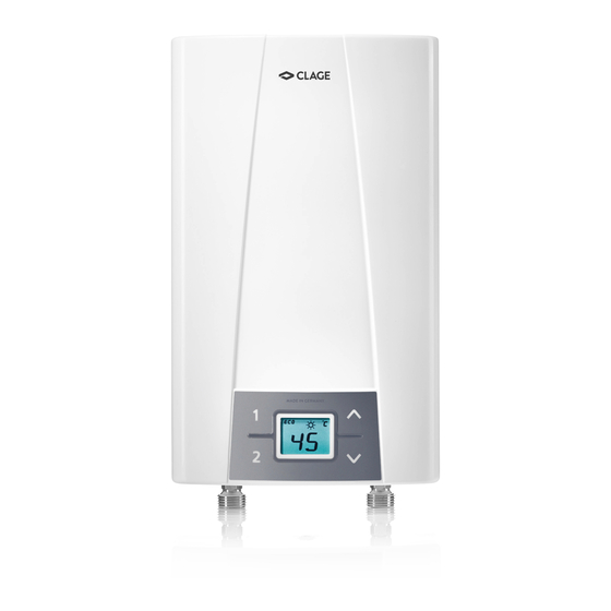
clage CEX 9-U ELECTRONIC MPS Installation Instructions Manual
Instantaneous water heater
Hide thumbs
Also See for CEX 9-U ELECTRONIC MPS:
- Installing instructions (56 pages) ,
- Operating instructions manual (56 pages)

Related Manuals for clage CEX 9-U ELECTRONIC MPS


Summary of Contents for clage CEX 9-U ELECTRONIC MPS
-
Page 1: Installation Instructions
Electronically controlled instantaneous water heater CEX 9-U: 27910 - 50 °C models Installation instructions For 50 ºC models, the appliance delivers water not exceeding 50 ºC in accordance with AS3498. -
Page 2: Overview
1. Overview When ordering spare parts, please always specify the appliance model and serial number. Pos. Part.-No. Description Pos. Part.-No. Description Grommet Cold and hot water connection 1/2“ Connecting terminal 801116 Temperature sensor set 801110 Flow sensor 801117 Heating element with STCO (STDB) 801101 Non-return valve Bottom part... -
Page 3: Table Of Contents
Contents 1. Overview ....................2 2. -
Page 4: Safety Instructions
3. Safety instructions Installation, initial operation and maintenance of this appliance must only be conducted by an authorised professional, who will then be responsible for adherence to applicable standards and installation regulations. We assume no liability for any damages caused by failure to observe these instructions. -
Page 5: Technical Specifications
4. Technical specifications ® Model CEX 9-U ELECTRONIC MPS 27910 Part no. Rated capacity / rated current 6,0 / 9,6 kW (27,3 / 40 A) Chosen capacity @ 230 V 6,6 kW (28,7 A) 8,8 kW (38,3 A) Electrical connection 1/N/PE 220..240 V AC... -
Page 6: Typical Installations
6. Typical installations Example of a closed-outlet installation:... - Page 7 6. Typical installations Example of a closed-outlet installation:...
-
Page 8: Installation
7. Installation The following regulations must be observed: • Installation must comply with all statutory regulations, AS/NZS 3000, AS/NZS 3500, as well as those of the local electricity and water supply companies. • The specifications on the rating plate. • Technical specifications. •... -
Page 9: Mounting The Appliance
7. Installation Mounting the appliance 1. Thoroughly rinse the water supply pipes before installation to remove soiling from the pipes. 2. Hold the appliance on the wall, and mark the drill lines at top and bottom, right and left, corresponding to the small notches at the edge of the appliance hood (see bottom figure). -
Page 10: Electrical Connection
8. Electrical connection • The electrical installation should comply with current regulations, AS/NZS 3000 and any Local Authority requirements. • The appliance must be installed according to the specifi cation on the rating plate and Fig.1 Wiring diagram the technical specifi cations. •... -
Page 11: Initial Operation
9. Initial operation Commissioning Before switching on the power supply, ensure the appliance is completely filled with water by carefully opening and closing the hot water tap until all air has been eliminated from the water heater and no more air emerges. Each time the appliance is drained (e.g. -
Page 12: Note "Reinstallation
9. Initial operation Note “Reinstallation“ If the appliance is to be re-commissioned under different installation conditions it may be necessary to alter the maximum power rating. This should only be done by a competent installer. To re-set the maximum power rating use a screwdriver to short circuit the two pins as shown in Fig.5. This will reset all heater parameters to factory settings. -
Page 13: Lock Level
9. Initial operation Lock level The operating mode of the appliance can be restricted. Refer to instructions under “Service Menu“ to set the lock level. This should only be done by a qualified tradesperson. Activation of the Lock level: 1. Set required lock level in the service menu. 2. -
Page 14: Service Menu
10. Service menu The service menu offers an overview of system parameters and is used for diagnostics. Press key and key simultaneously for at least 2 seconds to call up the Service-Menü ansehen Service menu service menu, the display confirms by “FL” and by a flashing point. Using the arrow keys , you can switch between the individual menus. - Page 15 10. Service menu Menu item order of “Service menu“: “3” same as “2” additionally nominal value memory 1 and 2 not changeable “4” same as “3”, additionally nominal value not changeable Note: When the setting “1“, “2“, “3“ or “4“ was chosen, the system parameters can no longer be modified in the service menu.
-
Page 16: Quick Reference Guide
Head Office Telephone: (02) 9796 3100 Free Call: 1 800 638 633 Zip Heaters (Aust) Pty. Ltd. ABN: 46 000 578 727 67 Allingham Street As Zip policy is one of continuous Condell Park NSW 2200 product improvement, changes Postal: Locked Bag 80 to specifications may be made Bankstown 1885 Australia without prior notice.
Need help?
Do you have a question about the CEX 9-U ELECTRONIC MPS and is the answer not in the manual?
Questions and answers