Dell PowerEdge T20 Owner's Manual
Hide thumbs
Also See for PowerEdge T20:
- Owner's manual (85 pages) ,
- Technical manual (29 pages) ,
- Getting started manual (7 pages)
Table of Contents
Advertisement
Quick Links
Advertisement
Table of Contents
Troubleshooting

Related Manuals for Dell PowerEdge T20


Summary of Contents for Dell PowerEdge T20
- Page 1 Dell PowerEdge T20 Owner's Manual Regulatory Model: D13M Regulatory Type: D13M001...
- Page 2 WARNING: A WARNING indicates a potential for property damage, personal injury, or death. Copyright © 2016 Dell Inc. All rights reserved. This product is protected by U.S. and international copyright and intellectual property laws. Dell and the Dell logo are trademarks of Dell Inc.
-
Page 3: Table Of Contents
Contents 1 About Your System....................7 ....................7 Front-Panel Features And Indicators .....................8 Back-Panel Features And Indicators ..........................9 NIC Indicator Codes ..................10 Power Indicator Codes For Power Supply ..................... 11 Complete The Operating System Setup .......................11 Other Information You May Need 2 Using The System Setup And Boot Manager.......... - Page 4 ......................31 Removing The Power Switch ......................32 Installing The Power Switch ..........................33 Input/Output Panel ....................33 Removing The Input/Output Panel ....................34 Installing The Input/Output Panel ............................34 Hard Drives ....................34 Removing The Hard-Drive Cage ....................35 Installing The Hard-Drive Cage ............
- Page 5 ............. 61 Entering The Service Tag After Replacing The System Board 4 Troubleshooting Your System................. 62 ....................62 Safety First—For You And Your System ........................62 Power LED Diagnostics ..........................63 Memory Beep Code .................... 63 Troubleshooting System Startup Failure ..................... 63 Troubleshooting External Connections .....................
- Page 6 ........................... 83 Contacting Dell ..................... 83 Locating Your System Service Tag ........................83 Documentation Feedback...
-
Page 7: About Your System
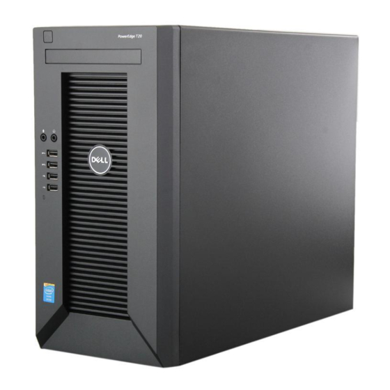
About Your System Front-Panel Features And Indicators Figure 1. Front-Panel Features and Indicators Item Indicator, Button, or Icon Description Connector Power-on indicator, The power-on indicator lights when the system power button power is on. The power button controls the power supply output to the system. -
Page 8: Back-Panel Features And Indicators
Item Indicator, Button, or Icon Description Connector Microphone connector Allows you to connect a microphone to the system. USB connectors (2) Allow you to connect USB devices to the system. The ports are USB 3.0 compliant. USB connectors (2) Allow you to connect USB devices to the system. The ports are USB 2.0 compliant. -
Page 9: Nic Indicator Codes
Item Indicator, Button, or Icon Description Connector Display ports (2) Allow you to connect other external display devices to the system. USB connectors (2) Allow you to connect USB devices to the system. The ports are USB 3.0 compliant. Video connector Allows you to connect a VGA display to the system. -
Page 10: Power Indicator Codes For Power Supply
Indicator Indicator Code Orange — a good 1000 Mbps connection exists between the network and the system. Off (no light) — the system is not detecting a physical connection to the network. Network activity Yellow light — A blinking yellow light indicates that network activity is present. light on integrated network adapter Power Indicator Codes For Power Supply... -
Page 11: Complete The Operating System Setup
• For latest information on supported operating systems, see dell.com/ossupport. NOTE: Always check for updates on dell.com/support/manuals and read the updates first because they often supersede information in other documents. NOTE: When upgrading your system, it is recommended that you download and install the latest... -
Page 12: Using The System Setup And Boot Manager
Using The System Setup And Boot Manager System Setup enables you to manage your system hardware and specify BIOS-level options. The following keystrokes provide access to system features during startup: Keystroke Description <F2> Enters the System Setup. <F12> Enters the Boot Manager. From the System Setup, you can: •... -
Page 13: Entering System Setup
NOTE: Operating systems must be UEFI-compatible to be installed from the UEFI boot mode. DOS and 32-bit operating systems do not support UEFI and can only be installed from the Legacy boot mode. NOTE: For the latest information on supported operating systems, go to dell.com/ossupport. Entering System Setup Turn on or restart your system. -
Page 14: Responding To Error Messages
Click Drivers & Downloads. On the Drivers and Downloads screen, under the Operating System drop-down list, select BIOS. 10. Identify the latest BIOS file and click Download File. 11. Select your preferred download method in the Please select your download method below window and click Download File. - Page 15 Option Description • UEFI NOTE: If you boot the system to the BIOS boot mode after installing an operating system with UEFI boot mode, the system does not respond. You must boot to the same boot mode in which you installed the operating system.
- Page 16 Option Description • Enable SMART Reporting — This option is disabled by default. USB Configuration This field configures the integrated USB controller. If Boot Support is enabled, the system is allowed to boot any type of USB mass storage devices (HDD, memory key, floppy). If the USB port is enabled, the device attached to this port is enabled and available for the operating system.
- Page 17 Option Description Internal HDD_0 Password This option lets you set, change, or delete the password on the system's internal hard disk drive. The Internal HDD_0 Password enables several security features. Enter the old password. Enter the new password. Confirm the new password. The drive does not have a password set by default.
- Page 18 Option Description • Deactivate — This option is disabled by default. • Disable • Activate Chassis-Intrusion Allows you to enable or disable the chassis-intrusion alert. • Disable • Enable • On-Silent — This option is enabled by default. Once a chassis intrusion has been detected, the system will add the chassis-intrusion alert into the BIOS events at each cold/warm boot.
- Page 19 Option Description • If you enable the Custom Mode, the relevant options for PK, KEK, db, and dbx are displayed. The options are: • Save to File — Saves the key to a user-selected file. • Replace from File — Replaces the current key with a key from a user- selected file.
- Page 20 Option Description • Power On • Last Power State Auto On Time This option sets the time of the day when you would like the system to turn on automatically. Time is kept in standard 12-hour format (hour:minutes:seconds). The startup time can be changed by typing the values in the time and A.M./P.M.
- Page 21 Table 7. POST Behavior Option Description Numlock LED Specifies if the NumLock function can be enabled when the system boots. This option is enabled by default. Keyboard Errors Specifies whether keyboard related errors are reported when it boots. This option is enabled by default. MEBx Hotkeys Specifies whether the MEBx Hotkey function should be enabled when the system boots.
-
Page 22: Boot Manager Screen
Enters System Setup. BIOS Flash Update Allows you to update the BIOS from the USB drive with the released BIOS file. This option is for advanced users. Download the BIOS file from dell.com/support. For more information, see Updating The BIOS. -
Page 23: System And Admin Password Features
NOTE: For most of the options, any changes that you make are recorded but do not take effect until you restart the system. System And Admin Password Features You can create a system password and a admin password to secure your system. To create a system and admin password, the password jumper must be set to enabled. -
Page 24: Deleting Or Changing An Existing System And Admin Password
Deleting Or Changing An Existing System And Admin Password Ensure that the Password Status is Unlocked (in the System Setup) before attempting to delete or change the existing System and/or admin password. You cannot delete or change an existing System or admin password, if the Password Status is Locked. -
Page 25: Installing System Components
Damage due to servicing that is not authorized by Dell is not covered by your warranty. Read and follow the safety instructions that came with the product. -
Page 26: Closing The System
Figure 5. Opening and Closing the System slots tabs system cover cover release latch Closing The System Ensure that all internal cables are connected and placed out of the way and that no tools or extra parts are left inside the system. Align the tabs on the system cover with the corresponding slots on the system chassis. -
Page 27: Installing The Bezel
Damage due to servicing that is not authorized by Dell is not covered by your warranty. Read and follow the safety instructions that came with the product. -
Page 28: Installing The Chassis-Intrusion Switch
Damage due to servicing that is not authorized by Dell is not covered by your warranty. Read and follow the safety instructions that came with the product. -
Page 29: Inside The System
Damage due to servicing that is not authorized by Dell is not covered by your warranty. Read and follow the safety instructions that came with the product. -
Page 30: Thermal Sensor
Damage due to servicing that is not authorized by Dell is not covered by your warranty. Read and follow the safety instructions that came with the product. -
Page 31: Power Switch
Damage due to servicing that is not authorized by Dell is not covered by your warranty. Read and follow the safety instructions that came with the product. -
Page 32: Installing The Power Switch
Damage due to servicing that is not authorized by Dell is not covered by your warranty. Read and follow the safety instructions that came with the product. -
Page 33: Input/Output Panel
Damage due to servicing that is not authorized by Dell is not covered by your warranty. Read and follow the safety instructions that came with the product. -
Page 34: Installing The Input/Output Panel
Damage due to servicing that is not authorized by Dell is not covered by your warranty. Read and follow the safety instructions that came with the product. -
Page 35: Installing The Hard-Drive Cage
Damage due to servicing that is not authorized by Dell is not covered by your warranty. Read and follow the safety instructions that came with the product. -
Page 36: Removing A 3.5 Inch Hard Drive From The Hard-Drive Cage
Damage due to servicing that is not authorized by Dell is not covered by your warranty. Read and follow the safety instructions that came with the product. -
Page 37: Removing A 2.5 Inch Hard Drive From The Hard-Drive Cage
Damage due to servicing that is not authorized by Dell is not covered by your warranty. Read and follow the safety instructions that came with the product. - Page 38 Figure 14. Removing and Installing the Hard-Drive Screws hard drive hard-drive screw sockets (4) hard-drive screw slots (2) hard-drive screws (4) Turn the hard-drive cage. Remove the screws on the sides of the hard-drive cage securing the hard drive to the hard-drive cage.
-
Page 39: Installing A 2.5 Inch Hard Drive In The Hard-Drive Cage
Damage due to servicing that is not authorized by Dell is not covered by your warranty. Read and follow the safety instructions that came with the product. -
Page 40: Removing A 3.5 Inch Hard Drive From The Hard-Drive Bay
Damage due to servicing that is not authorized by Dell is not covered by your warranty. Read and follow the safety instructions that came with the product. -
Page 41: Installing A 3.5 Inch Hard Drive In The Hard-Drive Bay
Damage due to servicing that is not authorized by Dell is not covered by your warranty. Read and follow the safety instructions that came with the product. -
Page 42: Installing A Hard Drive Into A Hard-Drive Carrier
Damage due to servicing that is not authorized by Dell is not covered by your warranty. Read and follow the safety instructions that came with the product. - Page 43 Figure 18. Removing and Installing the Optical-Drive Blank From the Bezel bezel retention clip optical-drive blank Remove the hard-drive cage. For information on removing the hard-drive cage, see Removing The Hard-Drive Cage. Hold the tabs on the optical-drive filler and remove the optical-drive filler from the hard-drive cage. Figure 19.
-
Page 44: Removing The Optical Drive
Damage due to servicing that is not authorized by Dell is not covered by your warranty. Read and follow the safety instructions that came with the product. -
Page 45: System Memory
For more information on removing the bezel, see Removing The Bezel. Remove the hard-drive cage. For more information on removing the hard-drive cage, see Removing The Hard-Drive Cage. Remove the screws securing the optical drive to the optical-drive/hard-drive slot. Slide the optical drive out of the optical-drive/hard-drive slot. Install the optical-drive filler into the optical-drive/hard-drive slot. -
Page 46: General Memory Module Installation Guidelines
Figure 21. Memory Socket Locations Memory channels are organized as follows: • channel A: memory sockets 1 and 3 • channel B: memory sockets 2 and 4 The following table shows the memory populations and operating frequencies for the supported configurations. -
Page 47: Sample Memory Configurations
Damage due to servicing that is not authorized by Dell is not covered by your warranty. Read and follow the safety instructions that came with the product. -
Page 48: Installing Memory Modules
Damage due to servicing that is not authorized by Dell is not covered by your warranty. Read and follow the safety instructions that came with the product. -
Page 49: System Fan
Damage due to servicing that is not authorized by Dell is not covered by your warranty. Read and follow the safety instructions that came with the product. -
Page 50: Installing The System Fan
Damage due to servicing that is not authorized by Dell is not covered by your warranty. Read and follow the safety instructions that came with the product. -
Page 51: Expansion Cards
Damage due to servicing that is not authorized by Dell is not covered by your warranty. Read and follow the safety instructions that came with the product. -
Page 52: Installing An Expansion Card
Damage due to servicing that is not authorized by Dell is not covered by your warranty. Read and follow the safety instructions that came with the product. -
Page 53: Processors
Damage due to servicing that is not authorized by Dell is not covered by your warranty. Read and follow the safety instructions that came with the product. - Page 54 Figure 25. Removing and Installing the Heat-Sink Assembly processor fan captive screws (4) processor fan cable heat sink screw sockets (4) CAUTION: The processor is held in its socket under strong pressure. Be aware that the release lever can spring up suddenly if not firmly grasped. Position your thumb firmly over the processor socket-release lever and release the lever from the locked position by pushing down and out from under the tab.
-
Page 55: Installing The Processor
Damage due to servicing that is not authorized by Dell is not covered by your warranty. Read and follow the safety instructions that came with the product. -
Page 56: Power Supply
Damage due to servicing that is not authorized by Dell is not covered by your warranty. Read and follow the safety instructions that came with the product. -
Page 57: Installing The Power Supply Unit
Damage due to servicing that is not authorized by Dell is not covered by your warranty. Read and follow the safety instructions that came with the product. -
Page 58: System Battery
Damage due to servicing that is not authorized by Dell is not covered by your warranty. Read and follow the safety instructions that came with the product. -
Page 59: System Board
Damage due to servicing that is not authorized by Dell is not covered by your warranty. Read and follow the safety instructions that came with the product. -
Page 60: Installing The System Board
Damage due to servicing that is not authorized by Dell is not covered by your warranty. Read and follow the safety instructions that came with the product. -
Page 61: Entering The Service Tag After Replacing The System Board
Entering The Service Tag After Replacing The System Board Enter the system service tag after you replace the system board. NOTE: To replace the system board within the warranty period, contact Dell for technical support. To replace the system board after the system warranty expires, see Removing The System Board. -
Page 62: Troubleshooting Your System
Damage due to servicing that is not authorized by Dell is not covered by your warranty. Read and follow the safety instructions that came with the product. -
Page 63: Memory Beep Code
Amber LED Description State memory modules are detected, but a memory failure possible peripheral card or system board failure possible USB failure no memory modules are detected possible system board error memory modules are detected, but a memory configuration or compatibility error possible system board resource and/or hardware failure some other failure with messages on screen Memory Beep Code... -
Page 64: Troubleshooting A Usb Device
Troubleshooting A USB Device Use the following steps to troubleshoot a USB keyboard/mouse. For other USB devices, go to step 7. Disconnect the keyboard and mouse cables from the system briefly and reconnect them. Connect the keyboard/mouse to the USB port(s) on the opposite side of the system. If the problem is resolved, restart the system, enter the System Setup, and check if the non- functioning USB ports are enabled. -
Page 65: Troubleshooting A Wet System
Damage due to servicing that is not authorized by Dell is not covered by your warranty. Read and follow the safety instructions that came with the product. -
Page 66: Troubleshooting The System Battery
Damage due to servicing that is not authorized by Dell is not covered by your warranty. Read and follow the safety instructions that came with the product. -
Page 67: Troubleshooting Cooling Problems
Damage due to servicing that is not authorized by Dell is not covered by your warranty. Read and follow the safety instructions that came with the product. -
Page 68: Troubleshooting An Optical Drive
Damage due to servicing that is not authorized by Dell is not covered by your warranty. Read and follow the safety instructions that came with the product. -
Page 69: Troubleshooting A Hard Drive
Damage due to servicing that is not authorized by Dell is not covered by your warranty. Read and follow the safety instructions that came with the product. -
Page 70: Troubleshooting The Processor
Damage due to servicing that is not authorized by Dell is not covered by your warranty. Read and follow the safety instructions that came with the product. -
Page 71: Using System Diagnostics
Using System Diagnostics If you experience a problem with your system, run the system diagnostics before contacting Dell for technical assistance. The purpose of running system diagnostics is to test your system hardware without requiring additional equipment or risking data loss. If you are unable to fix the problem yourself, service and support personnel can use the diagnostics results to help you solve the problem. - Page 72 Displays a time-stamped log of the results of all tests run on the system. This is displayed if at least one event description is recorded. For information about embedded system diagnostics, see the Dell Enhanced Pre-boot System Assessment User Guide at dell.com/support/manuals.
-
Page 73: Jumpers And Connectors
Jumpers And Connectors System Board Jumper Settings For information on resetting the password jumper to disable a password, see System Board Jumper Settings Table 14. System Board Jumper Settings Jumper Setting Description PSWD The password feature is enabled. (jumper engaged_ default) Clears BIOS password. -
Page 74: System Board Connectors
System Board Connectors Figure 30. System Board Jumpers and Connectors Item Connector Description FRONTPANEL Front IO connector PSWD Password jumper INT_USB Internal USB connector RTCRST RTCRST jumper INT_SPKR Internal speaker SLOT 4 PCIe card connector 4 SLOT 3 PCI card connector 3 SLOT 2 PCIe card connector 2 BATTERY... -
Page 75: Disabling A Forgotten Password
Item Connector Description DDR DIMM memory slots (4) DIMM slots 1–4 PWR_SW Power switch connector POWER P1 power connector SATA2 SATA2 connector SATA3 SATA3 connector HDD_ODD_POWER HDD_ODD power cable connector SATA0 SATA0 connector SATA1 SATA1 connector USB 3_FRONT Front USB 3.0 connector THRM Thermal sensor connector Disabling A Forgotten Password... -
Page 76: Technical Specifications
Technical Specifications Processor • One Intel Xeon processor E3-1225v3, or Processor type • One Intel Pentium processor G3220 Expansion Bus Bus type PCI Express Generation 2 and 3 Expansion slots (Slot 1) One full-height, half-length x16 PCIe Gen3 card slot connected to processor (Slot 2) One full-height, half-length x1 PCIe Gen2 card slot connected to Platform Controller Hub (PCH) -
Page 77: Environmental Specifications
Drives Up to four 3.5 inch internal, cabled SATA, or SATA SSD drives and one optical disk drive (optional). Two 3.5 inch and two 2.5 inch (optional), internal, cabled SATA, or SATA SSD drives. Six hard-drive systems Up to four 3.5 inch and two 2.5 inch (optional), internal, cabled SATA, or SATA SSD drives. - Page 78 Relative Humidity (maximum) Operating 20% to 80% (non-condensing) Storage 5% to 95% (non-condensing) Maximum Vibration Operating 0.26 G Storage 2.20 G Maximum Shock Operating 40 G Storage 105 G Altitude Operating –15.20 m to 3048 m (-50 ft to 10,000 ft) NOTE: In compliance with the requirements of the official Chinese standards, the operating altitude for systems shipping in...
-
Page 79: System Messages
The BIOS found a faulty disk sector or could not find a particular disk sector. found Alert! Previous The system failed to complete the boot routine three consecutive times for the attempts at same error. Contact Dell and report the checkpoint code (nnnn) to the support booting this technician. system have failed at checkpoint [nnnn]. - Page 80 Error Message Description Diskette read The floppy disk may be defective or a cable may be loose. If the drive access light failure turns on, try a different disk. Diskette subsystem The floppy drive controller may be faulty. reset failed Gate A20 failure One or more memory modules may be faulty or improperly seated.
- Page 81 Error Message Description value expecting value Memory odd/even A memory module may be faulty or improperly seated. Reinstall the memory logic failure at modules and, if necessary, replace them address, read value expecting value Memory write/read A memory module may be faulty or improperly seated. Reinstall the memory failure at address, modules and, if necessary, replace them.
-
Page 82: Warning Messages
The keyboard controller may be malfunctioning or a memory module may be interrupt in loose. protected mode WARNING: Dell's During initial startup, the drive detected possible error conditions. When your Disk Monitoring system finishes booting, immediately back up your data and replace your hard System has drive. -
Page 83: Getting Help
Dell to route support calls to the appropriate personnel. Documentation Feedback If you have feedback for this document, write to documentation_feedback@dell.com. Alternatively, you can click on the Feedback link in any of the Dell documentation pages, fill out the form, and click Submit to send your feedback.