Table of Contents
Advertisement
Advertisement
Table of Contents
Troubleshooting

Subscribe to Our Youtube Channel
Related Manuals for Endurance T50


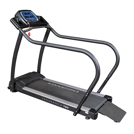
Summary of Contents for Endurance T50
- Page 1 091709 Endurance T50 Treadmill ® User Manual v. T50-040516...
-
Page 2: Table Of Contents
Table of Contents RefeRence DRawIngs......BefoRe You BegIn........III. IMPoRTanT safeTY InsTRucTIons..safeTY guIDelInes........6 – 8 asseMBlY InsTRucTIons......asseMBlY sTePs........10 – 19 VII. seTTIng uP YouR TReaDMIll....VIII. oPeRaTIng YouR TReaDMIll....21– 22 oPeRaTIng THe console......23– 25 eXeRcIse TIPs anD guIDelInes.... -
Page 3: Reference Drawings
Reference Drawings note: Due to continuing product improvements, specifications and designs are subject to change without notice. Even though we have prepared this manual with extreme care, neither the publisher nor the author can accept responsibility for any errors in, or omission from, the information given. -
Page 4: Before You Begin
Please take the time to carefully read through this manual thoroughly. Instructions contained in this document are not intended to cover all details or variations possible with Endurance Equipment, or to cover every contingency that may be met in conjunction with installation, operation, maintenance or troubleshooting of the equipment. -
Page 5: Important Safety Instructions
Locate the unit a few feet from the walls or furniture to provide easy access. The T50 is designed for your enjoyment. By following these precautions and using common sense, you will have many safe and pleasurable hours of healthful exercise with your Endurance T50. -
Page 6: Safety Guidelines
Safety Guidelines Successful cardio training programs have one prominent feature in common...safety. Cardio training has some inherent dangers, as do all physical activities. The chance of injury can be greatly reduced or completely removed by using correct running techniques, proper breathing, maintaining equipment in good working condition, and by wearing the appropriate clothing. -
Page 7: Grounding Instructions
rge protector, and plug the surge otector into an appropriate outlet Safety Guidelines at is properly installed and ounded in accordance with all local des and ordinances. Before beginning any exercise program, always consult with your physician. If you experience chest pains, nausea, dizziness or shortness of breath, stop exercising and consult your physician before continuing. -
Page 8: Mechanical Safety
Safety Guidelines This exercise equipment is designed and built for optimum safety for home use. However, certain precautions always apply whenever you operate any exercise equipment. Be sure to read the entire manual before assembly and operation of this machine. Also, please note the following safety precautions. -
Page 9: Assembly Instructions
Assembly Instructions Assembly of the T50 takes professional installers about 1/2 hour to complete. If this is the first time you have assembled this type of equipment, plan on significantly more time. professional installers are highly recommended! However, if you acquire the appropriate tools, obtain assistance, and follow the assembly steps sequentially, the process will take time, but is fairly easy. - Page 10 Step 1 Be careful to assemble all components in the sequence they are presented. Note: Do not fully tighten bolts until the unit is completely assembled. Position all the components from the box onto a clean area. NoTe: The following tools have been included to ease treadmill setup. Allen Wrench M6 x 70 Allen Wrench...
- Page 11 Step 1 Above shows STEP 1 assembled and completed.
- Page 12 Step 2 Be careful to assemble all components in the sequence they are presented. Note: Do not fully tighten bolts until the unit is completely assembled. Connect Cable A1 (88) to Cable A2 (89). Secure Right Upright Post (F) to Main Frame (A) by using: two 48 (m10x25 round allen head bolt) Four 65 (M10.5 flat washer) two 70 (m10 nut)
- Page 13 Step 2 Above shows STEP 2 assembled and completed.
- Page 14 Step 3 Be careful to assemble all components in the sequence they are presented. Note: Do not fully tighten bolts until the unit is completely assembled. Slide Handle Bar (K) into Right Upright Post (F) and secure using: two 59 (m5x10 phillips head bolt) two 67 (m5.5 arc washer) Slide the remaining Handle Bar (K) into Left Upright Post (G) and secure using:...
- Page 15 Step 3 Above shows STEP 3 assembled and completed.
- Page 16 Step 4 Be careful to assemble all components in the sequence they are presented. Note: Do not fully tighten bolts until the unit is completely assembled. Bring Console (93) near Right Upright Post (F) and Left Upright Post (G) for installation.
- Page 17 Step 4 Above shows STEP 4 assembled and completed.
- Page 18 Start with 0.1 mph workouts and slowly increase the treadmill speed as you become more familiar with the treadmill and the physical endurance is appropriate. Remember, before beginning any fitness program, you should obtain a complete physical examination and workout instructions from your physician.
- Page 19 Step 5 Above shows STEP 5 assembled and completed.
-
Page 20: Setting Up Your Treadmill
Setting up your Treadmill pLacement in YOUR hOme To make exercise a desirable daily activity for you, the treadmill should be placed in a comfortable and attractive setting. This treadmill is designed to use minimal floor space and to fit nicely in your home. Do not place or operate the treadmill outdoors. -
Page 21: Operating Your Treadmill
Operating your Treadmill tURn pOWeR On The On/Off switch for the treadmill is located next to the power supply cord receptacle on the front of the treadmill. Insert the power supply cord into the receptacle and flip the switch to the “ON”... -
Page 22: Getting On And Off The Treadmill
Operating your Treadmill SaFetY keY anD cLip The safety key is designed to cut the main power to the treadmill should you fall. Therefore, the safety key is intended to bring the treadmill to an immediate stop. At high speeds, it may be uncomfortable and somewhat dangerous to come to a complete stop immediately. -
Page 23: Operating The Console
Operating the Console funCtion Keys time & DiStance Displays Time or Distance every 6 seconds. pULSe & caLORie SpeeD Monitors Pulse or Calorie Treadmill speed is readings every 6 seconds. displayed in this window SaFetY keY SpeeD Used for emergency stopping StaRt/ Increase or only. - Page 24 SLeep mODe sleeP MoDe allows the treadmill to conserve energy by entering into low power mode. The T50 treadmill will go into SLEEP MODE when operation has ceased for 10 minutes. Press any button to reactivate the treadmill. DiSpLaY VaLUeS The Console’s display is set to readout according to the values below.
-
Page 25: Quick Start
Once power is turned on and the safety key is secured in place, all console values will display zero. Simply press the button. After a 5 second countdown, the T50 treadmill will start. Press the SPEED button to the desired workout speed once the treadmill has started. -
Page 26: Exercise Tips And Guidelines
The T50 has also been designed for users in need of strength and aerobic conditioning. With a low profile step-up height, easy-to-read... - Page 27 Excercise Tips and Guidelines There are two ways to measure your exercise intensity. The first is by evaluating your perceived exertion level and the second is by monitoring your heart rate. During exercise, if you cannot maintain a conversation without gasping, you are working too hard. A good rule of thumb is to work to the point of exhilaration, not exhaustion.
-
Page 28: Maintenance
Maintenance To reduce the risk of electrical shock, always unplug the treadmill from the electrical outlet immediately after use and before maintenance! cLeaning Remove dust on the treadmill with a vacuum or a slightly damp cloth. Folding up the deck and cleaning the floor with a vacuum periodically will help prolong the treadmill product life. - Page 29 Maintenance To reduce the risk of electrical shock, always unplug the treadmill from the electrical outlet immediately after use and before maintenance! RUnning BeLt centeRing pROceDURe: 1. Do not wear loose clothing, neckties, or loose jewelry while making this adjustment. 2.
- Page 30 Maintenance To reduce the risk of electrical shock, always unplug the treadmill from the electrical outlet immediately after use and before maintenance! DRiVe BeLt tenSiOning Sometimes, after extended use, adjustment of the drive belt may be necessary. To tighten the drive belt, turn the adjustment bolts clockwise. Motor Belt adjustment method: Loosen M8 Nuts (71) by turning them counterclockwise.
-
Page 31: Lubricating The Deck
Maintenance A well lubricated deck will ensure longevity of your treadmill in addition to providing you optimal performance. LUBRicating the Deck A well lubricated deck will ensure high performance of your treadmill and reduce the level of normal wear and tear to important components. This treadmill has been pre-lubed at the factory. -
Page 32: Troubleshooting
Please use this Owner’s Manual to make sure that all parts have been included in your ship- ment. When ordering parts, you must use the part number and description from this Owner’s Manual. Use only Endurance replacement parts when servicing this machine. Failure to do so will void your warranty and could result in personal injury. -
Page 33: Error Codes
A list of error codes are shown below in the case such an event were to occur. If you experience an error code with your treadmill, please unplug your treadmill and contact your authorized Endurance dealer or a Endurance factory-authorized service company or contact Endurance customer service. -
Page 34: Troubleshooting Guide
Troubleshooting Guide problem potential cause correction 1. Plug into grounded 1. Not plugged in. outlet. 2. Insert safety key into 2. Safety key not inserted. console. Treadmill Will Not Start. 3. House circuit breaker 3. Reset or replace fuse. tripped. 4. -
Page 35: Hardware
Hardware (112) Allen Head Bolt M8x45 Qty. 1 (70) Nut M10 Qty. 6 (55) Allen Head Bolt M8x30 Qty. 4 (71) Nut M8 Qty. 4 (48) Allen Head Bolt M10x25 Qty. 8 (65) Flat Washer M10.5 Qty. 14 (51) Allen Head Bolt M8x15 Qty. 1 (66) Flat Washer M8.5 Qty. - Page 36 Assembly Hardware List (Steps 1 - 5) Part# DesCriPtion Main Frame Upright Post (R) Upright Post (L) Vertical Bar Lower Handle Bar Handle Bar Lower Cable Lower Cable Shroud Cable Upright Post (R) Cable Shroud Cable Upright Post (R) Cable Shroud Cable Upright Post (L) Cable Part#...
-
Page 37: Hardware List
Complete Hardware List Part# DesCriPtion Main Frame Undercarriage Plate Motor Compartment Plate Ramp Ramp Support Bracket Upright Post (R) Upright Post (L) Vertical Bar Lower Handle Bar Handle Bar Rear Roller Assembly Front Roller Assembly Motor Cover Bracket (R) Motor Cover Bracket (L) Support Tube Lower Cable Lower Cable... - Page 38 Complete Hardware List Part# DesCriPtion Dimension Moving Wheel Side Rail Twin Double Sided Tape t3.0 x 25 x 580mm Side Foot Platform (L) Side Foot Platform (R) Running Deck Running Belt Heart Rate Housing Dc Motor Motor Control Board Transformer speed sensor Ramp Foam Pad t6.0 x 15 x 110mm...
- Page 39 Complete Hardware List Part# DesCriPtion Dimension 1/2” x 13mm Phillips Head Screw M3x10 Phillips Head Screw M4x8 Spring Washer M4.5 Flat Washer M4.5 Allen Head Bolt M8x45 End Cap M13x26 End Cap M15x30 Side Sticker (L) Side Sticker (R) Motor Cover Sticker connection wire 120mm connection wire...
-
Page 40: Wiring Diagram
T50 Wiring Diagram... -
Page 41: Notes
Notes... -
Page 42: Exploded View Diagram
Exploded View Diagram... - Page 43 Exploded View Diagram...
- Page 44 Serial Number is Located on the Frame Model Name Purchase Date : _______________________________ Serial Number : 007734-_______________________ Customer Tech Support Hotline Toll Free: 1-800-556-3113 Phone: 1-708-427-3555 Fax: 1-708-427-3556 Hours: M-F 8:30-5:00 CST E-Mail: service@bodysolid.com Copyright 2009. Body-Solid. All rights reserved. Body-Solid reserves the right to change design and specifications when we feel it will improve the product. Body-Solid machines maintain several patented and patent pending features and designs.
Need help?
Do you have a question about the T50 and is the answer not in the manual?
Questions and answers