Table of Contents
Advertisement
Advertisement
Table of Contents

Related Manuals for thomann The t.bone


Summary of Contents for thomann The t.bone
- Page 1 free solo PT UHF wireless system user manual...
- Page 2 Musikhaus Thomann Thomann GmbH Hans-Thomann-Straße 1 96138 Burgebrach Germany Telephone: +49 (0) 9546 9223-0 E-mail: info@thomann.de Internet: www.thomann.de 17.11.2015, ID: 296201, 296203, 296204, 296206, 323196 (V2)
-
Page 3: Table Of Contents
Table of contents Table of contents General information..........................5 1.1 Further information........................... 6 1.2 Notational conventions........................7 1.3 Symbols and signal words....................... 8 Safety instructions............................. 9 Features............................... 13 Installation and operation........................15 4.1 General Information........................15 4.2 Receiver............................... 16 4.3 Transmitter............................18 Connections and controls........................ - Page 4 Table of contents 6.2 Transmitter............................36 Technical specifications........................39 7.1 Transmitter............................39 7.2 Receiver............................... 42 Plug and connection assignment....................43 Troubleshooting............................46 Protecting the environment......................49 UHF wireless system...
-
Page 5: General Information
General information General information This manual contains important instructions for the safe operation of the unit. Read and follow the safety instructions and all other instructions. Keep the manual for future reference. Make sure that it is available to all those using the device. If you sell the unit please make sure that the buyer also receives this manual. -
Page 6: Further Information
General information 1.1 Further information On our website (www.thomann.de) you will find lots of further information and details on the following points: Download This manual is also available as PDF file for you to download. Use the search function in the electronic version to find the topics of Keyword search interest for you quickly. -
Page 7: Notational Conventions
General information 1.2 Notational conventions This manual uses the following notational conventions: Letterings The letterings for connectors and controls are marked by square brackets and italics. Examples: [VOLUME] control, [Mono] button. Instructions The individual steps of an instruction are numbered consecutively. The result of a step is indented and highlighted by an arrow. -
Page 8: Symbols And Signal Words
General information 1.3 Symbols and signal words In this section you will find an overview of the meaning of symbols and signal words that are used in this manual. Signal word Meaning DANGER! This combination of symbol and signal word indicates an immediate dangerous situation that will result in death or serious injury if it is not avoided. -
Page 9: Safety Instructions
Safety instructions Safety instructions Intended use This device is intended to be used for the wireless transmission of audio signals from micro‐ phones or instruments to amplifiers or active speakers. Use the device only as described in this user manual. Any other use or use under other operating conditions is considered to be improper and may result in personal injury or property damage. - Page 10 Safety instructions Safety DANGER! Danger for children Ensure that plastic bags, packaging, etc. are disposed of properly and are not within reach of babies and young children. Choking hazard! Ensure that children do not detach any small parts (e.g. knobs or the like) from the unit.
- Page 11 Safety instructions NOTICE! External power supply The device is powered by an external power supply. Before connecting the external power supply, ensure that the input voltage (AC outlet) matches the voltage rating of the device and that the AC outlet is protected by a residual cur‐ rent circuit breaker.
- Page 12 Safety instructions NOTICE! Possible damage by leaking batteries Leaking batteries can cause permanent damage to the device. Take batteries out of the device if it is not going to be used for a longer period. UHF wireless system...
-
Page 13: Features
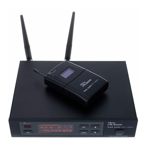
Features Features The UHF Wireless System is especially suited for professional audio transmission, for example at events, on rock stages and concert podiums, in theatres, musicals and discos. Your UHF Wireless System free solo PT is comprised of the following components: 9.5"... - Page 14 Number of available quency groups channels the t.bone free solo PT 600 MHz (item no. 296201) the t.bone free solo PT 740 MHz (item no. 296203) the t.bone free solo PT 823 MHz (item no. 296204) the t.bone free solo PT 863 MHz (item no. 296206) the t.bone free solo PT 1.8 GHz (item no.
-
Page 15: Installation And Operation
Installation and operation Installation and operation 4.1 General Information Unpack and carefully check that there is no transportation damage before using the unit. Keep the equipment packaging. To fully protect the device against vibration, dust and moisture during transportation or storage use the original packaging or your own packaging material suitable for transport or storage, respectively. -
Page 16: Receiver
For more information, please visit: http://www.thomann.de. Make sure that transmitter and receiver are both tuned to the same channel. - Page 17 Installation and operation Connecting the power supply NOTICE! External power supply The device is powered by an external power supply. Before connecting the external power supply, ensure that the input voltage (AC outlet) matches the voltage rating of the device and that the AC outlet is protected by a residual cur‐ rent circuit breaker.
-
Page 18: Transmitter
Installation and operation Attaching the antennas Attach the included antennas to the rear panel of the transmitter. To improve the transmission quality and to adapt to the spatial conditions they are rotatable and swivelling. In case the space provided on the device for direct assembly of the antennas is not sufficient, for example because the space on the rack is narrow, you can use the optionally available coaxial cable to assemble the antennas separately from the device. - Page 19 Installation and operation Connecting the microphone or Ensure that the transmitter is switched off. instrument to the transmitter Connect the microphone or instrument cable to the input on the transmitter (mini-XLR panel connector). Turn on the transmitter and check the transmission by using the microphone or instru‐ ment.
-
Page 20: Connections And Controls
Connections and controls Connections and controls 5.1 Receiver Front panel UHF wireless system... - Page 21 Connections and controls 1 [POWER] Press the switch for several seconds to switch the device on or off. Press the switch once briefly to mute the device. All previous settings are retained even when you switch the device off and disconnect it from the mains. 2 Infra red receiver.
- Page 22 Connections and controls 8 [AUTO] Starts an automatic search to find a free channel. 12, 13 Suitable UHF antennas. The receiver evaluates the radio signal from both antennas and selects the signal with the higher quality for further processing. UHF wireless system...
- Page 23 Connections and controls Rear panel free solo PT...
- Page 24 Connections and controls 9 [DC 12-18V] Socket for connecting the supplied AC power supply. If you are using a different power supply, observe the correct voltage, the polarity of the plug and the power consumption. 10 [BALANCED OUTPUT] Male XLR panel connector as symmetrical audio signal output for direct connection with a mixer, a power amplifier, or a recording device.
- Page 25 Connections and controls Display free solo PT...
- Page 26 Connections and controls 15 [GP] Indicates the selected frequency group. 16 [CH] Indicates the selected channel. Indicates that the unit is locked to prevent unintentional operation. Shows that the receiver has been muted. 19 [A/B] Shows which of the two antennas is currently being used for signal transmission. 20 [SQ] Shows the set squelch level for the radio signal.
- Page 27 Connections and controls 22 Shows the battery status of the transmitter from which the device just received a signal. 23 [AUTO] Shows that an automatic search is running to find a free channel. 24 [IR] Shows that an infra red signal is being received 25 [FREQUENCY] Indicates the frequency that is assigned to the set combination of frequency group and channel.
-
Page 28: Transmitter
Connections and controls 5.2 Transmitter Front panel UHF wireless system... - Page 29 Connections and controls 31 Display. 32 Antenna. 33 [MUTE] Shows that the device has been muted. 34 [BATT LOW] / [ON] Blinks when the battery is too low. 35 [SET] Opens the menu. keys Increase or decrease the value currently displayed. 37 Battery holder for two round cell batteries (AA, LR06), 1.5 V or comparable rechargeable batteries.
- Page 30 Connections and controls 39 INPUT Mini-XLR panel connector for connecting a microphone or instrument. 40 Main switch Press the switch for several seconds to switch the device on or off. Press the switch once briefly to mute the input. When the transmitter is muted, the symbol does not appear on the receiver display.
- Page 31 Connections and controls 51 [FREQUENCY] / [GP] / [CH] Depending on selected menu item: Indicates the frequency that is assigned to the set combination of frequency group and channel. Displays the set frequency group and the set channel. Indicates that the unit is locked to prevent unintentional operation. 53 [GAIN] Shows the level of the radio signal sent.
- Page 32 Connections and controls Shows that the transmitter has been muted. This is the case if the transmitter and receiver are working on different frequencies, if the receiver is not getting a usable signal or if you have muted the transmitter by briefly pressing the main switch. 56 Shows the output power.
-
Page 33: Instructions For Use
Instructions for use Instructions for use 6.1 Receiver Selecting frequency Press [SET]. ð The [GP] display blinks. Use the arrow keys to select the frequency group. Press [SET] to confirm the selection. ð The [CH] display blinks. Use the arrow keys to select a channel within the set frequency group. If you have selected frequency group ‘U’... - Page 34 Instructions for use Synchronizing transmitter and receiver Open the transmitter to expose the infra red sensor. Press [ADL]. The [IR] display blinks. Hold the infra red sensor of the transmitter near the infra red interface of the receiver for ten seconds. When synchronization has been successfully completed, the [IR] display stops blinking.
- Page 35 Instructions for use Automatic search for a free channel Press [AUTO]. ð The [AUTO] display blinks; the display shows the number of free channels available. Use the arrow keys to select one of the free channels. Press [SET] to confirm the selection. ð...
-
Page 36: Transmitter
Instructions for use 6.2 Transmitter The keys for operating the device are located under the flap on the front side. Select frequency If you don't wish to synchronize the transmitter with the receiver using the infra red interface, you can set the transmitting frequency manually in the configurable frequency group (user bank). - Page 37 Instructions for use Setting gain Keep pressing [SET] until the number in the [GAIN] field blinks on the display. Use the arrow keys to change the transmitter gain in increments of 3 dB (–3 dB, 0 dB, 3 dB, 6 dB, 9 dB). Press [SET] to confirm the selection.
- Page 38 Instructions for use Displaying frequency group and channel Press . ð The display shows the frequency group and channel being used. Press [SET] or wait five seconds to return to normal state. Locking the keypad Hold down until the symbol appears. ð...
-
Page 39: Technical Specifications
UHF band (600 MHz…1.8 GHz) Frequency band the t.bone free solo PT 600 MHz (item no. 296201): 596 MHz…620 MHz the t.bone free solo PT 740 MHz (item no. 296203): 740 MHz…752 MHz the t.bone free solo PT 823 MHz (item no. 296204): 823 MHz…832 MHz the t.bone free solo PT 863 MHz (item no. - Page 40 Technical specifications the t.bone free solo PT 1.8 GHz (item no. 323196): 15 MHz Number of channels the t.bone free solo PT 600 MHz (item no. 296201): 211 the t.bone free solo PT 740 MHz (item no. 296203): 37 the t.bone free solo PT 823 MHz (item no. 296204): 65 the t.bone free solo PT 863 MHz (item no.
- Page 41 Technical specifications Peak deviation ± 55 kHz NF frequency response 60 Hz…18 kHz < 0.5 % Signal-to-noise ratio > 102 dB (A) Operating supply voltage 2 AA cells (LR06, 1.5 V) or equivalent rechargeable batteries Battery life span > 8 h (with alkaline cells) Dimensions (W ×...
-
Page 42: Receiver
Technical specifications 7.2 Receiver Outputs XLR chassis plug, balanced 1/4" phone socket, unbalanced Sensitivity –102 dBm NF frequency response 50 Hz…15 kHz (±3 dB) < 0.8 % Signal-to-noise ratio > 105 dB (A) Operating supply voltage DC 12 V Dimensions (W × D × H, without antennas) 212 mm ×... -
Page 43: Plug And Connection Assignment
Plug and connection assignment Plug and connection assignment Introduction This chapter will help you select the right cables and plugs to connect your valuable equip‐ ment in such a way that a perfect sound experience is ensured. Please note these advices, because especially in ‘Sound & Light’ caution is indicated: Even if a plug fits into the socket, an incorrect connection may result in a destroyed power amp, a short circuit or ‘just’... - Page 44 Plug and connection assignment Since the interference affects both cores equally, by subtracting the phase-shifted signals, the interfering signal is completely neutralized. The result is a pure signal without any noise inter‐ ference. 1/4" TS phone plug (mono, unbalanced) Signal Ground, shielding 1/4"...
- Page 45 Plug and connection assignment XLR plug (balanced) Ground, shielding Signal (in phase, +) Signal (out of phase, –) Mini-XLR connections for signal A mini-XLR panel connector serves as a signal input on the transmitter. The figure and the input on the transmitter table show the mini-XLR pin assignment.
-
Page 46: Troubleshooting
Troubleshooting Troubleshooting In the following we list a few common problems that may occur during operation. We give you some suggestions for easy troubleshooting: UHF wireless system... - Page 47 Troubleshooting Symptom Remedy No sound 1. Check the power supply of the transmitter and receiver. 2. Make sure that both transmitter and receiver operate in the same frequency range. The frequency range is stated on the devices. 3. Are both transmitter and receiver set to the same channel? 4.
- Page 48 Troubleshooting If the procedures recommended above do not succeed, please contact our Service Center. You can find the contact information at www.thomann.de. UHF wireless system...
-
Page 49: Protecting The Environment
Protecting the environment Protecting the environment Disposal of the packaging mate‐ rial For the transport and protective packaging, environmentally friendly materials have been chosen that can be supplied to normal recycling. Ensure that plastic bags, packaging, etc. are properly disposed of. Do not just dispose these materials with your normal household waste, but make sure that they are fed to a recovery. - Page 50 Protecting the environment Disposal of your old device This product is subject to the European Waste Electrical and Electronic Equipment Directive (WEEE). Do not dispose with your normal household waste. Dispose this device through an approved waste disposal firm or through your local waste facility.
- Page 52 Musikhaus Thomann · Hans-Thomann-Straße 1 · 96138 Burgebrach · Germany · www.thomann.de...
Need help?
Do you have a question about the The t.bone and is the answer not in the manual?
Questions and answers