thomann t.bone free solo HT 600 MHz User Manual
Uhf wireless system
Hide thumbs
Also See for t.bone free solo HT 600 MHz:
- User manual (44 pages) ,
- User manual (56 pages) ,
- User manual (52 pages)
Table of Contents
Advertisement
Quick Links
Advertisement
Table of Contents

Related Manuals for thomann t.bone free solo HT 600 MHz


Summary of Contents for thomann t.bone free solo HT 600 MHz
- Page 1 free solo HT UHF wireless system user manual...
- Page 2 Musikhaus Thomann e.K. Treppendorf 30 96138 Burgebrach Germany Telephone: +49 (0) 9546 9223-0 E-mail: info@thomann.de Internet: www.thomann.de 28.11.2013...
-
Page 3: Table Of Contents
Table of contents Table of contents General notes............................... 5 Safety instructions............................. 7 Features............................... 11 Installation and starting up........................ 13 4.1 General information........................13 4.2 Receiver............................... 15 4.3 Transmitter............................18 Connections and operating elements................... 19 5.1 Receiver............................... 19 5.2 Transmitter............................27 Operating.............................. - Page 4 Table of contents Technical specifications........................42 8.1 Transmitter............................42 8.2 Receiver............................... 45 Protecting the environment......................46 UHF wireless system...
-
Page 5: General Notes
General notes General notes This user manual contains important information on safe operation of the device. Read and follow all safety notes and all instructions. Save this manual for future reference. Make sure that it is available to all persons using this device. If you sell the device, include the manual for the next owner. - Page 6 General notes Signal word Meaning DANGER! This combination of symbol and signal word indicates an immediate dangerous situation that will result in death or serious injury if it is not avoided. NOTICE! This combination of symbol and signal word indicates a possible dangerous situation that can result in material and environmental damage if it is not avoided.
-
Page 7: Safety Instructions
Safety instructions Safety instructions Intended use This device is intended to be used for the wireless transmission of audio signals from micro‐ phones or instruments to amplifiers or active speakers. Use the device only as described in this user manual. Any other use or use under other operating conditions is considered to be improper and may result in personal injury or property damage. - Page 8 Safety instructions Safety DANGER! Danger for children Ensure that plastic bags, packaging, etc. are disposed of properly and are not within reach of babies and young children. Choking hazard! Ensure that children do not detach any small parts (e.g. knobs or the like) from the unit.
- Page 9 Safety instructions NOTICE! External power supply The device is powered by an external power supply. Before connecting the external power supply, ensure that the input voltage (AC outlet) matches the voltage rating of the device and that the AC outlet is protected by a residual cur‐ rent circuit breaker.
- Page 10 Safety instructions NOTICE! Possible damage by leaking batteries Leaking batteries can cause permanent damage to the device. Take batteries out of the device if it is not going to be used for a longer period. UHF wireless system...
-
Page 11: Features
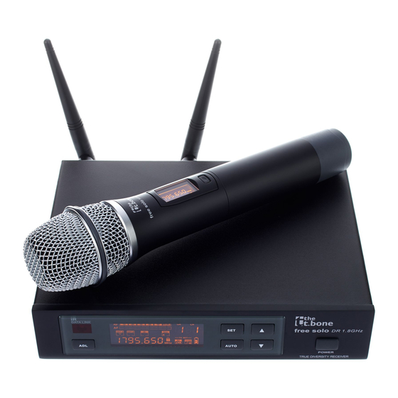
Features Features The UHF Wireless System is especially suited for professional audio transmission, for example at events, on rock stages and concert podiums, in theatres, musicals and discos. Your UHF Wireless System free solo HT is comprised of the following components: 9.5"... - Page 12 Number of available quency groups channels the t.bone free solo HT 600 MHz (item no. 296161) the t.bone free solo HT 740 MHz (item no. 296199) the t.bone free solo HT 823 MHz (item no. 296196) the t.bone free solo HT 863 MHz (item no. 296197) the t.bone free solo HT 1.8 GHz (item no.
-
Page 13: Installation And Starting Up
Installation and starting up Installation and starting up 4.1 General information Unpack and carefully check that there is no transportation damage before using the unit. Keep the equipment packaging. To fully protect the device against vibration, dust and moisture during transportation or storage use the original packaging or your own packaging material suitable for transport or storage, respectively. - Page 14 Installation and starting up Notes on wireless transmission This device utilizes frequencies that are not harmonized within the European Union (EU) and therefore may only be used in certain EU member states. In all European countries, the frequencies used for the transmission of audio signals are strictly regulated. Before you start, make sure the frequencies are allowed in the respective country and check whether the operation must be reported to the appropriate authority.
-
Page 15: Receiver
Installation and starting up 4.2 Receiver XLR connection for signal output on the receiver An XLR chassis socket serves as signal output on the receiver. Drawing and table indicate the XLR pin assignment (balanced wiring). Ground, shielding Positive signal (+) Negative signal (–) free solo HT... - Page 16 Installation and starting up Phone plug for signal output on the receiver A 1/4" phone socket (TS) serves as signal output on the receiver. Drawing and table indicate the pin assignment of a suitable plug. Signal Ground, shielding Rack mounting The device is 19"...
- Page 17 Installation and starting up Connecting the power supply NOTICE! External power supply The device is powered by an external power supply. Before connecting the external power supply, ensure that the input voltage (AC outlet) matches the voltage rating of the device and that the AC outlet is protected by a residual cur‐ rent circuit breaker.
-
Page 18: Transmitter
Installation and starting up Mounting antennas Attach the supplied antennas to the rear panel of the receiver. To improve transmission quality and to adapt to the spatial conditions the antennas are rotatable and swivelling. If the space for the direct mounting of the antennas on the unit is not sufficient, for example, because of restricted space in the rack, you can use the optional coaxial cable to mount the antennas separated from the unit. -
Page 19: Connections And Operating Elements
Connections and operating elements Connections and operating elements 5.1 Receiver Front panel free solo HT... - Page 20 Connections and operating elements 1 POWER Press the button for several seconds to turn the unit on or off. All previous settings are saved even if you turn off the power and disconnect the unit from the mains. 2 Infrared sensor. 3 [ADS] button Starts the synchronization of the settings with the transmitter.
- Page 21 Connections and operating elements 8 [AUTO] button Starts the automatic search for a free channel. 12, 13 Calibrated UHF antennas. The receiver evaluates the radio signal received by both antennas and selects the signal with the higher quality for further processing. free solo HT...
- Page 22 Connections and operating elements Rear panel UHF wireless system...
- Page 23 Connections and operating elements 9 DC 12-18V Socket to connect the supplied mains adapter. If you use a different power supply, observe the correct voltage, the polarity of the plug and the power consumption. 10 BALANCED OUTPUT XLR chassis connector as balanced audio signal output for direct connection to a mixer, a power amplifier or recording device.
- Page 24 Connections and operating elements Display UHF wireless system...
- Page 25 Connections and operating elements 15 GP Indicates the selected frequency group. 16 CH Indicates the selected channel. Indicates that the unit is locked to prevent unintentional operation. Indicates that the unit is muted. 19 A/B Indicates which of both antennas is currently used for signal transmission. 20 SQ Displays the adjusted level of the squelch for the radio signal.
- Page 26 Connections and operating elements 22 Shows the battery status of the transmitter from which the device is currently receiving a signal. 23 AUTO Indicates that the automatic search for a free channel is running. 24 IR Indicates that an IR signal is received. 25 FREQUENCY Indication of the frequency that is assigned to the set combination of frequency group and channel.
-
Page 27: Transmitter
Connections and operating elements 5.2 Transmitter free solo HT... - Page 28 Connections and operating elements 31 Display. 32 Microphone grille to prevent damage and to reduce wind and breath noise. 33 Main switch Press the button for several seconds to turn the unit on or off. Briefly press the button to mute or unmute the micro‐ phone.
- Page 29 Connections and operating elements 51 FREQUENCY / GP / CH Depending on the selected menu item: Indication of the frequency that is assigned to the set combination of fre‐ quency group and channel. Indication of the set frequency group and the selected channel. Indicates that the unit is locked to prevent unintentional operation.
- Page 30 Connections and operating elements Indicates that the transmitter is muted. This is the case when transmitter and receiver operate on different frequencies, if the receiver does not receive a usable signal or if you have muted the transmitter by briefly pressing the main switch. 56 Indicates the output power.
-
Page 31: Operating
Operating Operating 6.1 Receiver Selecting the frequency Press [SET]. ð The GP display is flashing. Use the arrow keys to select the frequency group. Press [SET] to confirm the selection. ð The CH display is flashing. Use the arrow keys to select a channel within the selected frequency group. If you have selected the frequency group ‘U’... - Page 32 Operating ð The display indicates that the receiver is being calibrated to a new frequency. After a few seconds the display will return to the default state. Synchronising transmitter and receiver Open the transmitter to uncover the infrared sensor. Press [ADS]. The IR display is flashing. Within ten seconds, hold the infrared sensor of the transmitter close to the infrared inter‐...
- Page 33 Operating Setting the squelch Press [SET] as long until the SQ area is flashing in the display. Use the arrow keys to set the desired value. The current value is shown on the right side of the display. Press [SET] to confirm the selection. ð...
-
Page 34: Transmitter
Operating Turning key lock on or off Press [SET] as long until the symbol appears. ð All buttons are locked except the main switch. To turn the key lock off, press as long until the symbol disappears. ð The buttons have regained their original function. 6.2 Transmitter Unscrew the bottom housing part to get access to the operating buttons. - Page 35 Operating Frequency selecting If you don't want to synchronise the transmitter via the infrared interface with the receiver, you can also set the transmission frequency manually in the configurable frequency group (user bank). Press [SET] repeatedly until the value in the GP field of the display is flashing. Use [SEL] to select the frequency group.
- Page 36 Operating Setting transmission gain Press [SET] repeatedly until the figure in the GAIN field is flashing. Use [SEL] to adjust the transmission gain in increments of 3 dB (–9 dB, –6 dB, –3 dB, 0 dB, 3 dB). Press [SET] to confirm the selection. Press the main switch to exit the menu without any changes.
- Page 37 Operating Frequency group and channel display Press [SEL]. ð The display indicates the used frequency group und the used channel. Press [SEL] or wait for five seconds to return to the default condition. Turning key lock on Press [SEL] as long until the symbol appears. ð...
- Page 38 Operating Turning key lock off To turn the key lock off press [SEL] and then [SET]. ð The symbol is flashing. Press [SEL] again and then [SET]. Press [SEL] a third time and then [SET]. ð The symbol disappears. The buttons have regained their original function. UHF wireless system...
-
Page 39: Troubleshooting
Troubleshooting Troubleshooting In the following we list a few common problems that may occur during operation. We give you some suggestions for easy troubleshooting: free solo HT... - Page 40 Troubleshooting Symptom Remedy No sound 1. Check the power supply of the transmitter and receiver. 2. Make sure that both transmitter and receiver operate in the same frequency range. The frequency range is stated on the devices. 3. Are both transmitter and receiver set to the same channel? 4.
- Page 41 Troubleshooting If the procedures recommended above do not succeed, please contact our Service Center. You can find the contact information at www.thomann.de. free solo HT...
-
Page 42: Technical Specifications
UHF band (600 MHz…1.8 GHz) Frequency band the t.bone free solo HT 600 MHz (item no. 296161): 596 MHz…620 MHz the t.bone free solo HT 740 MHz (item no. 296199): 740 MHz…752 MHz the t.bone free solo HT 823 MHz (item no. 296196): 823 MHz…832 MHz the t.bone free solo HT 863 MHz (item no. - Page 43 Frequency modulation (FM) Maximum transmission power the t.bone free solo HT 600 MHz (item no. 296161): 20 mW the t.bone free solo HT 740 MHz (item no. 296199): 20 mW the t.bone free solo HT 823 MHz (item no. 296196): 20 mW the t.bone free solo HT 863 MHz (item no.
- Page 44 Technical specifications Peak deviation ± 55 kHz NF frequency response 60 Hz…18 kHz < 0.5 % Signal-to-noise ratio > 102 dB (A) Operating supply voltage 2 × AA cells (LR06, 1.5 V) or equivalent rechargeable batteries Battery life span > 8 h (with alkaline cells) Dimensions (L ×...
-
Page 45: Receiver
Technical specifications 8.2 Receiver Outputs XLR chassis plug, balanced 1/4" phone socket, unbalanced Sensitivity –102 dBm NF frequency response 50 Hz…15 kHz (±3 dB) < 0.8 % Signal-to-noise ratio > 105 dB (A) Operating supply voltage DC 12 V Dimensions (W × D × H, without antennas) 212 mm ×... -
Page 46: Protecting The Environment
Protecting the environment Protecting the environment Disposal of the packaging mate‐ rial For the transport and protective packaging, environmentally friendly materials have been chosen that can be supplied to normal recycling. Ensure that plastic bags, packaging, etc. are properly disposed of. Do not just dispose these materials with your normal household waste, but make sure that they are fed to a recovery. - Page 47 Protecting the environment Disposal of your old device This product is subject to the European Waste Electrical and Electronic Equipment Directive (WEEE). Do not dispose with your normal household waste. Dispose this device through an approved waste disposal firm or through your local waste facility.
- Page 48 Notes UHF wireless system...
- Page 49 Notes free solo HT...
- Page 50 Notes UHF wireless system...
- Page 52 Musikhaus Thomann e.K. · Treppendorf 30 · 96138 Burgebrach · Germany · www.thomann.de...
Need help?
Do you have a question about the t.bone free solo HT 600 MHz and is the answer not in the manual?
Questions and answers