Table of Contents
Advertisement
Quick Links
Advertisement
Table of Contents

Related Manuals for thomann the t.bone freeU HT


Summary of Contents for thomann the t.bone freeU HT
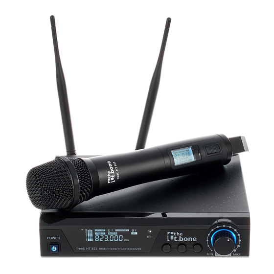
- Page 1 freeU HT, freeU PT UHF wireless system user manual...
- Page 2 Thomann GmbH Hans-Thomann-Straße 1 96138 Burgebrach Germany Telephone: +49 (0) 9546 9223-0 Internet: www.thomann.de 25.01.2022, ID: 405079, 405080, 405081, 405082, 405083, 405084 (V7)
-
Page 3: Table Of Contents
Table of contents Table of contents General information..........................5 1.1 Further information........................... 6 1.2 Notational conventions........................7 1.3 Symbols and signal words....................... 9 Safety instructions..........................10 Features............................... 13 Installation and starting up........................ 18 4.1 General Information........................18 4.2 Receiver............................... 19 4.3 Handheld microphone........................ - Page 4 Table of contents Operating..............................36 6.1 Receiver............................... 36 6.2 Handheld microphone........................40 6.3 Bodypack transmitter........................41 Technical specifications........................44 7.1 Receiver............................... 44 7.2 Handheld microphone........................47 7.3 Bodypack transmitter........................50 Plug and connection assignment....................53 Troubleshooting............................56 Protecting the environment......................59 UHF wireless system...
-
Page 5: General Information
Our products and user manuals are subject to a process of continuous development. We there‐ fore reserve the right to make changes without notice. Please refer to the latest version of the user manual which is ready for download under www.thomann.de. freeU HT, freeU PT... -
Page 6: Further Information
General information 1.1 Further information On our website (www.thomann.de) you will find lots of further information and details on the following points: Download This manual is also available as PDF file for you to download. Use the search function in the electronic version to find the topics of Keyword search interest for you quickly. -
Page 7: Notational Conventions
General information 1.2 Notational conventions This manual uses the following notational conventions: Letterings The letterings for connectors and controls are marked by square brackets and italics. Examples: [VOLUME] control, [Mono] button. Displays Texts and values displayed on the device are marked by quotation marks and italics. Examples: ‘24ch’... - Page 8 General information Instructions The individual steps of an instruction are numbered consecutively. The result of a step is indented and highlighted by an arrow. Example: Switch on the device. Press [Auto]. ð Automatic operation is started. Switch off the device. Cross-references References to other locations in this manual are identified by an arrow and the specified page number.
-
Page 9: Symbols And Signal Words
General information 1.3 Symbols and signal words In this section you will find an overview of the meaning of symbols and signal words that are used in this manual. Signal word Meaning DANGER! This combination of symbol and signal word indicates an immediate dangerous situation that will result in death or serious injury if it is not avoided. -
Page 10: Safety Instructions
Safety instructions Safety instructions Intended use This device is intended to be used for the wireless transmission of audio signals from micro‐ phones or instruments to amplifiers or active speakers. Use the device only as described in this user manual. Any other use or use under other operating conditions is considered to be improper and may result in personal injury or property damage. - Page 11 Safety instructions NOTICE! Operating conditions This device has been designed for indoor use only. To prevent damage, never expose the device to any liquid or moisture. Avoid direct sunlight, heavy dirt, and strong vibrations. Only operate the device within the ambient conditions specified in the chapter ‘Technical specifications’...
- Page 12 Safety instructions NOTICE! Risk of fire due to incorrect polarity Incorrectly inserted batteries may destroy the device or the batteries. Ensure that proper polarity is observed when inserting bat‐ teries. NOTICE! Possible damage by leaking batteries Leaking batteries can cause permanent damage to the device. Take batteries out of the device if it is not going to be used for a longer period.
-
Page 13: Features
UHF Wireless System freeU HT Item no. Name Frequency band 405081 the t.bone freeU HT 600 606 MHz…630 MHz 405079 the t.bone freeU HT 823 823 MHz…832 MHz 405083 the t.bone freeU HT 863... - Page 14 Features The UHF Wireless System freeU HT is comprised of the following components: 9.5" Diversity receiver – Two antennas for optimum reception quality – Infrared interface for sending the frequency selection from the receiver to the trans‐ mitter – Outputs: XLR, 1/4" jack socket –...
- Page 15 Features Item no. Name Pre-programmed fre‐ Available channels quency groups per group 405081 the t.bone freeU HT 600 405079 the t.bone freeU HT 823 405083 the t.bone freeU HT 863 UHF Wireless System freeU PT Item no. Name Frequency band 405082 the t.bone freeU PT 600...
- Page 16 Features The UHF Wireless System freeU PT is comprised of the following components: 9.5" Diversity receiver – Two antennas for optimum reception quality – Infrared interface for sending the frequency selection from the receiver to the trans‐ mitter – Outputs: XLR, 1/4" jack socket –...
- Page 17 Features Item no. Name Pre-programmed fre‐ Available channels quency groups per group 405082 the t.bone freeU PT 600 405080 the t.bone freeU PT 823 405084 the t.bone freeU PT 863 freeU HT, freeU PT...
-
Page 18: Installation And Starting Up
Installation and starting up Installation and starting up 4.1 General Information Unpack and check carefully there is no transportation damage before using the unit. Keep the equipment packaging. To fully protect the product against vibration, dust and moisture during transportation or storage use the original packaging or your own packaging material suitable for transport or storage, respectively. -
Page 19: Receiver
For more information, please visit: http://www.thomann.de. Make sure that transmitter and receiver are both tuned to the same channel. - Page 20 Installation and starting up Connect the power supply NOTICE! External power supply The device is powered by an external power supply. Before connecting the external power supply, ensure that the input voltage (AC outlet) matches the voltage rating of the device and that the AC outlet is protected by a residual cur‐ rent circuit breaker.
-
Page 21: Handheld Microphone
Installation and starting up Connecting audio and starting Connect one of the audio outputs of the receiver to your mixer or your amplifier. Ensure that only one of the two outputs is ever used at a time, because faults might occur otherwise. 4.3 Handheld microphone Inserting batteries Unscrew the bottom housing section of the handheld microphone. -
Page 22: Bodypack Transmitter
Installation and starting up 4.4 Bodypack transmitter Inserting batteries Squeeze the battery compartment lid, flip it open and and insert the batteries. Pay attention to the correct location of the poles. Close the battery compartment and switch the transmitter Connecting microphone of Ensure that the transmitter is switched off. -
Page 23: Connections And Controls
Connections and controls Connections and controls 5.1 Receiver Front panel POWER VOLUME ö % & ' freeU HT, freeU PT... - Page 24 Connections and controls 1 [POWER] Press the switch to switch the device on or off. All previous settings are retained even when you switch the device off and disconnect it from the mains. 2 Display 3 [IR] Infrared sensor Increases the displayed value by one. 5 [SET] Opens the menu.
- Page 25 Connections and controls 7 [VOLUME] Volume control to adjust the audio output level. 11 UHF antennas. freeU HT, freeU PT...
- Page 26 Connections and controls Rear panel BALANCED OUTPUT POWER INPUT UNBALANCED ANT B ANT A 12–18V=/500mA OUTPUT 8 [DC INPUT 12-18V] Socket for connecting the supplied AC power supply. If you are using a different power supply, observe the correct voltage, the polarity of the plug and the power consumption. 9 [UNBALANCED OUTPUT] 1/4"...
- Page 27 Connections and controls 10 [BALANCED OUTPUT] XLR panel plug as balanced audio signal output for direct connection to a mixer, a power amp or recording device. 11 [ANT A], [ANT B] UHF antenna connections. freeU HT, freeU PT...
- Page 28 Connections and controls Display 12 [AF] Level display for the audio signal. 13 [RF] Level indicator for the received radio signal. 14 [GROUP] Indicates the selected frequency group. 15 [CHANNEL] Indicates the selected channel. 16 [IR] Indicates data transfer via infrared interface. UHF wireless system...
- Page 29 Connections and controls 17 [ANT-A], [ANT-B] Shows which of the two antennas is currently being used for signal transmission. 18 [FREQ] Indicates the frequency that is assigned to the set combination of frequency group and channel. freeU HT, freeU PT...
-
Page 30: Handheld Microphone
Connections and controls 5.2 Handheld microphone < UHF wireless system... - Page 31 Connections and controls 21 Display 22 Microphone head grill to prevent damage and to reduce wind and breath noise. 23 Infrared sensor 24 Main switch Slide the switch all the way forward to turn on the microphone. Slide it all the way back to turn it off. Set the switch to the centre position to mute the microphone.
- Page 32 Connections and controls Display 28 Battery level indicator. Replace the batteries when only one blinking bar remains > displayed. Reduces the voltage of the batteries even further if the transmitter is automatically switched off. 29 [GROUP] Indicates the selected frequency group. 30 [CHANNEL] Indicates the selected channel.
-
Page 33: Bodypack Transmitter
Connections and controls 5.3 Bodypack transmitter NAME BANK FREQ 2X1.5V 2X1.5V freeU HT, freeU PT... - Page 34 Connections and controls 41 Display 42 Antenna Increases the displayed value by one. Opens the menu. Decreases the displayed value by one. 46 [IR] Infrared sensor 47 Battery holder for two round cell batteries (AA, LR06), 1.5 V or comparable rechargeable batteries. 48 Mini-XLR chassis plug for connecting a microphone or instrument.
- Page 35 Connections and controls 50 Main switch Press the switch for several seconds to switch the device on or off. 51 Retaining clamp Display 52, 53, [NAME], [BANK], [CH] No function. 55 [FREQ] NAME BANK Indicates the set frequency that is assigned to the set combination of frequency group and channel.
-
Page 36: Operating
Operating Operating 6.1 Receiver Turning the receiver on / off Turn on the power using the main switch. ð The display is activated. The device is operational. Now, you can make the desired settings. UHF wireless system... - Page 37 Use the arrow buttons to select the level for the radio signal in a range from 5 mW (PO.1) to 30 mW (PO.4) (this option is omitted for the t.bone freeU HT 863 and the t.bone freeU PT 863) .
- Page 38 Operating Check the frequency Press on the receiver repeatedly until the display shows ‘SCAN’ . ð The ‘SCAN’ display blinks. The device checks the set combination of frequency group and channel on possible interferences. If the set channel is free, the display shows the frequency with the status message ‘PF’...
- Page 39 Operating Synchronising the receiver with the transmitter Press and hold on the receiver until the display shows ‘F---’ . ð The ‘IR’ display blinks. Hold the infrared sensor of the transmitter near the infrared interface of the receiver. ð The settings of the receiver are transmitted to the transmitter. Once the synchronisation is finished, the display returns to the default state and ‘IR’...
-
Page 40: Handheld Microphone
Operating 6.2 Handheld microphone Turning the microphone on / off Slide the switch all the way forward (ON) to turn on the microphone. Slide the switch all the way back (OFF) to turn it off. Set the switch to the centre position to mute the microphone. Synchronising the receiver with the microphone Prepare the receiver for the synchronisation (... -
Page 41: Bodypack Transmitter
Operating 6.3 Bodypack transmitter Turn the bodypack transmitter on / off Briefly press the main switch on the top of the unit to turn the bodypack transmitter on. ð The display shows the frequency and the charging level of the batteries. The device is operational. - Page 42 Operating Synchronising the bodypack transmitter with the receiver Prepare the receiver for the synchronisation ( Ä ‘Synchronising the receiver with the trans‐ mitter’ on page 39). Press the lid of the battery compartment of the bodypack transmitter on one side and flip the lid open.
- Page 43 Operating Setting the frequency manually If you don't want to synchronise the transmitter with the receiver using the infrared interface, you can also set the transmission frequency manually. Press the lid of the battery compartment of the bodypack transmitter on one side and flip the lid open.
-
Page 44: Technical Specifications
Technical specifications Technical specifications 7.1 Receiver Input connections Power supply Socket for connecting the power adapter Output connections Audio signal output 1× 1/4" jack socket (unbalanced) Audio signal output 1 ×XLR panel plug, balanced Output level adjustment –32 dB … +0 dB Frequency range 50 Hz…16 kHz (±3 dB) Antenna gain... - Page 45 Technical specifications Operating voltage 12 V / 500 mA, centre positive Dimensions (W × H × D, without 210 mm × 44 mm × 170 mm antennas) Weight 865 g Ambient conditions Temperature range 0 °C…40 °C Relative humidity 20 %…80 % (non-condensing) Carrier frequency, frequency band, number of channels, bandwidth, switching bandwidth and modulation type correspond to those of the transmitter.
- Page 46 Technical specifications Further information Frequency band Diversity Switchable frequencies Detachable antennas Pilot tone UHF wireless system...
-
Page 47: Handheld Microphone
Technical specifications 7.2 Handheld microphone the t.bone freeU HT 600 the t.bone freeU HT 823 the t.bone freeU HT 863 (item no. 405081) (item no. 405079) (item no. 405083) Carrier frequency UHF band (600 MHz…952 MHz) Frequency range 606 MHz…630 MHz 823 MHz…832 MHz... - Page 48 Technical specifications the t.bone freeU HT 600 the t.bone freeU HT 823 the t.bone freeU HT 863 (item no. 405081) (item no. 405079) (item no. 405083) Number of channels 100 (10 pre-programmed fre‐ 100 (10 pre-programmed 16 (4 pre-programmed fre‐...
- Page 49 Technical specifications the t.bone freeU HT 600 the t.bone freeU HT 823 the t.bone freeU HT 863 (item no. 405081) (item no. 405079) (item no. 405083) Ambient condi‐ Temperature range 0 °C…40 °C tions Relative humidity 20 %…80 % (non-condensing)
-
Page 50: Bodypack Transmitter
Technical specifications 7.3 Bodypack transmitter the t.bone freeU PT 600 the t.bone freeU PT 823 the t.bone freeU PT 863 (item no. 405082) (item no. 405080) (item no. 405084) Carrier frequency UHF band (600 MHz…952 MHz) Frequency range 606 MHz…630 MHz 823 MHz…832 MHz 863 MHz…865 MHz Max. - Page 51 Technical specifications the t.bone freeU PT 600 the t.bone freeU PT 823 the t.bone freeU PT 863 (item no. 405082) (item no. 405080) (item no. 405084) Number of channels 100 (10 pre-programmed fre‐ 100 (10 pre-programmed 16 (4 pre-programmed fre‐ quency groups, each with 10 frequency groups, each quency groups, each with 4...
- Page 52 Technical specifications Further information the t.bone freeU PT 600 the t.bone freeU PT 823 the t.bone freeU PT (item no. 405082) (item no. 405080) 863 (item no. 405084) Max. number of radio links UHF wireless system...
-
Page 53: Plug And Connection Assignment
Plug and connection assignment Plug and connection assignment Introduction This chapter will help you select the right cables and plugs to connect your valuable equip‐ ment in such a way that a perfect sound experience is ensured. Please note these advices, because especially in ‘Sound & Light’ caution is indicated: Even if a plug fits into the socket, an incorrect connection may result in a destroyed power amp, a short circuit or ‘just’... - Page 54 Plug and connection assignment Since the interference affects both cores equally, by subtracting the phase-shifted signals, the interfering signal is completely neutralized. The result is a pure signal without any noise inter‐ ference. 1/4" TS phone plug (mono, unbalanced) Signal Ground, shielding 1/4"...
- Page 55 Plug and connection assignment XLR plug (balanced) Ground, shielding Signal (in phase, +) Signal (out of phase, –) Shielding on plug housing (option) Mini XLR Ground Positive signal (+) Negative signal (–) freeU HT, freeU PT...
-
Page 56: Troubleshooting
Troubleshooting Troubleshooting In the following we list a few common problems that may occur during operation. We give you some suggestions for easy troubleshooting: UHF wireless system... - Page 57 Troubleshooting Symptom Remedy No sound 1. Check the power supply of transmitter and receiver. 2. Make sure that transmitter and receiver are operating in the same frequency range. The frequency range can be found on the devices. 3. Are transmitter and receiver set to the same channel? 4.
- Page 58 2. If you use more than one wireless system at the same time, check the used frequencies and channels. 3. Interference can also be caused by other radio or in-ear systems. If the procedures recommended above do not succeed, please contact our Service Center. You can find the contact information at www.thomann.de. UHF wireless system...
-
Page 59: Protecting The Environment
Protecting the environment Protecting the environment Disposal of the packaging mate‐ rial For the transport and protective packaging, environmentally friendly materials have been chosen that can be supplied to normal recycling. Ensure that plastic bags, packaging, etc. are properly disposed of. Do not just dispose these materials with your normal household waste, but make sure that they are fed to a recovery. - Page 60 Protecting the environment Disposal of your old device This product is subject to the European Waste Electrical and Electronic Equipment Directive (WEEE) in its currently valid version. Do not dispose with your normal household waste. Dispose this device through an approved waste disposal firm or through your local waste facility.
- Page 61 Notes freeU HT, freeU PT...
- Page 62 Notes UHF wireless system...
- Page 64 Musikhaus Thomann · Hans-Thomann-Straße 1 · 96138 Burgebrach · Germany · www.thomann.de...
Need help?
Do you have a question about the the t.bone freeU HT and is the answer not in the manual?
Questions and answers