thomann the t.bone free solo PT 1.8 GHz User Manual
Hide thumbs
Also See for the t.bone free solo PT 1.8 GHz:
- User manual (56 pages) ,
- User manual (48 pages) ,
- User manual (52 pages)
Table of Contents
Advertisement
Quick Links
Advertisement
Table of Contents

Related Manuals for thomann the t.bone free solo PT 1.8 GHz


Summary of Contents for thomann the t.bone free solo PT 1.8 GHz
- Page 1 free solo PT 1.8 GHz, HT 1.8 GHz Wireless System...
- Page 2 Thomann GmbH Hans-Thomann-Straße 1 96138 Burgebrach Germany Telephone: +49 (0) 9546 9223-0 Internet: www.thomann.de 04.04.2024, ID: 323196, 323200 (V3)
-
Page 3: Table Of Contents
Table of contents Table of contents General information..........................6 1.1 Symbols and signal words....................... 6 Safety instructions............................. 8 Features............................... 10 Installation and starting up........................ 12 4.1 General Information........................12 4.2 Receiver............................... 13 4.3 Bodypack transmitter (item no. 323196)................. 14 4.4 Handheld microphone (item no. 323200)................15 Connections and controls........................ - Page 4 Table of contents 7.2 Bodypack transmitter (item no. 323196)................. 38 7.3 Handheld microphone (item no. 323200)................41 Plug and connection assignment....................43 Troubleshooting............................46 Protecting the environment......................48 free solo PT 1.8 GHz, HT 1.8 GHz Wireless System...
- Page 5 free solo PT 1.8 GHz, HT 1.8 GHz Wireless System...
-
Page 6: General Information
Our products and documentation are subject to a process of continuous development. They are therefore subject to change. Please refer to the latest version of the documentation, which is ready for download under www.thomann.de. 1.1 Symbols and signal words In this section you will find an overview of the meaning of symbols and signal words that are used in this document. - Page 7 General information Warning signs Type of danger Warning – danger zone. free solo PT 1.8 GHz, HT 1.8 GHz Wireless System...
-
Page 8: Safety Instructions
Safety instructions Safety instructions Intended use This device is intended to be used for the wireless transmission of audio signals from micro‐ phones or instruments to amplifiers or active speakers. Use the device only as described in this user manual. Any other use or use under other operating conditions is considered to be improper and may result in personal injury or property damage. - Page 9 Safety instructions NOTICE! Damage to the device if operated in unsuitable ambient conditions! The device can be damaged if it is operated in unsuitable ambient conditions. Only operate the device indoors within the ambient conditions specified in the “Technical specifications” chapter of this user manual. Avoid operating it in environments with direct sun‐ light, heavy dirt and strong vibrations.
-
Page 10: Features
Features Features free solo PT 1.8 GHz The wireless system is particularly suitable for professional audio transmission, for example, at (item no. 323196) events, on rock stages and in concert halls, theatres, musicals or night clubs. Your wireless system free solo HTPT is comprised of the following components: 9.5-inch diversity receiver –... - Page 11 Transmitter: Battery powered handheld cardioid microphone Depending on the ambient conditions, it is possible to operate up to six systems in parallel. The frequency lists are available for download on the product page at www.thomann.de. free solo PT 1.8 GHz, HT 1.8 GHz Wireless System...
-
Page 12: Installation And Starting Up
For more information, please visit: http://www.thomann.de. Make sure that transmitter and receiver are both tuned to the same channel. -
Page 13: Receiver
Installation and starting up 4.2 Receiver Rack mounting The device is designed for mounting in a standard 19-inch rack; it occupies one rack unit (RU). The fixing material required for assembly is included. Connecting the power supply NOTICE! Damage to the external power supply due to high voltages! The device is powered by an external power supply. -
Page 14: Bodypack Transmitter (Item No. 323196)
Installation and starting up Attaching the antennas Attach the included antennas to the back of the transmitter. The antenna can be rotated and swivelled to improve transmission quality and to adapt to spatial conditions. If there is not enough space on the device for direct assembly of the antennas, for example because there is not much space in the rack, you can use the optionally available coaxial cable to assemble the antennas separately from the device. -
Page 15: Handheld Microphone (Item No. 323200)
Installation and starting up Connecting a microphone or Ensure that the transmitter is switched off. instrument to the transmitter Connect the microphone cable or instrument cable to the input on the transmitter (mini- XLR panel connector). Turn on the transmitter and check the transmission by using the microphone or instru‐ ment. -
Page 16: Connections And Controls
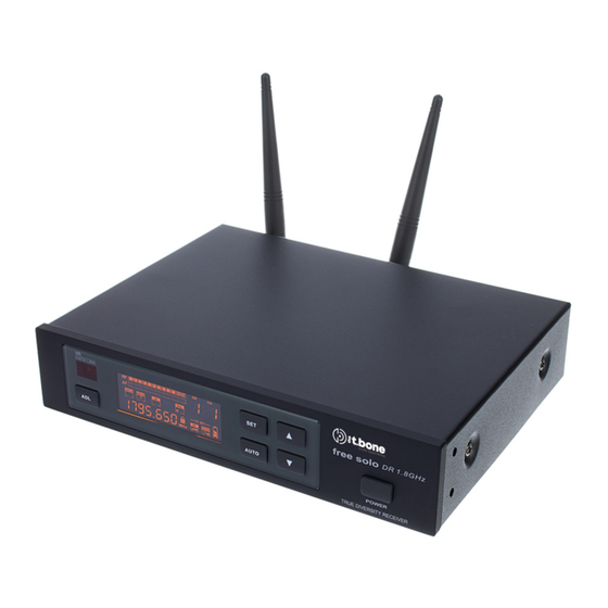
Connections and controls Connections and controls 5.1 Receiver Front panel ö ö & DATA LINK free solo 8888 ANT.A ANT.B AUTO TX SET 888[888 GAIN AUTO POWER TRUE DIVERSITY RECEIVER free solo PT 1.8 GHz, HT 1.8 GHz Wireless System... - Page 17 Connections and controls 1 Tuned UHF antennas. The receiver evaluates the radio signal coming from both antennas and selects the signal with the higher quality for further processing. 2 Infrared receiver 3 Display 4 [SET] | Opens the menu. | Increases the displayed value by one. 6 [POWER] | Press the switch for several seconds to switch the device on or off.
- Page 18 Connections and controls Rear panel FREQ. BALANCED UNBALANCED ANTENNA-B ANTENNA-A OUTPUT OUTPUT ö & free solo PT 1.8 GHz, HT 1.8 GHz Wireless System...
- Page 19 Connections and controls 1 [DC 12-18V] | Socket for connecting the supplied power supply. If you are using a different power supply, observe the correct voltage, the polarity of the plug and the power consumption. 2 [BALANCED OUTPUT] | XLR panel plug as balanced audio signal output for direct connection to a mixer, power ampli‐ fier or recording device.
- Page 20 Connections and controls Display ö 8888 ANT.A ANT.B AUTO TX SET 8888888 GAIN & free solo PT 1.8 GHz, HT 1.8 GHz Wireless System...
- Page 21 Connections and controls 1 [RF] | Shows the level of the received radio signal. 2 [AF] | Level display for the audio signal. 3 [GP] | Displays the selected frequency group. 4 [CH] | Displays the selected channel. 5 [GAIN] | Displays the signal gain or attenuation in dB. 6 [RF] | Shows the output power.
-
Page 22: Bodypack Transmitter (Item No. 323196)
Connections and controls 5.2 Bodypack transmitter (item no. 323196) ö ö BATT & MUTE 838 000 FREQUENCY ö GAIN free solo PT 1.8 GHz, HT 1.8 GHz Wireless System... - Page 23 Connections and controls 1 Display 2 Antenna 3 [MUTE] | Indicates that the device is muted. 4 [BATT LOW] / [ON] | Flashes when the battery level is too low. 5 [SET] | Opens the menu. | Increases or decreases the currently displayed value. 7 Battery holder for two round cell batteries (AA, LR06), 1.5 V or comparable rechargeable batteries.
- Page 24 Connections and controls 1 [FREQUENCY] / [GP] / [CH] | Depending on the selected menu item: ö Displays the frequency that is assigned to the set combination of frequency group and channel. Displays the set frequency group and the set channel. FREQUENCY 838 000 | Indicates that the device is locked to prevent unintentional changes.
-
Page 25: Handheld Microphone (Item No. 323200)
Connections and controls 5.3 Handheld microphone (item no. 323200) ö free solo free solo & free solo PT 1.8 GHz, HT 1.8 GHz Wireless System... - Page 26 Connections and controls 1 Microphone head grill to prevent damage and to reduce wind and breathing noises. 2 Display 3 Main switch. Press the switch for several seconds to switch the device on or off. Press the switch briefly to mute or unmute the microphone.
- Page 27 Connections and controls 1 [MHz] | Display of the set frequency. ö ö 2 Battery level indicator. Replace the batteries when only one blinking bar is dis‐ played. If the battery voltage drops any further the transmitter is switched off auto‐ matically.
-
Page 28: Operating
ð The [GP] display flashes. Use the arrow buttons to select the frequency group. The frequency lists are available for download on the product page at www.thomann.de. Press [SET] to confirm the selection. ð The [CH] display flashes. Use the arrow buttons to select a channel within the set frequency group. - Page 29 Operating ð The display shows that the receiver is being tuned to the new frequency. After a few seconds, the display shows the default state again. Synchronising transmitter and receiver Open the transmitter to expose the infrared sensor. Press [ADL] The [IR] display flashes. Hold the infrared sensor of the transmitter near the infrared interface of the receiver within ten seconds.
- Page 30 Operating Automatic search for a free channel Press [AUTO]. ð The [AUTO] display flashes, the display shows the number of free channels available. Use the arrow buttons to select one of the free channels. Press [SET] to confirm the selection. ð...
-
Page 31: Bodypack Transmitter (Item No. 323196)
Press [SET] repeatedly until the value in the [GP] field flashes on the display. Use the arrow buttons to select the frequency group. The frequency lists are available for download on the product page at www.thomann.de. Press [SET] to confirm the selection. ð The number in the [CH] field flashes. - Page 32 Operating Use the arrow buttons to select a channel within the set frequency group. If you have selected frequency group “U”, you can use the arrow buttons to set the fre‐ quency directly. First set the value before the decimal point and press [SET], then set the value after the decimal point.
-
Page 33: Handheld Microphone (Item No. 323200)
Operating Displaying the frequency group and channel Press . ð The display shows the frequency group and channel being used. Press [SET] or wait five seconds to return to normal state. Locking the keypad Press until the symbol appears. ð All buttons except for the main switch are locked. Unlocking the keypad To unlock the keypad, press until the symbol is no longer displayed. - Page 34 Press and hold [SET] until the value in the [GP] field flashes on the display. Use [SEL] to select the frequency group. The frequency lists are available for download on the product page at www.thomann.de. Press [SET] to confirm the selection. ð The number in the [CH] field flashes.
- Page 35 Operating Setting the gain Press and hold [SET] until the number in the [GAIN] field flashes on the display. Use [SEL] to change the transmitter gain in increments of 3dB (0dB, 3dB, 6dB). Press [SET] to confirm the selection. Press the main switch to close the menu without making any changes.
- Page 36 Operating Locking the keypad Press [SEL] until the symbol appears. ð All buttons except for the main switch are locked. Unlocking the keypad To cancel the key lock, press [SET] [SEL] [SET] [SEL] [SET] [SEL]. ð The buttons have their original function again. free solo PT 1.8 GHz, HT 1.8 GHz Wireless System...
-
Page 37: Technical Specifications
Technical specifications Technical specifications 7.1 Receiver Input connections Power supply Input socket for external power adapter Output connections Audio signal 1× XLR panel plug, balanced 1× 6.35-mm jack socket, unbalanced Output level adjustment +8 dB Sensitivity –102 dBm NF frequency response 50 Hz…15 kHz (±3 dB) Total harmonic distortion (THD) <... - Page 38 Technical specifications Ambient conditions Temperature range 0 °C…40 °C Relative humidity 20%…80% (non-condensing) Carrier frequency, frequency band, number of channels, bandwidth, switching bandwidth and modulation type correspond to those of the transmitter. 7.2 Bodypack transmitter (item no. 323196) Number of channels Frequency range 1.7815 GHz…1.7955 GHz Max.
- Page 39 Technical specifications Range of the infrared connection for the syn‐ 80 mm chronisation between transmitter and receiver NF frequency response 60 Hz…18 kHz Total harmonic distortion < 0.5% Switching bandwidth 25 kHz Spurious rejection > 55 dBc Peak deviation ± 55 kHz Signal-to-noise ratio >...
- Page 40 Technical specifications Further information Guitar channels Transmission technology Analogue Transmitter type Bodypack transmitter Receiver type Stationary Detachable antenna Charging system Built-in battery Suitable antenna converter Optionally available (item no. 177448) Accessories Guitar cable, rack mount and plastic case included free solo PT 1.8 GHz, HT 1.8 GHz Wireless System...
- Page 41 Technical specifications 7.3 Handheld microphone (item no. 323200) Number of channels Frequency range 1.7815 GHz…1.7955 GHz Max. transmission power 20 mW Maximum input level > 250 mV Frequency band UHF band Bandwidth 140 MHz Modulation type Frequency modulation (FM) Input impedance 5 KΩ...
- Page 42 Technical specifications Signal-to-noise ratio > 102 dB (A) Battery Battery type 2 round cell batteries (AA, LR06) or comparable rechargeable batteries Voltage 1.5 V Operating time > 8 h (with alkaline cells) Dimensions (L × D) 246 mm × 53 mm Weight 250 g Ambient conditions...
-
Page 43: Plug And Connection Assignment
Plug and connection assignment Plug and connection assignment Introduction This chapter will help you select the right cables and plugs to connect your valuable equip‐ ment in such a way that a perfect sound experience is ensured. Please note these advices, because especially in ‘Sound & Light’ caution is indicated: Even if a plug fits into the socket, an incorrect connection may result in a destroyed power amp, a short circuit or ‘just’... - Page 44 Plug and connection assignment 1/4" TS phone plug (mono, unbalanced) Signal Ground, shielding 1/4" TRS phone plug (mono, bal‐ anced) Signal (in phase, +) Signal (out of phase, –) Ground XLR plug (balanced) Ground, shielding Signal (in phase, +) Signal (out of phase, –) Shielding on plug housing (option) free solo PT 1.8 GHz, HT 1.8 GHz Wireless System...
- Page 45 Plug and connection assignment Mini-XLR connections for signal A mini-XLR panel plug serves as a signal input on the transmitter. The figure and the table input on the transmitter show the mini-XLR pin assignment. Ground Positive signal (+) Negative signal (–) free solo PT 1.8 GHz, HT 1.8 GHz Wireless System...
-
Page 46: Troubleshooting
Troubleshooting Troubleshooting In the following we list a few common problems that may occur during operation. We give you some suggestions for easy troubleshooting: Symptom Remedy No sound 1. Check the power supply of the transmitter and receiver. 2. Make sure that transmitter and receiver are operating in the same frequency range. - Page 47 3. Interference can also be caused by other radio or in-ear systems. If the procedures recommended above do not succeed, please contact our Service Center. You can find the contact information at www.thomann.de. free solo PT 1.8 GHz, HT 1.8 GHz...
-
Page 48: Protecting The Environment
Protecting the environment Protecting the environment Disposal of the packing material Environmentally friendly materials have been chosen for the packaging. These materials can be sent for normal recycling. Ensure that plastic bags, packaging, etc. are disposed of in the proper manner. Do not dispose of these materials with your normal household waste, but make sure that they are collected for recycling. - Page 49 When disposing of the device, comply with the rules and regulations that apply in your country. You can also return your old device to Thomann GmbH at no charge. Check the current conditions on www.thomann.de.
- Page 50 Notes free solo PT 1.8 GHz, HT 1.8 GHz Wireless System...
- Page 52 Musikhaus Thomann · Hans-Thomann-Straße 1 · 96138 Burgebrach · Germany · www.thomann.de...
Need help?
Do you have a question about the the t.bone free solo PT 1.8 GHz and is the answer not in the manual?
Questions and answers