HP Compaq Pro 4300 All-in-One Hardware Reference Manual
Business pc
Hide thumbs
Also See for Compaq Pro 4300 All-in-One:
- Maintenance and service manual (177 pages) ,
- Maintenance & serice manual (162 pages) ,
- Specification (57 pages)
Table of Contents
Advertisement
Advertisement
Table of Contents

Subscribe to Our Youtube Channel
Related Manuals for HP Compaq Pro 4300 All-in-One


Summary of Contents for HP Compaq Pro 4300 All-in-One
- Page 1 Hardware Reference Guide HP Compaq Pro 4300 All-in-One Business PC...
- Page 2 Nothing herein should be construed as constituting an additional warranty. HP shall not be liable for technical or editorial errors or omissions contained herein. This document contains proprietary information that is protected by copyright.
-
Page 3: About This Book
About This Book This guide provides basic information for upgrading this computer model. WARNING! Text set off in this manner indicates that failure to follow directions could result in bodily harm or loss of life. CAUTION: Text set off in this manner indicates that failure to follow directions could result in damage to equipment or loss of information. - Page 4 About This Book...
-
Page 5: Table Of Contents
Table of contents 1 Product Features ....................... 1 Overview ..........................1 Front Components ........................2 Side Components ........................3 Rear Components ........................3 Keyboard Features ........................4 Adjusting Tilt ........................... 5 2 Hardware Repair and Upgrade ..................6 Warnings and Cautions ......................6 Additional Information ...................... -
Page 7: Product Features
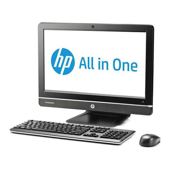
Product Features Overview Figure 1-1 HP Compaq Pro 4300 All-in-One Business PC The HP Compaq Pro 4300 All-in-One Business PC offers the following features: Integrated All-in-One form factor ● 20-inch diagonal widescreen 1600 x 900 WLED anti-glare display ● Adjustable tilt ●... -
Page 8: Front Components
Up to 16 GB of DDR3 SDRAM memory ● ● Optional wireless LAN (802.11 a/g/n, 802.11 a/g/n with Bluetooth ® Face Recognition for HP ProtectTools software with auto-login capabilities (only with the optional ● webcam) ● ENERGY STAR qualified, EPEAT Silver registered, and offers 89-percent energy-efficient power ®... -
Page 9: Side Components
Side Components Figure 1-3 Side Components Table 1-2 Side Components Component Component HP USB Media Card Reader Optical disc drive activity LED (2) USB 2.0 ports Tray-load optical disc drive Microphone/line in jack Brightness increase button Headphone jack Brightness decrease button... -
Page 10: Keyboard Features
Table 1-3 Rear Components Component Component Drive access panel Security lock slot Center access panel Power connector with LED indicator Memory access panel RJ-45 Gigabit Ethernet port Optical disc drive location Stereo audio line out Hard drive location (4) USB 2.0 ports Memory and battery location Serial port Keyboard Features... -
Page 11: Adjusting Tilt
Adjusting Tilt Tilt the computer forward up to -5 degrees or backward up to +25 degrees to set it to a comfortable eye level. Figure 1-6 Adjusting Tilt Adjusting Tilt... -
Page 12: Hardware Repair And Upgrade
To reduce the risk of serious injury, read the Safety & Comfort Guide. It describes proper workstation, setup, posture, and health and work habits for computer users, and provides important electrical and mechanical safety information. This guide is located on the Web at http://www.hp.com/ergo. WARNING! Computers that are inappropriately situated on dressers, bookcases, shelves, desks, speakers, chests, or carts may fall over and cause personal injury. -
Page 13: Additional Information
For more information on removing and replacing hardware components, the Computer Setup utility, and troubleshooting, refer to the Maintenance and Service Guide (available in English only) for your computer model at http://www.hp.com. Connecting Power Plug the power cord into the power connection on the rear of the computer (1). -
Page 14: Removing And Installing Memory
Hard drive ● Optical disc drive ● Figure 2-2 Locating Internal Components Component Component Optical disk drive Memory and battery compartment Hard drive Removing and Installing Memory The computer comes with double data rate 3 synchronous dynamic random access memory (DDR3- SDRAM) small outline dual inline memory modules (SODIMMs). - Page 15 Remove/disengage any security devices that prohibit opening the computer. Place the computer face down on a soft flat surface. HP recommends that you set down a blanket, towel, or other soft cloth to protect the screen surface from scratches or other damage.
- Page 16 Remove the center access panel by pulling outward on the panel at the slot on the top edge of the panel. Figure 2-3 Removing the Center Access Panel Open the latch securing the memory access panel. Figure 2-4 Opening the Memory Access Panel Latch Chapter 2 Hardware Repair and Upgrade...
- Page 17 To remove the memory access panel, press down on the tab on the inside edge of the panel (1) and slide the panel off the computer (2). Figure 2-5 Removing the Memory Access Panel Pull upward on the raised tab on the memory cover and lift the cover off the computer. Figure 2-6 Removing the Memory Cover Removing and Installing Memory...
- Page 18 To remove a memory module, press outward on the two latches on each side of the SODIMM (1), then pull the SODIMM out of the socket (2). Figure 2-7 Removing a Memory Module To install a memory module, slide the SODIMM into the socket at approximately a 30° angle (1), then press the SODIMM down (2) so that the latches lock it in place (3).
- Page 19 Press the memory cover back in place. Insert the bottom edge of the memory cover into the sheet metal shielding first, then press the top edge of memory cover down. Ensure that all the tabs on the memory cover are pressed firmly against the sheet metal shielding. Figure 2-9 Replacing the Memory Cover Place the memory access panel on the rear of the computer so that the edge of the panel is slightly...
-
Page 20: Replacing The Battery
Do not expose to temperatures higher than 60° C (140º F). Do not disassemble, crush, puncture, short external contacts, or dispose of in fire or water. Replace the battery only with the HP spare designated for this product. CAUTION: Before replacing the battery, it is important to back up the computer CMOS settings. - Page 21 Remove/disengage any security devices that prohibit opening the computer. Place the computer face down on a soft flat surface. HP recommends that you set down a blanket, towel, or other soft cloth to protect the screen surface from scratches or other damage.
- Page 22 Open the latch securing the memory access panel. Figure 2-13 Opening the Memory Access Panel Latch To remove the memory access panel, press down on the tab on the inside edge of the panel (1) and slide the panel off the computer (2). Figure 2-14 Removing the Memory Access Panel Chapter 2 Hardware Repair and Upgrade...
- Page 23 Pull upward on the raised tab on the memory cover and lift the cover off the computer. Figure 2-15 Removing the Memory Cover Depending on the type of battery holder on the system board, complete the following instructions to replace the battery. Type 1 Lift the battery out of its holder.
- Page 24 To insert the new battery, slide one edge of the replacement battery under the holder’s lip with the positive side up. Push the other edge down until the clamp snaps over the other edge of the battery (2). Figure 2-17 Removing and Replacing a Coin Cell Battery (Type 2) Type 3 Pull back on the clip (1) that is holding the battery in place, and remove the battery (2).
- Page 25 Press the memory cover back in place. Insert the bottom edge of the memory cover into the sheet metal shielding first, then press the top edge of memory cover down. Ensure that all the tabs on the memory cover are pressed firmly against the sheet metal shielding. Figure 2-19 Replacing the Memory Cover Place the memory access panel on the rear of the computer so that the edge of the panel is slightly...
-
Page 26: Replacing The Hard Drive
Remove/disengage any security devices that prohibit opening the computer. Place the computer face down on a soft flat surface. HP recommends that you set down a blanket, towel, or other soft cloth to protect the screen surface from scratches or other damage. - Page 27 Remove the center access panel by pulling outward on the panel at the slot on the top edge of the panel. Figure 2-22 Removing the Center Access Panel Open the latch securing the drive access panel. Figure 2-23 Opening the Drive Access Panel Latch Replacing the Hard Drive...
- Page 28 To remove the drive access panel, push downward on the tab on the inside edge of the panel (1) and slide the panel off the computer (2). Figure 2-24 Removing the Drive Access Panel Loosen the captive screw next to the front of the drive that secures the drive to the computer. Figure 2-25 Loosening the Hard Drive Security Screw Chapter 2 Hardware Repair and Upgrade...
- Page 29 Grasp the handle on top of the hard drive cage (1) and slide the cage toward the outer edge of the computer, then lift the cage out of the computer (2). Figure 2-26 Removing the Hard Drive Cage Remove the four mounting screws that secure the drive to the cage. Do not remove the blue rubber grommets behind each screw.
- Page 30 3.5-inch hard drive. The drive adapter may be part of the drive kit, or you may need to purchase it separately. It is recommended that you purchase a drive kit from HP that is designed to operate with the computer.
- Page 31 Install the four mounting screws that secure the hard drive to the cage. Make sure that the blue rubber grommets remain attached to the cage behind each screw. Figure 2-30 Installing the Hard Drive Mounting Screws Set the hard drive cage down into the bay so that the tabs on the bottom of the cage align with the slots on the chassis and slide the cage toward the center of the computer (1) so that the connector on the rear of the drive is securely seated.
- Page 32 Tighten the captive screw to secure the hard drive cage in place. Figure 2-32 Tightening the Hard Drive Security Screw Place the drive access panel on the rear of the computer so that the edge of the panel is slightly hanging off the edge of the computer and slide the panel toward the center of the computer until it snaps in place.
-
Page 33: Replacing The Optical Disc Drive
Remove/disengage any security devices that prohibit opening the computer. Place the computer face down on a soft flat surface. HP recommends that you set down a blanket, towel, or other soft cloth to protect the screen surface from scratches or other damage. - Page 34 Remove the center access panel by pulling outward on the panel at the slot on the top edge of the panel. Figure 2-35 Removing the Center Access Panel Open the latch securing the drive access panel. Figure 2-36 Opening the Drive Access Panel Latch Chapter 2 Hardware Repair and Upgrade...
- Page 35 To remove the drive access panel, push downward on the tab on the inside edge of the panel (1) and slide the panel off the computer (2). Figure 2-37 Removing the Drive Access Panel Remove the screw through the tab on the end of the drive that secures the drive to the computer. Figure 2-38 Removing the Optical Disc Drive Security Screw Replacing the Optical Disc Drive...
- Page 36 Using your fingers, press the visible edge of the optical disc drive toward the side of the computer to push the drive partially out of the computer. Grasp the front end of the drive and pull the drive out of the computer. Figure 2-39 Removing the Optical Disc Drive Align the new optical disc drive with the opening in the side of the computer.
- Page 37 Replace the screw to secure the optical disc drive in place. Figure 2-41 Installing the Optical Disc Drive Security Screw Place the drive access panel on the rear of the computer so that the edge of the panel is slightly hanging off the edge of the computer and slide the panel toward the center of the computer until it snaps in place.
-
Page 38: Installing A Security Lock
To replace the center access panel, insert the bottom edge of the panel, then press down firmly on each side of the panel working from the bottom to the top so that the panel snaps securely in place. Figure 2-43 Replacing the Center Access Panel Lock any security devices that were disengaged when the center access panel was removed. -
Page 39: Appendix A Electrostatic Discharge
● Use a portable field service kit with a folding static-dissipating work mat. ● If you do not have any of the suggested equipment for proper grounding, contact an HP authorized dealer, reseller, or service provider. NOTE: For more information on static electricity, contact an HP authorized dealer, reseller, or service provider. -
Page 40: Appendix B Computer Operating Guidelines, Routine Care And Shipping Preparation
Computer Operating Guidelines, Routine Care and Shipping Preparation Computer Operating Guidelines and Routine Care Follow these guidelines to properly set up and care for the computer: Keep the computer away from excessive moisture, direct sunlight, and extremes of heat and cold. ●... -
Page 41: Optical Disc Drive Precautions
CAUTION: If any object or liquid falls into the drive, immediately unplug the computer and have it checked by an authorized HP service provider. Shipping Preparation Follow these suggestions when preparing to ship the computer: Back up the hard drive files on optical media or external USB drives. -
Page 42: Index
Index additional information 7 memory installing 8 removing 8 battery replacement 14 specifications 8 components optical disc drive front 2 precautions 35 rear 3 replacing 27 side 3 components, internal 7 computer operating guidelines 34 power, connecting 7 electrostatic discharge, preventing rear components 3 damage 33 removing battery 14...
Need help?
Do you have a question about the Compaq Pro 4300 All-in-One and is the answer not in the manual?
Questions and answers