Table of Contents
Advertisement
Quick Links
Advertisement
Table of Contents

Subscribe to Our Youtube Channel
Related Manuals for Motorola EX-3524


Summary of Contents for Motorola EX-3524
- Page 1 EX-3524/EX-3548 Layer 2 Gigabit Ethernet PoE/PoE+ Switch INSTALLATION GUIDE...
- Page 2 EX-3524/EX-3548 Layer 2 Gigabit Ethernet PoE/PoE+ Switch Zebra and the Zebra head graphic are registered trademarks of ZIH Corp. The Symbol logo is a registered trademark of Symbol Technologies, Inc., a Zebra Technologies company. © 2015 Symbol Technologies, Inc.
-
Page 3: Table Of Contents
Installation Guide 1.0 Introduction ............5 1.1 Unpacking . - Page 4 EX-3524/EX-3548 Layer 2 Gigabit Ethernet PoE/PoE+ Switch 3.4 Port Connections..........20 3.4.1 Installing SFP Transceivers .
-
Page 5: Introduction
Installation Guide 1 Introduction The EX-3524 and EX-3548 are Gigabit Ethernet Layer 2 switches with either 24 or 48 10/100/1000-BASE-T ports, and four Small Form Factor Pluggable (SFP) transceiver slots for fiber connectivity. The switches are built with leading-edge technology to deliver reliable high-performance connectivity for your data network. -
Page 6: Warnings
Dispose of used batteries according to the instructions. • Use an Uninterruptible Power Supply (UPS) that supports the EX-3524/EX-3548 switch power rating. Not using a UPS can result in data loss or equipment damage due to a power surge or power failure. -
Page 7: Selecting A Site
Installation Guide 1.5 Selecting a Site Switch units can be mounted in a standard 19 inch equipment rack or on a flat surface. Be sure to follow the guidelines listed below when choosing a site: • Locate the switch unit at the center of all devices you want to link and near a power outlet. •... -
Page 8: Specifications
Form factor 1U rack mount Dimensions (WxDxH) EX-3524: 44.0 x 28.0 x 4.4 cm (17.32 x 11.00 x 1.73 in) EX-3548: 44.0 x 40.9 x 4.4 cm (17.32 x 16.10 x 1.73 in) Weight EX-3524: 3.6 kg (7.83 lb) EX-3548: 6.6 Kg (14.55 lb) 2.2 Environmental Specifications... -
Page 9: Power Cord Specifications
Installation Guide 2.4 Power Cord Specifications A power cord is not supplied with the EX-3524/EX3548 switch. Use only a correctly rated power cord certified (as appropriate) for the country of operation. 2.4.1 Power Protection • If possible, use a circuit dedicated to data processing equipment. Commercial electrical contractors are familiar with wiring for data processing equipment and can help with the load balancing of these circuits. -
Page 10: Port Leds
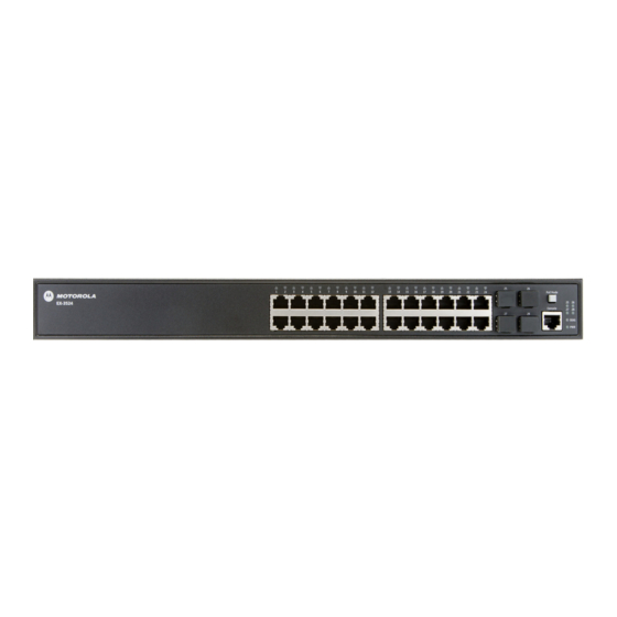
EX-3524/EX-3548 Layer 2 Gigabit Ethernet PoE/PoE+ Switch 2.5.1 Port LEDs For information on port status LED indicators, see Port Status LEDs on page 13. 2.5.2 10/100/1000BASE-T RJ-45 Ports The switch contains 24 10/100/1000BASE-T RJ-45 ports that support 10/100/1000BASE-T copper links to other devices. -
Page 11: Ground Point
Installation Guide 2.5.8 Ground Point The switch should be connected to ground using this screw connection. For more information on how to connect ground to the switch, see Power and Grounding on page 18. 2.5.9 AC Power Socket The switch requires a 100-240 VAC, 50-60 Hz AC power source. For more information on the switch power input, how to connect it, and how to power-on the switch, see Power and Grounding on page 18. -
Page 12: Led Codes
EX-3524/EX-3548 Layer 2 Gigabit Ethernet PoE/PoE+ Switch 2.6 LED Codes 2.6.1 System Status LEDs The diagnostic and power LEDs located on the front panel are shown below and described in the following table: Condition Status DIAG Green Solid System diagnostic test completed successfully... -
Page 13: Port Status Leds
Installation Guide 2.6.2 Port Status LEDs The switch includes LEDs for each port to indicate link status and network activity. The port LEDs are shown below and described in the following table: Condition Status 1000BASET RJ-45 Ports (1 - 24 or 1 - 48) Link/Activity On/Blinking Amber Port has a valid 10/100 Mbps link. -
Page 14: Hardware Installation
EX-3524/EX-3548 Layer 2 Gigabit Ethernet PoE/PoE+ Switch Hardware Installation The switch is designed to be installed in either a standard 19-inch equipment rack or simply placed on a suitable desktop or shelf surface. If you will mount your switch in a rack then plan your rack installation and install the switch chassis in the rack. - Page 15 Installation Guide 2. Use the supplied rack mounting screws to secure the switch in the rack.
- Page 16 EX-3524/EX-3548 Layer 2 Gigabit Ethernet PoE/PoE+ Switch 3. Connect an external AC power source to the AC power socket. 4. Verify basic switch operation by observing the system LEDs. For normal operation, both the DIAG and PWR LEDs should be solid green.
- Page 17 Installation Guide 5. Install the SFP transceivers and connect the cables to the port interfaces. • For RJ-45 ports, use 100-ohm category 3 or better Ethernet cable for 10BASE-T connections, use 100-ohm category 5 or better Ethernet cable for 100BASE-TX and 1000BASE-T connections. •...
-
Page 18: Shelf Or Desktop Installation
3.3 Power and Grounding The switches require power from an external AC power supply that can provide 100 to 240 VAC, 50-60 Hz. A standard AC power socket is located on the rear panel EX-3524 (left) and EX-3548 (right) of the each switch. - Page 19 Installation Guide The rear panel of the switch chassis includes a single hole grounding terminal. It must be connected to ground to ensure proper operation and to meet electromagnetic interference (EMI) and safety requirements. To ground the switch chassis: 1. Ensure the rack on which the switch is to be mounted is properly grounded and in compliance with ETSI ETS 300 253.
-
Page 20: Port Connections
EX-3524/EX-3548 Layer 2 Gigabit Ethernet PoE/PoE+ Switch 3.4 Port Connecctions 3.4.1 Installing SFP Transceivers The switch provides slots for optional (not provided) SFP transceivers. The supported transceiver types are listed below: • 1000BASE-SX • 1000BASE-LX • 1000BASE-LH • 1000BASE-FX • 1000BASE-T SPF transceivers are hot-swappable. -
Page 21: Connecting Twisted-Pair Cables
Installation Guide 4. Slide the transceiver into the slot until it clicks into place. If you do not immediately connect a cable to the port, use a rubber protective cap to keep the transceiver optics clean. To remove a transceiver, disconnect the network cable then pull the tab NOTE to remove the transceiver from the slot. -
Page 22: Power-Over-Ethernet
For the EX-3524, the total PoE power delivered by all ports cannot exceed the 390 W power budget. This means up to 12 ports can supply a maximum 30 W of power simultaneously to connected devices, or all 24 ports can supply a maximum of 15.4 W. -
Page 23: Connecting To Sfp Ports
Installation Guide 3.4.5 Connecting to SFP Ports The switch provides four ports for SFP-compliant fiber-optic transceivers. All 1000BASE fiber optic ports operate at 1 Gbps full duplex. The 100BASE fiber optic ports operate at 100 Mbps full duplex. Fiber Maximum Cable Cable Type Bandwidth Length... - Page 24 EX-3524/EX-3548 Layer 2 Gigabit Ethernet PoE/PoE+ Switch 3. Connect one end of the cable to the SFP port on the switch and the other end to the SFP port on the other device. Since SFP connectors are keyed, the cable can be attached in only one orientation.
-
Page 25: Switch Management
Installation Guide Switch Management The RJ-45 Console port on the front panel of the switch is used to connect a console device to the switch for out-of-band console configuration. The console device can be a PC or workstation running a VT-100 terminal emulator, or a VT-100 terminal. -
Page 26: Resetting The Switch
EX-3524/EX-3548 Layer 2 Gigabit Ethernet PoE/PoE+ Switch 3. Configure the PC’s COM port required settings using VT-100 terminal emulator software (such as HyperTerminal) running on the management PC. The switch’s default console port settings are: • 115200 bps, 8 data bits, 1-stop bit and no parity 4. - Page 27 Installation Guide Press Button Duration Result Less than 3 seconds No change to settings From 3 seconds to less than 6 seconds Switch reboots using saved configuration file 6 seconds or greater Switch reboots using factory default settings...
-
Page 28: Regulatory Overview
EX-3524/EX-3548 Layer 2 Gigabit Ethernet PoE/PoE+ Switch Regulatory Overview This guide applies to the following model numbers: EX-3524 and EX-3548. All Zebra devices are designed to be compliant with rules and regulations in locations they are sold and will be labeled as required. -
Page 29: Pse Alarm
Installation Guide Japan Voluntary Control Council for Interference (VCCI) Class A ITE Korea Warning Statement for Class A ITE Chinese Warning Statement for Class A ITE 5.5 PSE Alarm 5.6 Power Cord Safety Please read the following safety information carefully before installing the switch: Warning: Installation and removal of the unit must be carried out by qualified personnel only. - Page 30 EX-3524/EX-3548 Layer 2 Gigabit Ethernet PoE/PoE+ Switch This unit operates under SELV (Safety Extra Low Voltage) conditions according to IEC 60950. The conditions are only maintained if the equipment to which it is connected also operates under SELV conditions. France and Peru only This unit cannot be powered from IT†...
- Page 31 Installation Guide La prise secteur doit se trouver à proximité de l’appareil et son accès doit être facile. Vous ne pouvez mettre l’appareil hors circuit qu’en débranchant son cordon électrique au niveau de cette prise. L’appareil fonctionne à une tension extrêmement basse de sécurité qui est conforme à la norme IEC 60950. Ces conditions ne sont maintenues que si l’équipement auquel il est raccordé...
- Page 32 EX-3524/EX-3548 Layer 2 Gigabit Ethernet PoE/PoE+ Switch Die Netzsteckdose muß in der Nähe des Geräts und leicht zugänglich sein. Die Stromversorgung des Geräts kann nur durch Herausziehen des Gerätenetzkabels aus der Netzsteckdose unterbrochen werden. Cordon électrique - Il doit être agréé dans le pays d’utilisation Etats-Unis et Le cordon doit avoir reçu l’homologation des UL et un certificat de la CSA.
-
Page 33: Waste Electrial And Electronic Equipment (Weee)
Installation Guide 5.7 Waste Electrical and Electronic Equipment (WEEE) English: For EU Customers: All products at the end of their life must be returned to Zebra for recycling. For information on how to return product, please go to: www.zebra.com/weee. Français: Clients de l'Union Européenne: Tous les produits en fin de cycle de vie doivent être retournés à Zebra pour recyclage. - Page 34 EX-3524/EX-3548 Layer 2 Gigabit Ethernet PoE/PoE+ Switch Malti: Għal klijenti fl-UE: il-prodotti kollha li jkunu waslu fl-aħħar tal-ħajja ta' l-użu tagħhom, iridu jiġu rritornati għand Zebra għar-riċiklaġġ. Għal aktar tagħrif dwar kif għandek tirritorna l-prodott, jekk jogħġbok żur: www.zebra.com/weee. Românesc: Pentru clienţii din UE: Toate produsele, la sfârşitul duratei lor de funcţionare, trebuie returnate la Zebra pentru reciclare.
-
Page 35: Support
Installation Guide Support If you have a problem with your equipment, contact support for your region. Contact information is available at: www.zebra.com/support. When contacting support, please provide the following information: • Serial number of the unit • Model number or product name •... - Page 36 Zebra Technologies Corporation Lincolnshire, IL 60069 USA Zebra and the Zebra head graphic are registered trademarks of ZIH Corp. The Symbol logo is a registered trademark of Symbol Technologies, Inc., a Zebra Technologies company. © 2015 Symbol Technologies, Inc. MN001686A01 Revision A April 2015...
Need help?
Do you have a question about the EX-3524 and is the answer not in the manual?
Questions and answers