JVC EX-A1 Service Manual
Hide thumbs
Also See for EX-A1:
- Service manual (160 pages) ,
- Instructions manual (132 pages) ,
- Instructions manual (47 pages)
Advertisement
Quick Links
SERVICE MANUAL
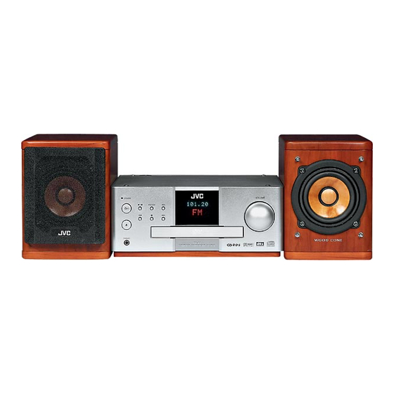
COMPACT COMPONENT SYSTEM
3
2004
MB150
1
PRECAUTION. . . . . . . . . . . . . . . . . . . . . . . . . . . . . . . . . . . . . . . . . . . . . . . . . . . . . . . . . . . . . . . . . . . . . . . . . 1-3
2
SPECIFIC SERVICE INSTRUCTIONS . . . . . . . . . . . . . . . . . . . . . . . . . . . . . . . . . . . . . . . . . . . . . . . . . . . . . . 1-6
3
DISASSEMBLY . . . . . . . . . . . . . . . . . . . . . . . . . . . . . . . . . . . . . . . . . . . . . . . . . . . . . . . . . . . . . . . . . . . . . . . 1-7
4
ADJUSTMENT . . . . . . . . . . . . . . . . . . . . . . . . . . . . . . . . . . . . . . . . . . . . . . . . . . . . . . . . . . . . . . . . . . . . . . . 1-22
5
TROUBLESHOOTING . . . . . . . . . . . . . . . . . . . . . . . . . . . . . . . . . . . . . . . . . . . . . . . . . . . . . . . . . . . . . . . . . 1-25
EX-A1
SP-EXA1
TABLE OF CONTENTS
COPYRIGHT © 2004 VICTOR COMPANY OF JAPAN, LIMITED
CA-EXA1
Area suffix
J ----------------------------- U.S.A.
C -------------------------- Canada
SP-EXA1
No.MB150
2004/3
Advertisement

Related Manuals for JVC EX-A1


Summary of Contents for JVC EX-A1
-
Page 1: Table Of Contents
SERVICE MANUAL COMPACT COMPONENT SYSTEM MB150 2004 EX-A1 Area suffix J ----------------------------- U.S.A. C -------------------------- Canada SP-EXA1 CA-EXA1 SP-EXA1 TABLE OF CONTENTS PRECAUTION............... . . 1-3 SPECIFIC SERVICE INSTRUCTIONS . - Page 2 SPECIFICATION General Power source AC 120 V 60 Hz Power consumption 24 W (in operation) 0.8 W (on standby) Weight 3.0 kg (6.7 lbs) External dimensions (W × H × D) 232 mm × 100 mm × 269 mm (9 3/16 inches × 3 15/16 inches × 10 5/8 inches) DVD player Playable discs DVD VIDEO, DVD AUDIO, VCD, Super VCD, CD, CD-R/RW (CD, VCD, MP3, JPEG format), DVD-R/ RW (video format)
-
Page 3: Precaution
SECTION 1 PRECAUTION Safety Precautions (1) This design of this product contains special hardware and voltmeter. many circuits and components specially for safety purpos- Move the resistor connection to each exposed metal es. For continued protection, no changes should be made part, particularly any exposed metal part having a return to the original design unless authorized in writing by the path to the chassis, and measure the AC voltage across... - Page 4 Preventing static electricity Electrostatic discharge (ESD), which occurs when static electricity stored in the body, fabric, etc. is discharged, can destroy the laser diode in the traverse unit (optical pickup). Take care to prevent this when performing repairs. 1.5.1 Grounding to prevent damage by static electricity Static electricity in the work area can destroy the optical pickup (laser diode) in devices such as laser products.
- Page 5 Importance administering point on the safety F2401 Main board Caution: For continued protection against risk of fire, replace only with same type 6A/125V for F2401. This symbol specifies type of fast operating fuse. Precaution: Pour eviter risques de feux, remplacez le fusible de surete de F2401 comme le meme type que 6A/125 V.
-
Page 6: Specific Service Instructions
SECTION 2 SPECIFIC SERVICE INSTRUCTIONS This service manual does not describe SPECIFIC SERVICE INSTRUCTIONS. 1-6 (No.MB150) -
Page 7: Disassembly
SECTION 3 DISASSEMBLY Main body section 3.1.1 Removing the top cover (See Fig.1) (1) From the top side of the main body, remove the four screws A attaching the top cover. Top cover Fig.1 3.1.2 Removing the AL panel L and AL panel R (See Figs.2 to 7.) •... - Page 8 Fig.3 AL panel L AL panel R AL panel R AL panel L Fig.6 AL panel R AL panel L Fig.4 Wood bar Fig.7 Fig.5 1-8 (No.MB150)
-
Page 9: See Fig.
3.1.3 Removing the front panel assembly (See Fig.8) • Remove the top cover. Front panel assembly • Remove the AL panel L and AL panel R. (1) Removing the three screws J attaching the front panel as- CN704 sembly. (See Fig.8.) (2) Release the claws a attaching the front panel assembly and remove the front panel assembly in the direction of the arrow. -
Page 10: See Fig.
3.1.6 Removing the tuner (See Figs.11 and 12) • Remove the top cover. Lug wire Bridge C • Remove the rear panel. (1) From the top side of the main body, remove the screw N and screw N' attaching the bridge C. (See Fig.11.) Reference: When attaching the screw N', attach the lug wire with it. - Page 11 3.1.8 Removing the main board (See Figs.14 and 15) • Remove the top cover. Digital amplifier Micom board • Remove the AL panel L and AL panel R. board assembly • Remove the rear panel. Main board Wires • Remove the switching power unit. CN204 CN312 Reference:...
- Page 12 3.1.9 Removing the micom board (See Figs.16 and 17) • Remove the top cover. Tuner holder • Remove the AL panel L and AL panel R. Tuner Card wires • Remove the front panel assembly. Wire Joints g • Remove the rear panel. •...
- Page 13 3.1.10 Removing the digital amplifier board (See Figs.18 to 20) • Remove the top cover. Deus case A • Remove the AL panel L and AL panel R. Joints r • Remove the front panel assembly. Joints p • Remove the rear panel. •...
- Page 14 3.1.11 Removing the speaker terminal board (See Fig.21.) • Remove the top cover. Component video terminal board • Remove the AL panel L and AL panel R. • Remove the front panel assembly. Joint z Wire • Remove the rear panel. Speaker terminal board •...
-
Page 15: No.mb150)1
3.1.14 Removing the fan motor (See Figs.21,23 and 24) • Remove the top cover. Wire CN703 • Remove the AL panel L and AL panel R. • Remove the rear panel. • Remove the switching power unit. • Remove the main board. (1) From the top side of the main body, disconnect the wire from the connector CN703... - Page 16 3.1.15 Removing the front board (See Figs.25 and 26) • Remove the top cover. Front panel assembly • Remove the AL panel L and AL panel R. • Remove the front panel assembly. (1) From the forward side of the front panel assembly, pull out the volume assembly.
- Page 17 DVD mechanism section • Remove the DVD mechanism assembly from the main body. (See "3.1.13 Removing the DVD mechanism assembly".) 3.2.1 Removing the tray assembly (See Figs.1 to 3) (1) From the right side of the DVD mechanism assembly, push Tray assembly DVD mechanism assembly the slide cam and pull the tray assembly out of the DVD...
- Page 18 3.2.2 Removing the traverse mechanism assembly (See Figs.4) (1) From the bottom side of the DVD mechanism assembly, DVD mechanism assembly remove the four screws B attaching the traverse mechanism assembly and take out the DVD traverse DVD servo board mechanism assembly with the DVD servo board.
- Page 19 3.2.4 Removing the pickup (See Figs.5,7 to 9) • Remove the traverse mechanism assembly. Thrust spring Plate (1) From the side of the traverse mechanism assembly, solder the short land sections c on the pickup. (See Fig.5.) (2) Release the lock of the connector on the pickup in the direction of the arrow and disconnect the card wire.
- Page 20 3.2.5 Attaching the pickup (See Figs.5,7 to 10) • See "3.2.4 Removing the pickup". Feed gear M (1) Attach the shaft, SW actuator and LEAD spring to the pickup. (See Fig.9.) (2) Align the pickup to the section j of the traverse mechanism assembly first, and set the both ends of the shaft of the pickup in the sections g and i of the traverse mechanism assembly.
- Page 21 3.2.7 Removing the spindle motor board (See Figs.11 and 13) • Remove the traverse mechanism assembly. Traverse mechanism assembly • Remove the DVD servo board. (1) From the top side of the traverse mechanism assembly, remove the wires from the soldered section k on the spindle motor board.
-
Page 22: Adjustment
SECTION 4 ADJUSTMENT Jigs and test instruments Adjustment and check items • Upgrade disc (1) Initialization of EEPROM (DVD unit) • Remote controller (2) About upgrade of DVD unit firm (3) About upgrade of system micom (ROM correction) (4) Confirming the version of unit and system firm and region code Adjustment and check method 4.3.1 Initialization of EEPROM (DVD unit) - Page 23 4.3.2 About UPGRADE of DVD UNIT firm 4.3.3 About UPGRADE of SYSTEM MICOM. (ROM CORRECTION) *This set can upgrade the DVD unit firm *This set can upgrade the SYSTEM MICOM using UPGRADE DISC. using UPGRADE DISC. Confirm condition, source:DVD, Confirm condition, source:DVD, indication:"NO DISC"...
- Page 24 4.3.4 Confirming the version of unit and system firm and Region Code (1) Push "STOP","Audio Power" and "10" on REMOCON at the same time, then push in the same way several times (Condition :source DVD, NO DISC). (2) Confirm FL indication changes as followings. 1.25 02 ----------------------------- 1.25 02 : Version number of system micom ----------------------------- YYY : Version Number of DVD unit firm...
-
Page 25: Troubleshooting
SECTION 5 TROUBLESHOOTING This service manual does not describe TROUBLESHOOTING. (No.MB150)1-25... - Page 26 VICTOR COMPANY OF JAPAN, LIMITED AV & MULTIMEDIA COMPANY AUDIO/VIDEO SYSTEMS CATEGORY 10-1,1chome,Ohwatari-machi,Maebashi-city,371-8543,Japan (No.MB150) Printed in Japan...
Need help?
Do you have a question about the EX-A1 and is the answer not in the manual?
Questions and answers